Page 264 of 2896
ON-VEHICLE SERVICE
AT-251
D
E
F
G
H
I
J
K
L
MA
B
AT
Revision: June 20062007 Versa
Installation
Installation is in the reverse order of removal.
NOTE:
�Drive each differential side oil seal evenly using a drift (SST and
commercial service tool) so that differential side oil seal pro-
trudes by the dimension “C” or “D” respectively.
(1): LH differential side oil seal
(2): RH differential side oil seal
(A): Transaxle case side
(B): Converter housing side
Unit: mm (in)
�Differential side oil seal pulling direction is used as the refer-
ence.
Drift to be used:
�After installing differential side oil seal, check A/T fluid leakage and A/T fluid level. Refer to AT- 1 6 , "Check-
ing A/T Fluid" .
Dimension “C” 0 ± 0.5 (0 ± 0.020)
Dimension “D” 6 ± 0.5 (0.043 ± 0.020)
SCIA7226E
Location Tool number
Transaxle case side (A)ST35325000 ( – )
KV31103000 (J-38982)
Converter housing side (B)Commercial service tool [Inner diameter: 47 mm (1.85 in), outer
diameter: 54 mm (2.13 in)]
Page 300 of 2896

REPAIR FOR COMPONENT PARTS
AT-287
D
E
F
G
H
I
J
K
L
MA
B
AT
Revision: June 20062007 Versa
INSTALLATION
1. Drive manual shaft oil seal into transaxle case using a drift [com-
mercial service tool: 22 mm (0.87 in) dia.].
CAUTION:
�Do not reuse manual shaft oil seal.
�Apply ATF to outer surface of manual shaft oil seal.
2. Install parking rod to parking rod plate.
3. Insert manual shaft (1) to transaxle case, and install manual
plate (2) to manual shaft (1).
4. Install parking rod plate (with parking rod) (3) to manual shaft
(1).
5. Align groove of manual shaft and hole of transaxle case using a
pin punch A [commercial service tool: 2 mm (0.08 in) dia.].
6. Drive retaining pin of manual shaft into transaxle case using Tool
B.
CAUTION:
Do not reuse retaining pin.
7. Set parking rod plate (1) onto manual shaft, and drive retaining
pin (2) of parking rod plate (1).
CAUTION:
The retaining pin end should protrude approx. 3mm (0.12
in) (B) from the outer surface of parking rod plate (1).
SAT0 8 1D
SCIA7005E
Tool number: ST23540000 (J-25689-A)
SCIA7006E
Tool number: ST23540000 (J-25689-A)
SCIA7107E
Page 333 of 2896

AT-320
REPAIR FOR COMPONENT PARTS
Revision: June 20062007 Versa
Forward and Overrun ClutchesUCS005WA
COMPONENTS
DISASSEMBLY
1. Check operation of forward clutch.
a. Install seal rings to bearing retainer, and set forward clutch drum.
b. Apply compressed air into oil hole of bearing retainer at the loca-
tion as shown in the figure.
c. Check to see that retaining plate moves to snap ring.
d. If retaining plate does not contact snap ring:
�D-ring might be damaged.
�Seal lip might be damaged.
�Fluid might be leaking past piston check ball.
2. Check operation of overrun clutch.
a. Install seal rings to bearing retainer, and set forward clutch drum.
1. Dish plate 2. Driven plate 3. Retaining plate
4. Snap ring 5. Dish plate 6. Driven plate
7. Retaining plate 8. Snap ring 9. Forward clutch
10. Drive plate 11. Drive plate 12. Overrun clutch
13. Snap ring 14. Spring retainer assembly 15. Overrun clutch piston
16. D-ring 17. Seal lip 18. Forward clutch piston
19. D-ring 20. Seal lip 21. Forward clutch drum
Refer to Refer to Service Manual for symbol mark in the figure.
SCIA8010E
SAT2 0 1D
Page 350 of 2896
REPAIR FOR COMPONENT PARTS
AT-337
D
E
F
G
H
I
J
K
L
MA
B
AT
Revision: June 20062007 Versa
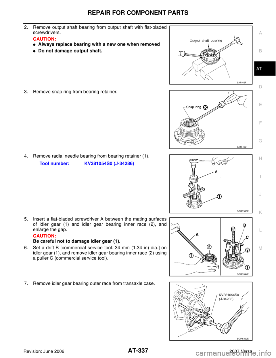
2. Remove output shaft bearing from output shaft with flat-bladed
screwdrivers.
CAUTION:
�Always replace bearing with a new one when removed
�Do not damage output shaft.
3. Remove snap ring from bearing retainer.
4. Remove radial needle bearing from bearing retainer (1).
5. Insert a flat-bladed screwdriver A between the mating surfaces
of idler gear (1) and idler gear bearing inner race (2), and
enlarge the gap.
CAUTION:
Be careful not to damage idler gear (1).
6. Set a drift B [commercial service tool: 34 mm (1.34 in) dia.] on
idler gear (1), and remove idler gear bearing inner race (2) using
a puller C (commercial service tool).
7. Remove idler gear bearing outer race from transaxle case.
SAT1 6 5F
SAT6 4 6D
Tool number: KV381054S0 (J-34286)
SCIA7993E
SCIA7044E
SCIA5390E
Page 354 of 2896
REPAIR FOR COMPONENT PARTS
AT-341
D
E
F
G
H
I
J
K
L
MA
B
AT
Revision: June 20062007 Versa
5. Press output shaft bearing on output shaft.
CAUTION:
�Do not reuse output shaft bearing.
�Apply ATF to output shaft bearing.
6. Set drift [commercial service tool] on radial needle bearing, and
press radial needle bearing into bearing retainer.
7. Install snap ring to bearing retainer.
8. After packing ring grooves with petroleum jelly, carefully install
new seal rings (1) on output shaft (2) and bearing retainer (3).
SAT8 6 3D
SAT6 5 8D
SAT6 5 9D
SCIA7996E
Page 356 of 2896

REPAIR FOR COMPONENT PARTS
AT-343
D
E
F
G
H
I
J
K
L
MA
B
AT
Revision: June 20062007 Versa
Band Servo Piston AssemblyUCS005WE
COMPONENTS
DISASSEMBLY
1. Push in OD servo piston assembly using a puller A (commercial
service tool) and a suitable drift B, and then remove snap ring
(1) from transaxle case using a flat-bladed screwdriver C.
2. Apply compressed air into the oil hole as shown in the figure to
remove OD servo piston assembly and band servo piston
assembly.
CAUTION:
Do not blow air in too quickly, or OD servo piston assembly,
band servo piston assembly and ATF could jump out. Care-
fully blow air little by little while protecting with lint-free
cloth A.
3. Remove 2nd servo return spring from transaxle case.
1. Lock nut 2. Anchor end pin 3. O-ring
4. Servo piston retainer 5. D-ring 6. OD servo piston
7. O-ring 8. Snap ring 9. OD servo piston retainer
10. E-ring 11. Spring retainer 12. OD servo return spring
13. D-ring 14. Band servo piston 15. Band servo thrust washer
16. Band servo piston stem 17. 2nd servo return spring
Refer to GI section to make sure icons (symbol marks) in the figure. Refer to GI-10, "
Components" .
SCIA7965E
SCIA7050E
SCIA7051E
Page 361 of 2896
AT-348
REPAIR FOR COMPONENT PARTS
Revision: June 20062007 Versa
10. Install OD servo piston assembly (2) to transaxle case (1).
11. Push in OD servo piston assembly using a puller A (commercial
service tool) and a suitable drift B, and install snap ring (1) to
transaxle case using a flat-bladed screwdriver C.
SCIA6010J
SCIA7050E
Page 365 of 2896

AT-352
REPAIR FOR COMPONENT PARTS
Revision: June 20062007 Versa
c. Adjust the back clearance of side gear according to the following
procedures.
i. Insert feeler gauges A of the same thickness to the back of side
gear from both sides, preventing side gear from falling, to mea-
sure the clearance.
�Measure clearance 3 times by rotating side gears and take
the average.
CAUTION:
In all 3 measurements, maximize the clearance by aligning
teeth on side gears at the top and bottom at the same posi-
tion.
ii. Select side gear thrust washer so that the clearance will fall
within the standard.
iii. Turn differential case upside down, and measure the back clear-
ance of the other side gear in the same manner.
NOTE:
Adjust the clearance to approx. 0.1 mm (0.004 in) for used differ-
ential [driven approx. 3,000 km (1864 mile) or more].
4. Install lock pin (1) to pinion mate shaft using the pin punch A.
CAUTION:
�Do not reuse lock pin.
�Make sure that lock pin is flush with differential case.
5. Install speedometer drive gear on differential case.
6. Set drift A [commercial service tool] on differential side bearing
inner race, and press differential side bearing inner race into dif-
ferential case.
CAUTION:
Apply ATF to differential side bearings.
7. Install differential side bearing outer race and differential side
bearing adjusting shim on transaxle case. Refer to AT-354,
"Assembly (1)" . Differential side gear clearance:
Refer to AT-382, "
Final Drive" .
SCIA7061E
Tool number: KV32101000 (J-25689-A)
SCIA7228E
SAT3 1 3D
SCIA8005E


 to transaxle case (1).
11. Push in OD servo piston assembly using a puller A (commercial
servic")