Page 2820 of 2896
 “AIR BAG” and “SEAT
BELT PRE-TENSIONER”
EES002ES
The Supplemental Restr")
WT-2
PRECAUTIONS
Revision: June 20062007 Versa
PRECAUTIONSPFP:00001
Precautions for Supplemental Restraint System (SRS) “AIR BAG” and “SEAT
BELT PRE-TENSIONER”
EES002ES
The Supplemental Restraint System such as “AIR BAG” and “SEAT BELT PRE-TENSIONER”, used along
with a front seat belt, helps to reduce the risk or severity of injury to the driver and front passenger for certain
types of collision. This system includes seat belt switch inputs and dual stage front air bag modules. The SRS
system uses the seat belt switches to determine the front air bag deployment, and may only deploy one front
air bag, depending on the severity of a collision and whether the front occupants are belted or unbelted.
Information necessary to service the system safely is included in the SRS and SB section of this Service Man-
ual.
WAR NIN G:
�To avoid rendering the SRS inoperative, which could increase the risk of personal injury or death
in the event of a collision which would result in air bag inflation, all maintenance must be per-
formed by an authorized NISSAN/INFINITI dealer.
�Improper maintenance, including incorrect removal and installation of the SRS, can lead to per-
sonal injury caused by unintentional activation of the system. For removal of Spiral Cable and Air
Bag Module, see the SRS section.
�Do not use electrical test equipment on any circuit related to the SRS unless instructed to in this
Service Manual. SRS wiring harnesses can be identified by yellow and/or orange harnesses or
harness connectors.
Page 2821 of 2896
PREPARATION
WT-3
C
D
F
G
H
I
J
K
L
MA
B
WT
Revision: June 20062007 Versa
PREPARATIONPFP:00002
Special Service ToolEES002ET
The actual shapes of Kent-Moore tools may differ from those of special service tools illustrated here.
Commercial Service ToolsEES002EF
Tool number
(Kent-Moore No.)
Tool nameDescription
KV991B1000
(J-45295)
Transmitter activation tool
�Transmitter wake up operation
�ID registration procedure
W EIA0144E
Tool nameDescription
Power toolRemoving wheel nuts
PBIC0190E
Page 2824 of 2896
WT-6
ROAD WHEEL TIRE ASSEMBLY
Revision: June 20062007 Versa
ROAD WHEEL TIRE ASSEMBLYPFP:40300
Balancing WheelsEES002D8
Adjust wheel balance using road wheel center.
CAUTION:
�Be careful not to scratch the road wheel during removal.
�Use clip-on type wheel balance weights only.
Wheel balance (Maximum allowable unbalance):
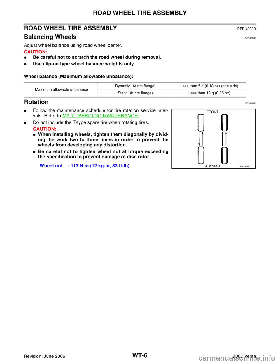
RotationEES002D9
�Follow the maintenance schedule for tire rotation service inter-
vals. Refer to MA-7, "
PERIODIC MAINTENANCE" .
�Do not include the T-type spare tire when rotating tires.
CAUTION:
�When installing wheels, tighten them diagonally by divid-
ing the work two to three times in order to prevent the
wheels from developing any distortion.
�Be careful not to tighten wheel nut at torque exceeding
the specification to prevent damage of disc rotor.
Maximum allowable unbalanceDynamic (At rim flange) Less than 5 g (0.18 oz) (one side)
Static (At rim flange) Less than 10 g (0.35 oz)
Wheel nut : 113 N·m (12 kg-m, 83 ft-lb)SM A82 9C
Page 2847 of 2896
SERVICE DATA AND SPECIFICATIONS (SDS)
WT-29
C
D
F
G
H
I
J
K
L
MA
B
WT
Revision: June 20062007 Versa
SERVICE DATA AND SPECIFICATIONS (SDS)PFP:00030
Road WheelEES002DA
TireEES002DB
Unit: kPa (kg/cm2 , psi)
*: D or R depending on manufacturer.Standard itemAllowable
Aluminum Steel
Maximum radial runout limitLateral deflection Less than 0.3 mm
(0.012 in)Less than 0.5 mm
(0.020 in)
Radial deflection Less than 0.3 mm
(0.012 in)Less than 0.8 mm
(0.031 in)
Maximum allowable unbalanceDynamic
(At rim flange)Less than 5 g (0.18 oz) (one side)
Static (At rim flange) Less than 10 g (0.35 oz)
Tire size/speed
ratingAir pressure
Conventional tire
Spare tire
Front wheel Rear wheel
P185/65R15 86H 230 (2.3, 33) 230 (2.3, 33) —
T125/70*15 — — 420 (4.2, 60)
Page 2848 of 2896
WT-30
SERVICE DATA AND SPECIFICATIONS (SDS)
Revision: June 20062007 Versa
Page 2851 of 2896
 “AIR BAG” and “SEAT
BELT PRE-TENSIONER”
EKS00IC")
PRECAUTION
WW-3
C
D
E
F
G
H
I
J
L
MA
B
WW
Revision: June 20062007 Versa
PRECAUTIONPFP:00011
Precautions for Supplemental Restraint System (SRS) “AIR BAG” and “SEAT
BELT PRE-TENSIONER”
EKS00ICZ
The Supplemental Restraint System such as “AIR BAG” and “SEAT BELT PRE-TENSIONER”, used along
with a front seat belt, helps to reduce the risk or severity of injury to the driver and front passenger for certain
types of collision. This system includes seat belt switch inputs and dual stage front air bag modules. The SRS
system uses the seat belt switches to determine the front air bag deployment, and may only deploy one front
air bag, depending on the severity of a collision and whether the front occupants are belted or unbelted.
Information necessary to service the system safely is included in the SRS and SB section of this Service Man-
ual.
WA RN ING:
�To avoid rendering the SRS inoperative, which could increase the risk of personal injury or death
in the event of a collision which would result in air bag inflation, all maintenance must be per-
formed by an authorized NISSAN/INFINITI dealer.
�Improper maintenance, including incorrect removal and installation of the SRS, can lead to per-
sonal injury caused by unintentional activation of the system. For removal of Spiral Cable and Air
Bag Module, see the SRS section.
�Do not use electrical test equipment on any circuit related to the SRS unless instructed to in this
Service Manual. SRS wiring harnesses can be identified by yellow and/or orange harnesses or
harness connectors.
Precautions for Procedures without Cowl Top CoverEKS00I1E
When performing the procedure after removing cowl top cover, cover
the lower end of windshield with urethane, etc.
PIIB3706J


WT-29
C
D
F
G
H
I
J
K
L
MA
B
WT
Revision: June 20062007 Versa
SERVICE DATA AND SPECIFICATIONS (SDS)PFP:00030
Road WheelEES002DA
TireEES002DB
Unit: kPa (kg/cm2 ,")

Revision: June 20062007 Versa")