Page 1465 of 2896
EC-296Revision: June 2006
DTC P0181 FTT SENSOR
2007 Versa
Removal and InstallationUBS00QGJ
FUEL TANK TEMPERATURE SENSOR
Refer to FL-5, "FUEL LEVEL SENSOR UNIT, FUEL FILTER AND FUEL PUMP ASSEMBLY" .
Page 1470 of 2896
DTC P0182, P0183 FTT SENSOR
EC-301
C
D
E
F
G
H
I
J
K
L
MA
EC
Revision: June 20062007 Versa
Removal and InstallationUBS00QGQ
FUEL TANK TEMPERATURE SENSOR
Refer to FL-5, "FUEL LEVEL SENSOR UNIT, FUEL FILTER AND FUEL PUMP ASSEMBLY" .
Page 1570 of 2896
DTC P0455 EVAP CONTROL SYSTEM
EC-401
C
D
E
F
G
H
I
J
K
L
MA
EC
Revision: June 20062007 Versa
5. CHECK EVAP PURGE LINE
Check EVAP purge line (pipe, rubber tube, fuel tank and EVAP canister) for cracks, improper connection or
disconnection.
Refer to EC-31, "
EVAPORATIVE EMISSION SYSTEM" .
OK or NG
OK >> GO TO 6.
NG >> Repair or reconnect the hose.
6. CLEAN EVAP PURGE LINE
Clean EVAP purge line (pipe and rubber tube) using air blower.
>> GO TO 7.
7. CHECK EVAP CANISTER VENT CONTROL VALVE
Check the following.
�EVAP canister vent control is installed properly.
Refer to EC-35, "
Removal and Installation" .
�EVAP canister vent control valve.
Refer to EC-374, "
Component Inspection" .
OK or NG
OK >> GO TO 8.
NG >> Repair or replace EVAP canister vent control valve and O-ring.
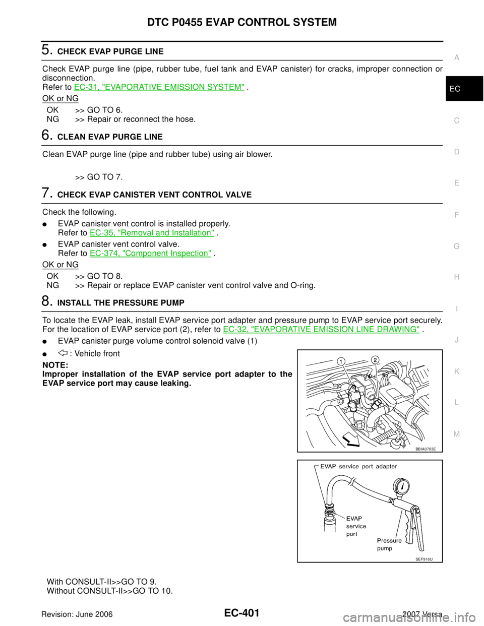
8. INSTALL THE PRESSURE PUMP
To locate the EVAP leak, install EVAP service port adapter and pressure pump to EVAP service port securely.
For the location of EVAP service port (2), refer to EC-32, "
EVAPORATIVE EMISSION LINE DRAWING" .
�EVAP canister purge volume control solenoid valve (1)
� : Vehicle front
NOTE:
Improper installation of the EVAP service port adapter to the
EVAP service port may cause leaking.
With CONSULT-II>>GO TO 9.
Without CONSULT-II>>GO TO 10.
BBIA0703E
SEF 9 16 U
Page 1587 of 2896
EC-418Revision: June 2006
DTC P0461 FUEL LEVEL SENSOR
2007 Versa
5. Turn ignition switch OFF and wait at least 10 seconds then turn
ON.
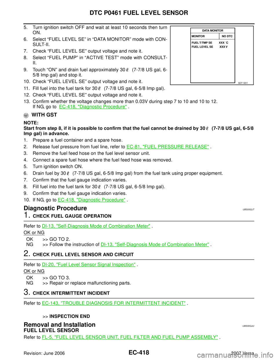
6. Select “FUEL LEVEL SE” in “DATA MONITOR” mode with CON-
SULT-II.
7. Check “FUEL LEVEL SE” output voltage and note it.
8. Select “FUEL PUMP” in “ACTIVE TEST” mode with CONSULT-
II.
9. Touch “ON” and drain fuel approximately 30 (7-7/8 US gal, 6-
5/8 Imp gal) and stop it.
10. Check “FUEL LEVEL SE” output voltage and note it.
11. Fill fuel into the fuel tank for 30 (7-7/8 US gal, 6-5/8 Imp gal).
12. Check “FUEL LEVEL SE” output voltage and note it.
13. Confirm whether the voltage changes more than 0.03V during step 7 to 10 and 10 to 12.
If NG, go to EC-418, "
Diagnostic Procedure" .
WITH GST
NOTE:
Start from step 8, if it is possible to confirm that the fuel cannot be drained by 30 (7-7/8 US gal, 6-5/8
Imp gal) in advance.
1. Prepare a fuel container and a spare hose.
2. Release fuel pressure from fuel line, refer to EC-81, "
FUEL PRESSURE RELEASE" .
3. Remove the fuel feed hose on the fuel level sensor unit.
4. Connect a spare fuel hose where the fuel feed hose was removed.
5. Turn ignition switch ON.
6. Drain fuel by 30 (7-7/8 US gal, 6-5/8 Imp gal) from the fuel tank using proper equipment.
7. Confirm that the fuel gauge indication varies.
8. Fill fuel into the fuel tank for 30 (7-7/8 US gal, 6-5/8 Imp gal).
9. Confirm that the fuel gauge indication varies.
10. If NG, go to EC-418, "
Diagnostic Procedure" .
Diagnostic ProcedureUBS00QJT
1. CHECK FUEL GAUGE OPERATION
Refer to DI-13, "
Self-Diagnosis Mode of Combination Meter" .
OK or NG
OK >> GO TO 2.
NG >> Follow the instruction of DI-13, "
Self-Diagnosis Mode of Combination Meter" .
2. CHECK FUEL LEVEL SENSOR AND CIRCUIT
Refer to DI-20, "
Fuel Level Sensor Signal Inspection" .
OK or NG
OK >> GO TO 3.
NG >> Repair or replace malfunctioning parts.
3. CHECK INTERMITTENT INCIDENT
Refer to EC-143, "
TROUBLE DIAGNOSIS FOR INTERMITTENT INCIDENT" .
>>INSPECTION END
Removal and InstallationUBS00QJU
FUEL LEVEL SENSOR
Refer to FL-5, "FUEL LEVEL SENSOR UNIT, FUEL FILTER AND FUEL PUMP ASSEMBLY" .
SEF 1 95 Y
Page 1958 of 2896
FL-1
FUEL SYSTEM
B ENGINE
CONTENTS
C
D
E
F
G
H
I
J
K
L
M
SECTION FL
A
FL
Revision: June 20062007 Versa PRECAUTIONS .......................................................... 2
Precautions for Supplemental Restraint System
(SRS) “AIR BAG” and “SEAT BELT PRE-TEN-
SIONER” .................................................................. 2
PREPARATION ........................................................... 3
Special Service Tools ............................................... 3
Commercial Service Tools ........................................ 3
FUEL SYSTEM ........................................................... 4
Checking Fuel Lines ................................................. 4
General Precautions ................................................ 4
FUEL LEVEL SENSOR UNIT, FUEL FILTER AND
FUEL PUMP ASSEMBLY ........................................... 5Components ............................................................. 5
Removal and Installation .......................................... 5
REMOVAL ............................................................. 5
INSPECTION AFTER REMOVAL ......................... 7
INSTALLATION ..................................................... 7
INSPECTION AFTER INSTALLATION .................. 8
FUEL TANK ................................................................ 9
Components ............................................................. 9
Removal and Installation .......................................... 9
REMOVAL ............................................................. 9
INSTALLATION ................................................... 12
INSPECTION AFTER INSTALLATION ................ 12
SERVICE DATA AND SPECIFICATIONS (SDS) ...... 13
Standard and Limit .................................................. 13
FUEL TANK ......................................................... 13
Page 1962 of 2896
FUEL LEVEL SENSOR UNIT, FUEL FILTER AND FUEL PUMP ASSEMBLY
FL-5
C
D
E
F
G
H
I
J
K
L
MA
FL
Revision: June 20062007 Versa
FUEL LEVEL SENSOR UNIT, FUEL FILTER AND FUEL PUMP ASSEMBLYPFP:17042
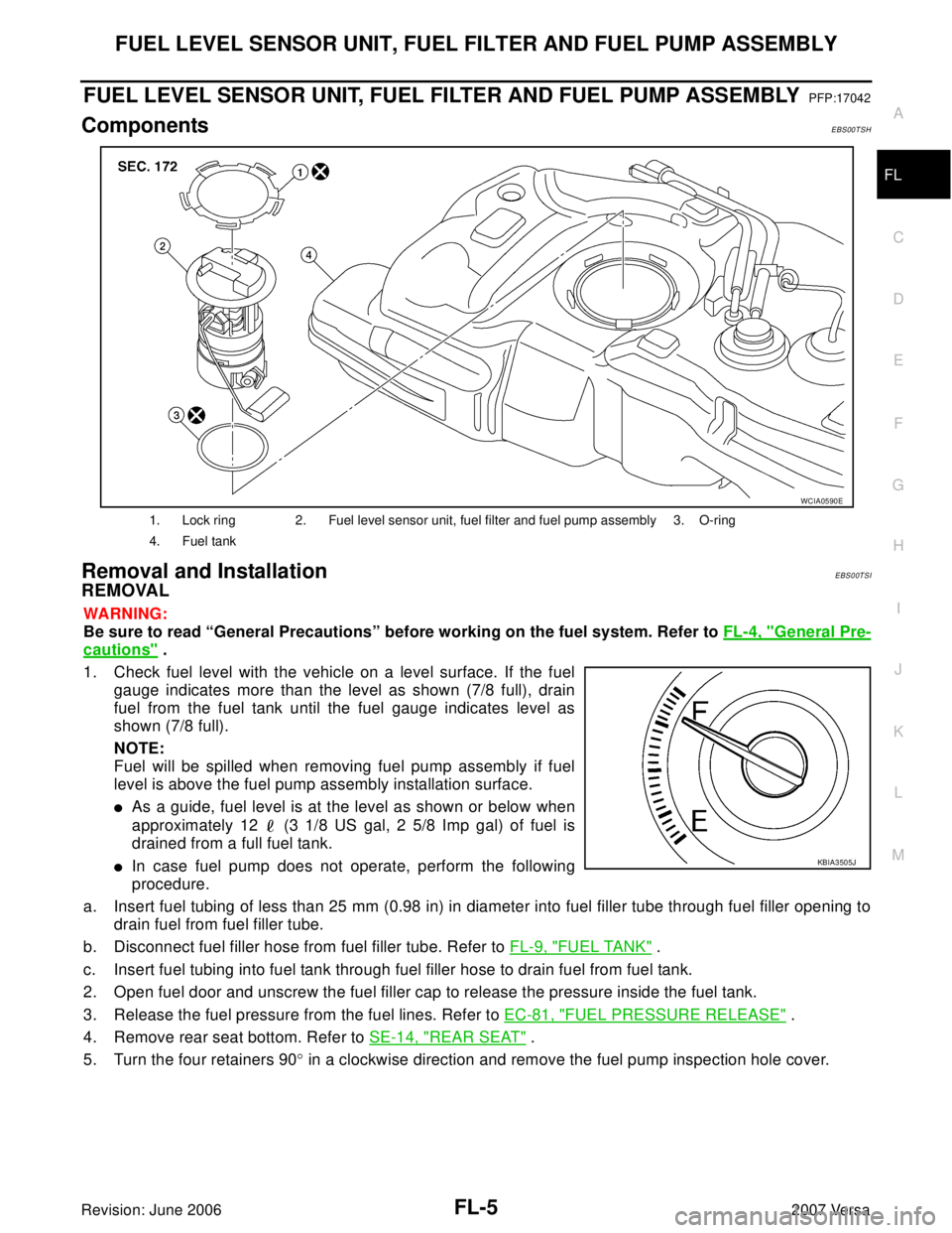
ComponentsEBS00TSH
Removal and InstallationEBS00TSI
REMOVAL
WA RN ING:
Be sure to read “General Precautions” before working on the fuel system. Refer to FL-4, "
General Pre-
cautions" .
1. Check fuel level with the vehicle on a level surface. If the fuel
gauge indicates more than the level as shown (7/8 full), drain
fuel from the fuel tank until the fuel gauge indicates level as
shown (7/8 full).
NOTE:
Fuel will be spilled when removing fuel pump assembly if fuel
level is above the fuel pump assembly installation surface.
�As a guide, fuel level is at the level as shown or below when
approximately 12 (3 1/8 US gal, 2 5/8 Imp gal) of fuel is
drained from a full fuel tank.
�In case fuel pump does not operate, perform the following
procedure.
a. Insert fuel tubing of less than 25 mm (0.98 in) in diameter into fuel filler tube through fuel filler opening to
drain fuel from fuel filler tube.
b. Disconnect fuel filler hose from fuel filler tube. Refer to FL-9, "
FUEL TANK" .
c. Insert fuel tubing into fuel tank through fuel filler hose to drain fuel from fuel tank.
2. Open fuel door and unscrew the fuel filler cap to release the pressure inside the fuel tank.
3. Release the fuel pressure from the fuel lines. Refer to EC-81, "
FUEL PRESSURE RELEASE" .
4. Remove rear seat bottom. Refer to SE-14, "
REAR SEAT" .
5. Turn the four retainers 90° in a clockwise direction and remove the fuel pump inspection hole cover.
1. Lock ring 2. Fuel level sensor unit, fuel filter and fuel pump assembly 3. O-ring
4. Fuel tank
WCIA0590E
KBIA3505J
Page 1964 of 2896
FUEL LEVEL SENSOR UNIT, FUEL FILTER AND FUEL PUMP ASSEMBLY
FL-7
C
D
E
F
G
H
I
J
K
L
MA
FL
Revision: June 20062007 Versa
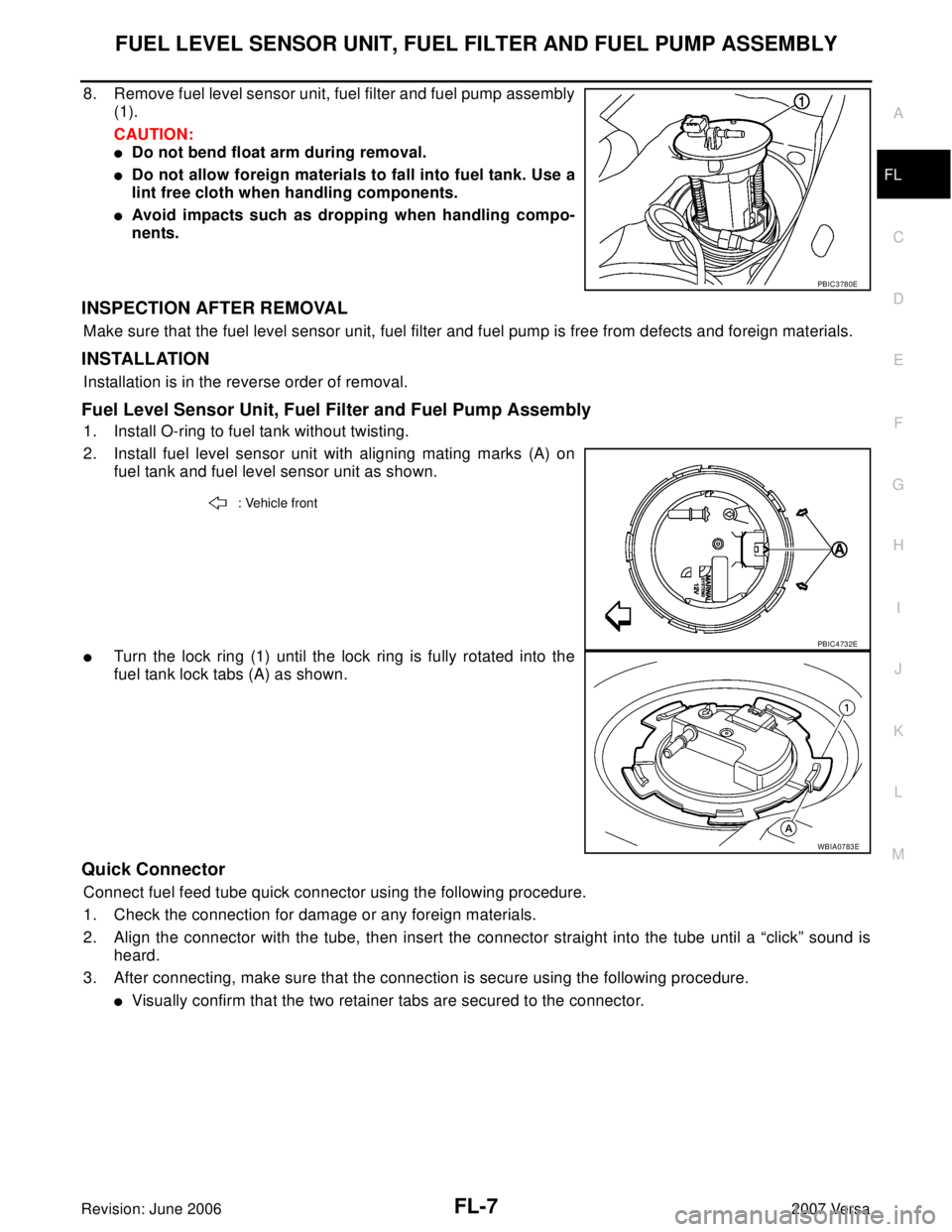
8. Remove fuel level sensor unit, fuel filter and fuel pump assembly
(1).
CAUTION:
�Do not bend float arm during removal.
�Do not allow foreign materials to fall into fuel tank. Use a
lint free cloth when handling components.
�Avoid impacts such as dropping when handling compo-
nents.
INSPECTION AFTER REMOVAL
Make sure that the fuel level sensor unit, fuel filter and fuel pump is free from defects and foreign materials.
INSTALLATION
Installation is in the reverse order of removal.
Fuel Level Sensor Unit, Fuel Filter and Fuel Pump Assembly
1. Install O-ring to fuel tank without twisting.
2. Install fuel level sensor unit with aligning mating marks (A) on
fuel tank and fuel level sensor unit as shown.
�Turn the lock ring (1) until the lock ring is fully rotated into the
fuel tank lock tabs (A) as shown.
Quick Connector
Connect fuel feed tube quick connector using the following procedure.
1. Check the connection for damage or any foreign materials.
2. Align the connector with the tube, then insert the connector straight into the tube until a “click” sound is
heard.
3. After connecting, make sure that the connection is secure using the following procedure.
�Visually confirm that the two retainer tabs are secured to the connector.
PBIC3780E
: Vehicle front
PBIC4732E
WBIA0783E
Page 1966 of 2896
FUEL TANK
FL-9
C
D
E
F
G
H
I
J
K
L
MA
FL
Revision: June 20062007 Versa
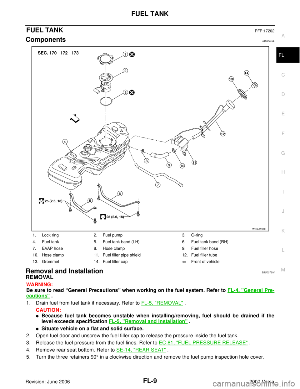
FUEL TANKPFP:17202
ComponentsEBS00TSL
Removal and InstallationEBS00TSM
REMOVAL
WA RN ING:
Be sure to read “General Precautions” when working on the fuel system. Refer to FL-4, "
General Pre-
cautions" .
1. Drain fuel from fuel tank if necessary. Refer to FL-5, "
REMOVAL" .
CAUTION:
�Because fuel tank becomes unstable when installing/removing, fuel should be drained if the
level exceeds specification FL-5, "
Removal and Installation" .
�Situate vehicle on a flat and solid surface.
2. Open fuel door and unscrew the fuel filler cap to release the pressure inside the fuel tank.
3. Release the fuel pressure from the fuel lines. Refer to EC-81, "
FUEL PRESSURE RELEASE" .
4. Remove rear seat bottom. Refer to SE-14, "
REAR SEAT" .
5. Turn the three retainers 90° in a clockwise direction and remove the fuel pump inspection hole cover.
1. Lock ring 2. Fuel pump 3. O-ring
4. Fuel tank 5. Fuel tank band (LH) 6. Fuel tank band (RH)
7. EVAP hose 8. Hose clamp 9. Fuel filler hose
10. Hose clamp 11. Fuel filler pipe shield 12. Fuel filler tube
13. Grommet 14. Fuel filler cap⇐Front of vehicle
WCIA0591E