Page 1721 of 2896
EC-552Revision: June 2006
ASCD BRAKE SWITCH
2007 Versa
Diagnostic ProcedureUBS00QNZ
1. CHECK OVERALL FUNCTION-I
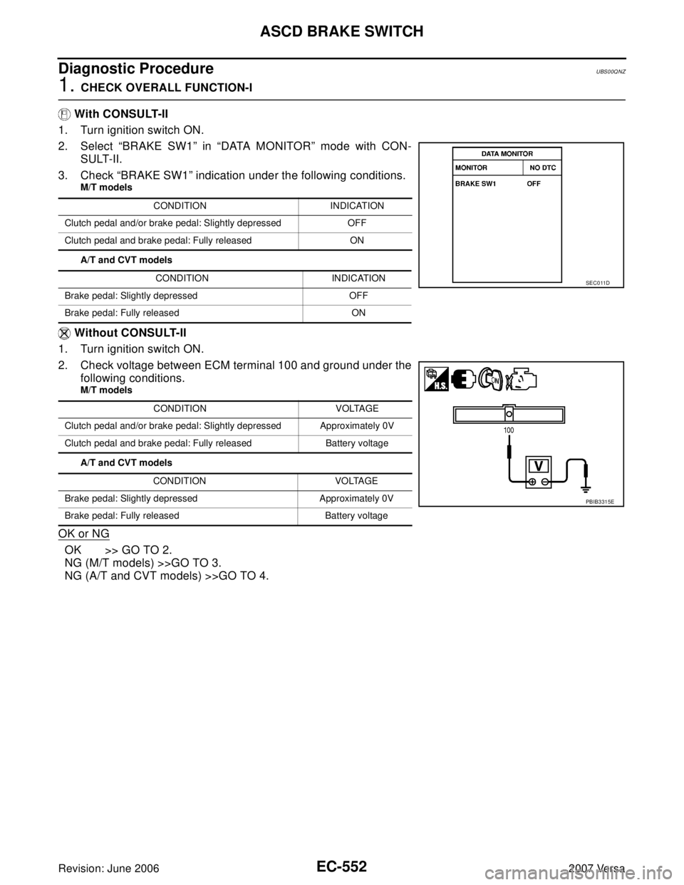
With CONSULT-II
1. Turn ignition switch ON.
2. Select “BRAKE SW1” in “DATA MONITOR” mode with CON-
SULT-II.
3. Check “BRAKE SW1” indication under the following conditions.
M/T models
A/T and CVT models
Without CONSULT-II
1. Turn ignition switch ON.
2. Check voltage between ECM terminal 100 and ground under the
following conditions.
M/T models
A/T and CVT models
OK or NG
OK >> GO TO 2.
NG (M/T models) >>GO TO 3.
NG (A/T and CVT models) >>GO TO 4.
CONDITION INDICATION
Clutch pedal and/or brake pedal: Slightly depressed OFF
Clutch pedal and brake pedal: Fully released ON
CONDITION INDICATION
Brake pedal: Slightly depressed OFF
Brake pedal: Fully released ON
CONDITION VOLTAGE
Clutch pedal and/or brake pedal: Slightly depressed Approximately 0V
Clutch pedal and brake pedal: Fully released Battery voltage
CONDITION VOLTAGE
Brake pedal: Slightly depressed Approximately 0V
Brake pedal: Fully released Battery voltage
SEC0 11D
PBIB3315E
Page 1722 of 2896
ASCD BRAKE SWITCH
EC-553
C
D
E
F
G
H
I
J
K
L
MA
EC
Revision: June 20062007 Versa
2. CHECK OVERALL FUNCTION-II
With CONSULT-II
Check “BRAKE SW2” indication in “DATA MONITOR” mode.
Without CONSULT-II
Check voltage between ECM terminal 99 and ground under the fol-
lowing conditions.
OK or NG
OK >> GO TO 15.
NG >> GO TO 11.
3. CHECK ASCD CLUTCH SWITCH POWER SUPPLY CIRCUIT
1. Turn ignition switch OFF.
2. Disconnect ASCD clutch switch (1) harness connector.
–Clutch pedal (2)
3. Turn ignition switch ON.
4. Check voltage between ASCD clutch switch terminal 1 and
ground with CONSULT-II or tester.
OK or NG
OK >> GO TO 9.
NG >> GO TO 4.
CONDITION INDICATION
Brake pedal: Fully released OFF
Brake pedal: Slightly depressed ON
SEC0 13 D
CONDITION VOLTAGE
Brake pedal: Fully released Approximately 0V
Brake pedal: Slightly depressed Battery voltage
PBIB0 311 E
BBIA0709E
Voltage: Battery voltage
PBIB0857E
Page 1723 of 2896
EC-554Revision: June 2006
ASCD BRAKE SWITCH
2007 Versa
4. CHECK ASCD BRAKE SWITCH POWER SUPPLY
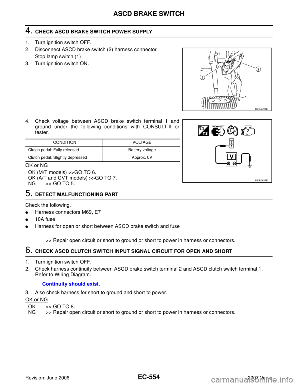
1. Turn ignition switch OFF.
2. Disconnect ASCD brake switch (2) harness connector.
–Stop lamp switch (1)
3. Turn ignition switch ON.
4. Check voltage between ASCD brake switch terminal 1 and
ground under the following conditions with CONSULT-II or
tester.
OK or NG
OK (M/T models) >>GO TO 6.
OK (A/T and CVT models) >>GO TO 7.
NG >> GO TO 5.
5. DETECT MALFUNCTIONING PART
Check the following.
�Harness connectors M69, E7
�10A fuse
�Harness for open or short between ASCD brake switch and fuse
>> Repair open circuit or short to ground or short to power in harness or connectors.
6. CHECK ASCD CLUTCH SWITCH INPUT SIGNAL CIRCUIT FOR OPEN AND SHORT
1. Turn ignition switch OFF.
2. Check harness continuity between ASCD brake switch terminal 2 and ASCD clutch switch terminal 1.
Refer to Wiring Diagram.
3. Also check harness for short to ground and short to power.
OK or NG
OK >> GO TO 8.
NG >> Repair open circuit or short to ground or short to power in harness or connectors.
BBIA0708E
CONDITION VOLTAGE
Clutch pedal: Fully released Battery voltage
Clutch pedal: Slightly depressed Approx. 0V
PBIB0857E
Continuity should exist.
Page 1724 of 2896
ASCD BRAKE SWITCH
EC-555
C
D
E
F
G
H
I
J
K
L
MA
EC
Revision: June 20062007 Versa
7. CHECK ASCD BRAKE SWITCH INPUT SIGNAL CIRCUIT FOR OPEN AND SHORT
1. Turn ignition switch OFF.
2. Disconnect ECM harness connector.
3. Check harness continuity between ECM terminal 100 and ASCD brake switch terminal 2.
Refer to Wiring Diagram.
4. Also check harness for short to ground and short to power.
OK or NG
OK >> GO TO 8.
NG >> Repair open circuit or short to ground or short to power in harness or connectors.
8. CHECK ASCD BRAKE SWITCH
Refer to EC-481, "
Component Inspection" .
OK or NG
OK >> GO TO 15.
NG >> Replace ASCD brake switch.
9. CHECK ASCD CLUTCH SWITCH INPUT SIGNAL CIRCUIT FOR OPEN AND SHORT
1. Turn ignition switch OFF.
2. Disconnect ECM harness connector.
3. Check harness continuity between ECM terminal 100 and ASCD clutch switch terminal 2.
Refer to Wiring Diagram.
4. Also check harness for short to ground and short to power.
OK or NG
OK >> GO TO 10.
NG >> Repair open circuit or short to ground or short to power in harness or connectors.
10. CHECK ASCD CLUTCH SWITCH
Refer to EC-481, "
Component Inspection"
OK or NG
OK >> GO TO 15.
NG >> Replace ASCD clutch switch.Continuity should exist.
Continuity should exist.
Page 1725 of 2896
EC-556Revision: June 2006
ASCD BRAKE SWITCH
2007 Versa
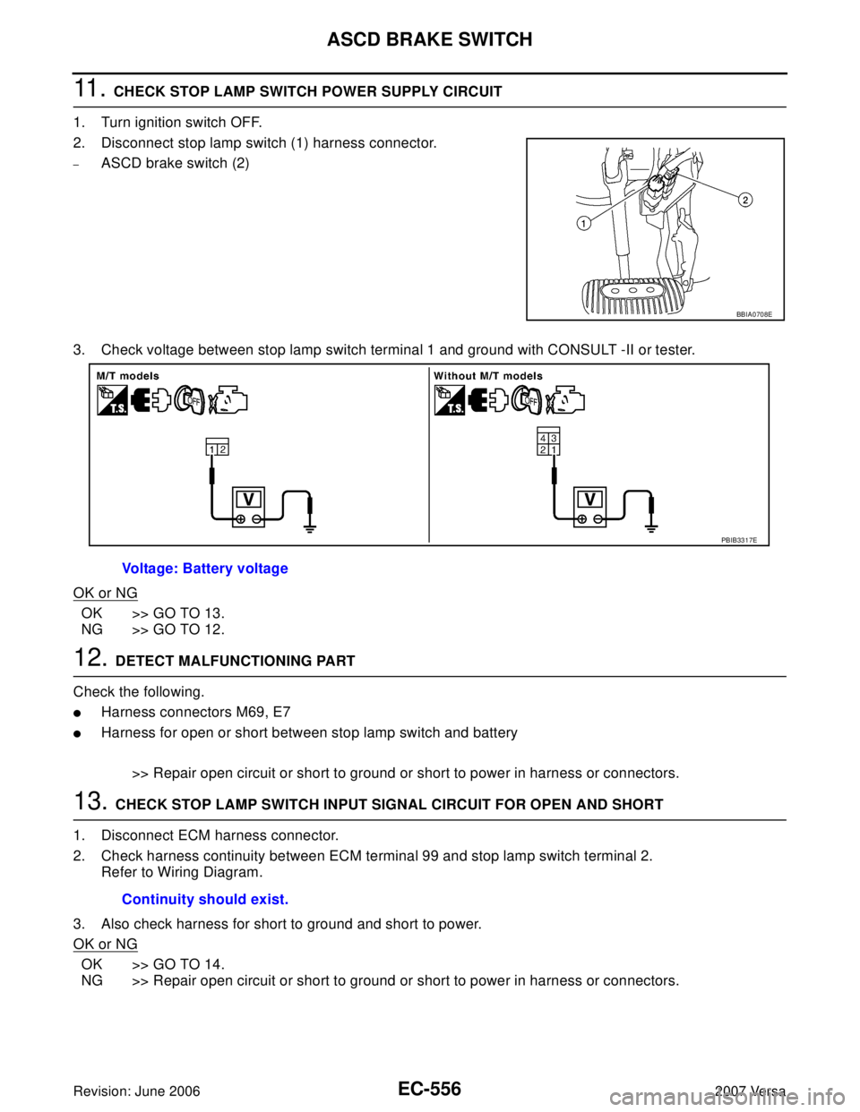
11 . CHECK STOP LAMP SWITCH POWER SUPPLY CIRCUIT
1. Turn ignition switch OFF.
2. Disconnect stop lamp switch (1) harness connector.
–ASCD brake switch (2)
3. Check voltage between stop lamp switch terminal 1 and ground with CONSULT -II or tester.
OK or NG
OK >> GO TO 13.
NG >> GO TO 12.
12. DETECT MALFUNCTIONING PART
Check the following.
�Harness connectors M69, E7
�Harness for open or short between stop lamp switch and battery
>> Repair open circuit or short to ground or short to power in harness or connectors.
13. CHECK STOP LAMP SWITCH INPUT SIGNAL CIRCUIT FOR OPEN AND SHORT
1. Disconnect ECM harness connector.
2. Check harness continuity between ECM terminal 99 and stop lamp switch terminal 2.
Refer to Wiring Diagram.
3. Also check harness for short to ground and short to power.
OK or NG
OK >> GO TO 14.
NG >> Repair open circuit or short to ground or short to power in harness or connectors.
BBIA0708E
Voltage: Battery voltage
PBIB3317E
Continuity should exist.
Page 1726 of 2896
ASCD BRAKE SWITCH
EC-557
C
D
E
F
G
H
I
J
K
L
MA
EC
Revision: June 20062007 Versa
14. CHECK STOP LAMP SWITCH
Refer to EC-481, "
Component Inspection"
OK or NG
OK >> GO TO 15.
NG >> Replace stop lamp switch.
15. CHECK INTERMITTENT INCIDENT
Refer to EC-143, "
TROUBLE DIAGNOSIS FOR INTERMITTENT INCIDENT" .
>>INSPECTION END
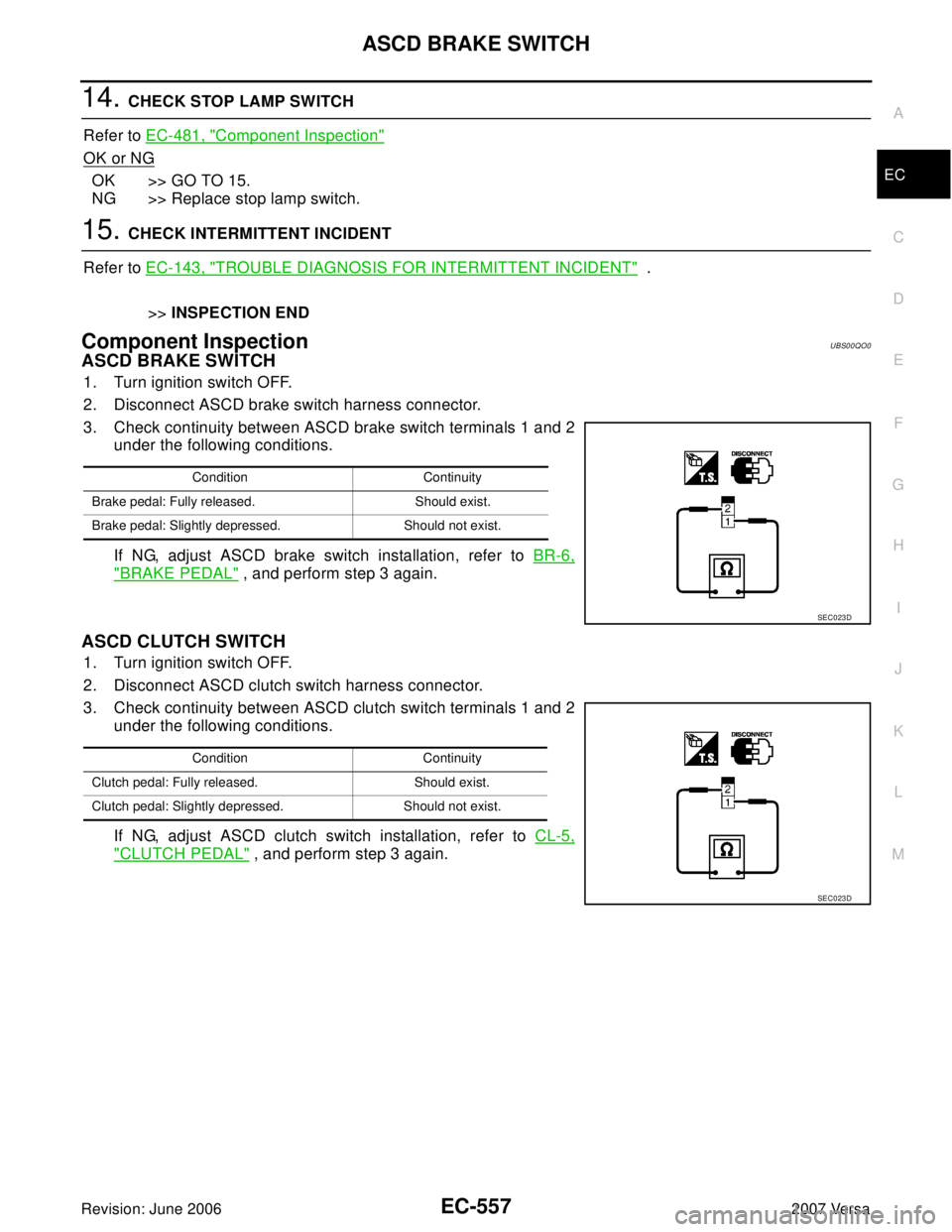
Component InspectionUBS00QO0
ASCD BRAKE SWITCH
1. Turn ignition switch OFF.
2. Disconnect ASCD brake switch harness connector.
3. Check continuity between ASCD brake switch terminals 1 and 2
under the following conditions.
If NG, adjust ASCD brake switch installation, refer to BR-6,
"BRAKE PEDAL" , and perform step 3 again.
ASCD CLUTCH SWITCH
1. Turn ignition switch OFF.
2. Disconnect ASCD clutch switch harness connector.
3. Check continuity between ASCD clutch switch terminals 1 and 2
under the following conditions.
If NG, adjust ASCD clutch switch installation, refer to CL-5,
"CLUTCH PEDAL" , and perform step 3 again.
Condition Continuity
Brake pedal: Fully released. Should exist.
Brake pedal: Slightly depressed. Should not exist.
SEC0 23 D
Condition Continuity
Clutch pedal: Fully released. Should exist.
Clutch pedal: Slightly depressed. Should not exist.
SEC0 23 D
Page 1727 of 2896
EC-558Revision: June 2006
ASCD BRAKE SWITCH
2007 Versa
STOP LAMP SWITCH
1. Turn ignition switch OFF.
2. Disconnect stop lamp switch harness connector.
3. Check continuity between stop lamp switch terminals 1 and 2 under the following conditions.
If NG, adjust stop lamp switch installation, refer to BR-6, "
BRAKE PEDAL" , and perform step 3 again.
Condition Continuity
Brake pedal: Fully released. Should not exist.
Brake pedal: Slightly depressed. Should exist.
PBIB3318E
Page 1863 of 2896
EM-54Revision: June 2006
CAMSHAFT
2007 Versa
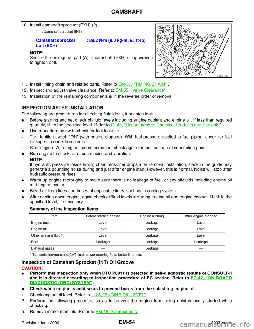
10. Install camshaft sprocket (EXH) (2).
NOTE:
Secure the hexagonal part (A) of camshaft (EXH) using wrench
to tighten bolt.
11. Install timing chain and related parts. Refer to EM-37, "
TIMING CHAIN" .
12. Inspect and adjust valve clearance. Refer to EM-55, "
Valve Clearance" .
13. Installation of the remaining components is in the reverse order of removal.
INSPECTION AFTER INSTALLATION
The following are procedures for checking fluids leak, lubricates leak.
�Before starting engine, check oil/fluid levels including engine coolant and engine oil. If less than required
quantity, fill to the specified level. Refer to GI-46, "
Recommended Chemical Products and Sealants" .
�Use procedure below to check for fuel leakage.
–Turn ignition switch “ON” (with engine stopped). With fuel pressure applied to fuel piping, check for fuel
leakage at connection points.
–Start engine. With engine speed increased, check again for fuel leakage at connection points.
�Run engine to check for unusual noise and vibration.
NOTE:
If hydraulic pressure inside timing chain tensioner drops after removal/installation, slack in the guide may
generate a pounding noise during and just after engine start. However, this is normal. Noise will stop after
hydraulic pressure rises.
�Warm up engine thoroughly to make sure there is no leakage of fuel, or any oil/fluids including engine oil
and engine coolant.
�Bleed air from lines and hoses of applicable lines, such as in cooling system.
�After cooling down engine, again check oil/fluid levels including engine oil and engine coolant. Refill to the
specified level, if necessary.
Summary of the inspection items:
* Transmission/transaxle/CVT fluid, power steering fluid, brake fluid, etc.
Inspection of Camshaft Sprocket (INT) Oil Groove
CAUTION:
�Perform this inspection only when DTC P0011 is detected in self-diagnostic results of CONSULT-II
and it is directed according to inspection procedure of EC section. Refer to EC-47, "
ON BOARD
DIAGNOSTIC (OBD) SYSTEM" .
�Check when engine is cold so as to prevent burns from the splashing engine oil.
1. Check engine oil level. Refer to LU-5, "
ENGINE OIL LEVEL" .
2. Perform the following procedure so as to prevent the engine from being unintentionally started while
checking.
a. Remove intake manifold. Refer to EM-18, "
Components" .
1 : Camshaft sprocket (INT)
Camshaft sprocket
bolt (EXH): 88.2 N·m (9.0 kg-m, 65 ft-lb)
PBIC3454J
Item Before starting engine Engine running After engine stopped
Engine coolant Level Leakage Level
Engine oil Level Leakage Level
Other oils and fluid* Level Leakage Level
Fuel Leakage Leakage Leakage
Exhaust gases — Leakage —