Page 1268 of 2896
TROUBLE DIAGNOSIS
EC-99
C
D
E
F
G
H
I
J
K
L
MA
EC
Revision: June 20062007 Versa
:Vehicle front
1. Crankshaft position sensor (POS) 2. Camshaft position sensor (PHASE) 3. EVAP canister purge volume con-
trol solenoid valve
4. EVAP service port 5. ECM harness connector 6. ECM
7. Stop lamp switch 8. Accelerator pedal position sensor
BBIA0727E
Page 1271 of 2896
EC-102Revision: June 2006
TROUBLE DIAGNOSIS
2007 Versa
Vacuum Hose DrawingUBS00PKJ
Refer to EC-22, "System Diagram" for Vacuum Control System.
: Vehicle front : From EVAP canister
1. Intake manifold 2. EVAP canister purge volume control
solenoid valve3. EVAP service port
4. EVAP purge resonator
NOTE:
Do not use soapy water or any type of solvent while installing vacuum hoses or purge hoses.
PBIB3330E
Page 1285 of 2896

EC-116Revision: June 2006
TROUBLE DIAGNOSIS
2007 Versa
*: This function is not necessary in the usual service procedure.
SELF-DIAG RESULTS MODE
Self Diagnostic Item
Regarding items of DTC and 1st trip DTC, refer to EC-48, "EMISSION-RELATED DIAGNOSTIC INFORMA-
TION ITEMS" .
Freeze Frame Data and 1st Trip Freeze Frame Data
EVAP SYSTEM CLOSE CLOSE THE EVAP CANISTER VENT CONTROL VALVE IN
ORDER TO MAKE EVAP SYSTEM CLOSE UNDER THE
FOLLOWING CONDITIONS.
�IGN SW “ON”
�ENGINE NOT RUNNING
�AMBIENT TEMPERATURE IS ABOVE 0°C (32°F).
�NO VACUUM AND NO HIGH PRESSURE IN EVAP SYS-
TEM
� FUEL TANK TEMP. IS MORE THAN 0°C (32°F).
�WITHIN 10 MINUTES AFTER STARTING “EVAP SYS-
TEM CLOSE”
�WHEN TRYING TO EXECUTE “EVAP SYSTEM CLOSE”
UNDER THE CONDITION EXCEPT ABOVE, CONSULT-
II WILL DISCONTINUE IT AND DISPLAY APPROPRI-
ATE INSTRUCTION.
NOTE:
WHEN STARTING ENGINE, CONSULT-II MAY DISPLAY
“BATTERY VOLTAGE IS LOW. CHARGE BATTERY”,
EVEN IN USING CHARGED BATTERY.When detecting EVAP vapor leak
point of EVAP system
TARGET IDLE RPM ADJ*
�IDLE CONDITION When setting target idle speed
TARGET IGN TIM ADJ*
�IDLE CONDITION When adjusting target ignition tim-
ing
VIN REGISTRATION
�IN THIS MODE, VIN IS REGISTERED IN ECM. When registering VIN in ECM WORK ITEM CONDITION USAGE
Freeze frame data
item*Description
DIAG TROUBLE
CODE
[PXXXX]
�The engine control component part/control system has a trouble code, it is displayed as PXXXX.
(Refer to EC-8, "
INDEX FOR DTC" .)
FUEL SYS-B1
�“Fuel injection system status” at the moment a malfunction is detected is displayed.
�One mode in the following is displayed.
Mode2: Open loop due to detected system malfunction
Mode3: Open loop due to driving conditions (power enrichment, deceleration enleanment)
Mode4: Closed loop - using oxygen sensor(s) as feedback for fuel control
Mode5: Open loop - has not yet satisfied condition to go to closed loop
CAL/LD VALUE [%]
�The calculated load value at the moment a malfunction is detected is displayed.
COOLANT TEMP
[°C] or [°F]
�The engine coolant temperature at the moment a malfunction is detected is displayed.
L-FUEL TRM-B1 [%]
�“Long-term fuel trim” at the moment a malfunction is detected is displayed.
�The long-term fuel trim indicates much more gradual feedback compensation to the base fuel schedule
than short-term fuel trim.
S-FUEL TRM-B1 [%]
�“Short-term fuel trim” at the moment a malfunction is detected is displayed.
�The short-term fuel trim indicates dynamic or instantaneous feedback compensation to the base fuel
schedule.
ENGINE SPEED
[rpm]
�The engine speed at the moment a malfunction is detected is displayed.
VEHICL SPEED
[km/h] or [mph]
�The vehicle speed at the moment a malfunction is detected is displayed.
Page 1295 of 2896

EC-126Revision: June 2006
TROUBLE DIAGNOSIS
2007 Versa
Generic Scan Tool (GST) FunctionUBS00PKO
DESCRIPTION
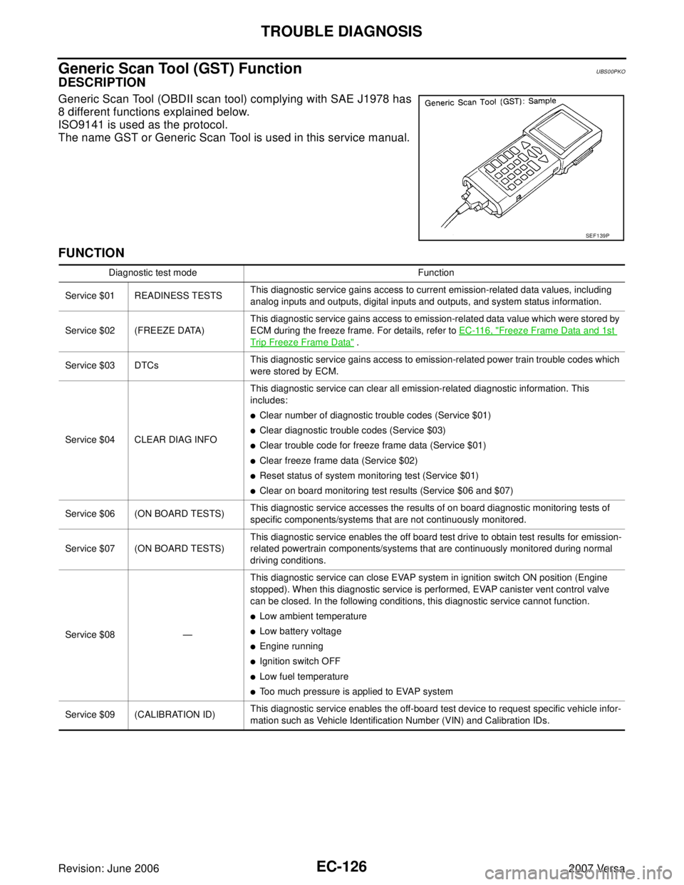
Generic Scan Tool (OBDII scan tool) complying with SAE J1978 has
8 different functions explained below.
ISO9141 is used as the protocol.
The name GST or Generic Scan Tool is used in this service manual.
FUNCTION
SEF 1 39 P
Diagnostic test mode Function
Service $01 READINESS TESTSThis diagnostic service gains access to current emission-related data values, including
analog inputs and outputs, digital inputs and outputs, and system status information.
Service $02 (FREEZE DATA)This diagnostic service gains access to emission-related data value which were stored by
ECM during the freeze frame. For details, refer to EC-116, "
Freeze Frame Data and 1st
Trip Freeze Frame Data" .
Service $03 DTCsThis diagnostic service gains access to emission-related power train trouble codes which
were stored by ECM.
Service $04 CLEAR DIAG INFO This diagnostic service can clear all emission-related diagnostic information. This
includes:
�Clear number of diagnostic trouble codes (Service $01)
�Clear diagnostic trouble codes (Service $03)
�Clear trouble code for freeze frame data (Service $01)
�Clear freeze frame data (Service $02)
�Reset status of system monitoring test (Service $01)
�Clear on board monitoring test results (Service $06 and $07)
Service $06 (ON BOARD TESTS)This diagnostic service accesses the results of on board diagnostic monitoring tests of
specific components/systems that are not continuously monitored.
Service $07 (ON BOARD TESTS)This diagnostic service enables the off board test drive to obtain test results for emission-
related powertrain components/systems that are continuously monitored during normal
driving conditions.
Service $08 —This diagnostic service can close EVAP system in ignition switch ON position (Engine
stopped). When this diagnostic service is performed, EVAP canister vent control valve
can be closed. In the following conditions, this diagnostic service cannot function.
�Low ambient temperature
�Low battery voltage
�Engine running
�Ignition switch OFF
�Low fuel temperature
�Too much pressure is applied to EVAP system
Service $09 (CALIBRATION ID)This diagnostic service enables the off-board test device to request specific vehicle infor-
mation such as Vehicle Identification Number (VIN) and Calibration IDs.
Page 1296 of 2896
TROUBLE DIAGNOSIS
EC-127
C
D
E
F
G
H
I
J
K
L
MA
EC
Revision: June 20062007 Versa
INSPECTION PROCEDURE
1. Turn ignition switch OFF.
2. Connect GST to data link connector (1), which is located under
LH dash panel.
3. Turn ignition switch ON.
4. Enter the program according to instruction on the screen or in
the operation manual.
(*: Regarding GST screens in this section, sample screens are
shown.)
5. Perform each diagnostic service according to each service pro-
cedure.
For further information, see the GST Operation Manual of
the tool maker.
BBIA0734E
SEF 3 98 S
SEF 4 16 S
Page 1324 of 2896

DTC U1010 CAN COMMUNICATION
EC-155
C
D
E
F
G
H
I
J
K
L
MA
EC
Revision: June 20062007 Versa
Diagnostic ProcedureUBS00QC5
1. INSPECTION START
With CONSULT-II
1. Turn ignition switch ON.
2. Select “SELF-DIAG RESULTS” mode with CONSULT-II.
3. Touch “ERASE”.
4.Perform DTC Confirmation Procedure.
See EC-154, "
DTC Confirmation Procedure" .
5. Is the 1st trip DTC U1010 displayed again?
With GST
1. Turn ignition switch ON.
2. Select Service $04 with GST.
3.Perform DTC Confirmation Procedure.
See EC-154, "
DTC Confirmation Procedure" .
4. Is the 1st trip DTC U1010 displayed again?
Ye s o r N o
Yes >> GO TO 2.
No >>INSPECTION END
2. REPLACE ECM
1. Replace ECM.
2. Perform initialization of NVIS (NATS) system and registration of all NVIS (NATS) ignition key IDs.
Refer to BL-214, "
ECM Re-communicating Function" .
3. Perform EC-77, "
VIN Registration" .
4. Perform EC-77, "
Accelerator Pedal Released Position Learning" .
5. Perform EC-78, "
Throttle Valve Closed Position Learning" .
6. Perform EC-78, "
Idle Air Volume Learning" .
>>INSPECTION END
Page 1328 of 2896
DTC P0011 IVT CONTROL
EC-159
C
D
E
F
G
H
I
J
K
L
MA
EC
Revision: June 20062007 Versa
6. CHECK TIMING CHAIN INSTALLATION
Check service records for any recent repairs that may cause timing chain misaligned.
Are there any service records that may cause timing chain misaligned?
Ye s o r N o
Yes >> Check timing chain installation. Refer to EM-37, "TIMING CHAIN" .
No >> GO TO 7.
7. CHECK LUBRICATION CIRCUIT
Refer to EM-49, "
INSPECTION AFTER REMOVAL" .
OK or NG
OK >> GO TO 8.
NG >> Clean lubrication line.
8. CHECK INTERMITTENT INCIDENT
Refer to EC-143, "
TROUBLE DIAGNOSIS FOR INTERMITTENT INCIDENT" .
For Wiring Diagram, refer to EC-321, "
Wiring Diagram" for CKP sensor (POS) and EC-329, "Wiring Diagram"
for CMP sensor (PHASE).
>>INSPECTION END
Page 1349 of 2896

EC-180Revision: June 2006
DTC P0101 MAF SENSOR
2007 Versa
7. Maintain the following conditions for at least 10 consecutive sec-
onds.
8. If 1st trip DTC is detected, go to EC-182, "
Diagnostic Procedure"
.
Overall Function CheckUBS00QD5
PROCEDURE FOR MALFUNCTION B
Use this procedure to check the overall function of the mass air flow sensor circuit. During this check, a 1st
DTC might not be confirmed.
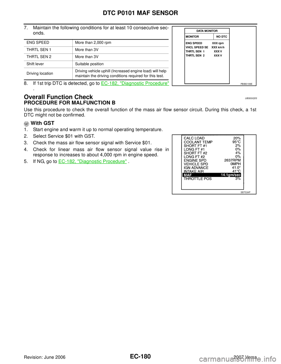
With GST
1. Start engine and warm it up to normal operating temperature.
2. Select Service $01 with GST.
3. Check the mass air flow sensor signal with Service $01.
4. Check for linear mass air flow sensor signal value rise in
response to increases to about 4,000 rpm in engine speed.
5. If NG, go to EC-182, "
Diagnostic Procedure" .
ENG SPEED More than 2,000 rpm
THRTL SEN 1 More than 3V
THRTL SEN 2 More than 3V
Shift lever Suitable position
Driving locationDriving vehicle uphill (Increased engine load) will help
maintain the driving conditions required for this test.
PBIB0199E
SEF 5 34 P