Page 1230 of 2896
 SYSTEM
EC-61
C
D
E
F
G
H
I
J
K
L
MA
EC
Revision: June 20062007 Versa
With GST
The emission related diagnostic information in the ECM can be erased by selecting Service $04 w")
ON BOARD DIAGNOSTIC (OBD) SYSTEM
EC-61
C
D
E
F
G
H
I
J
K
L
MA
EC
Revision: June 20062007 Versa
With GST
The emission related diagnostic information in the ECM can be erased by selecting Service $04 with GST.
NOTE:
If the DTC is not for A/T or CVT related items (see EC-8, "
INDEX FOR DTC" ), skip step 2.
1. If the ignition switch stays ON after repair work, be sure to turn ignition switch OFF once.
Wait at least 10 seconds and then turn it ON (engine stopped) again.
2. Perform AT- 4 1 , "
HOW TO ERASE DTC (WITH GST)" or CVT-32, "HOW TO ERASE DTC (WITH GST)"
(The DTC in the TCM will be erased.)
3. Select Service $04 with GST (Generic Scan Tool).
No Tools
NOTE:
If the DTC is not for A/T or CVT related items (see EC-8, "
INDEX FOR DTC" ), skip step 2.
1. If the ignition switch stays ON after repair work, be sure to turn ignition switch OFF once.
Wait at least 10 seconds and then turn it ON (engine stopped) again.
2. Perform AT-42, "
HOW TO ERASE DTC (NO TOOLS)" or CVT-31, "HOW TO ERASE DTC" . (The DTC in
the TCM will be erased.)
3. Change the diagnostic test mode from Mode II to Mode I by depressing the accelerator pedal.
Refer to EC-62, "
HOW TO SWITCH DIAGNOSTIC TEST MODE" .
�If the battery is disconnected, the emission-related diagnostic information will be lost within 24
hours.
�The following data are cleared when the ECM memory is erased.
–Diagnostic trouble codes
–1st trip diagnostic trouble codes
–Freeze frame data
–1st trip freeze frame data
–System readiness test (SRT) codes
–Test values
Actual work procedures are explained using a DTC as an example. Be careful so that not only the DTC, but all
of the data listed above, are cleared from the ECM memory during work procedures.
Malfunction Indicator Lamp (MIL)UBS00QBI
DESCRIPTION
The MIL is located on the instrument panel.
1. The MIL will light up when the ignition switch is turned ON with-
out the engine running. This is a bulb check.
If the MIL does not light up, refer to DI-24, "
WAR NI NG L AMPS"
or see EC-592, "MIL AND DATA LINK CONNECTOR" .
2. When the engine is started, the MIL should go off.
If the MIL remains on, the on board diagnostic system has
detected an engine system malfunction.
SEF 2 17 U
Page 1239 of 2896

EC-70Revision: June 2006
BASIC SERVICE PROCEDURE
2007 Versa
BASIC SERVICE PROCEDUREPFP:00018
Basic InspectionUBS00QBK
1. INSPECTION START
1. Check service records for any recent repairs that may indicate a related malfunction, or a current need for
scheduled maintenance.
2. Open engine hood and check the following:
–Harness connectors for improper connections
–Wiring harness for improper connections, pinches and cut
–Vacuum hoses for splits, kinks and improper connections
–Hoses and ducts for leaks
–Air cleaner clogging
–Gasket
3. Confirm that electrical or mechanical loads are not applied.
–Headlamp switch is OFF.
–Air conditioner switch is OFF. (Models with A/C)
–Rear window defogger switch is OFF.
–Steering wheel is in the straight-ahead position, etc.
4. Start engine and warm it up until engine coolant temperature
indicator points the middle of gauge.
Ensure engine stays below 1,000 rpm.
5. Run engine at about 2,000 rpm for about 2 minutes under no
load.
6. Make sure that no DTC is displayed with CONSULT-II or GST.
OK or NG
OK >> GO TO 3.
NG >> GO TO 2.
2. REPAIR OR REPLACE
Repair or replace components as necessary according to corresponding Diagnostic Procedure.
>> GO TO 3.
SEF 9 83 U
SEF 9 76 U
SEF 9 77 U
Page 1240 of 2896

BASIC SERVICE PROCEDURE
EC-71
C
D
E
F
G
H
I
J
K
L
MA
EC
Revision: June 20062007 Versa
3. CHECK TARGET IDLE SPEED
With CONSULT-II
1. Run engine at about 2,000 rpm for about 2 minutes under no load.
2. Rev engine (2,000 to 3,000 rpm) two or three times under no
load, then run engine at idle speed for about 1 minute.
3. Read idle speed in “DATA MONITOR” mode with CONSULT-II.
Refer to EC-75, "
IDLE SPEED" .
Without CONSULT-II
1. Run engine at about 2,000 rpm for about 2 minutes under no load.
2. Rev engine (2,000 to 3,000 rpm) two or three times under no load, then run engine at idle speed for about
1 minute.
3. Check idle speed. Refer to EC-75, "
IDLE SPEED" .
OK or NG
OK >> GO TO 10.
NG >> GO TO 4.
4. PERFORM ACCELERATOR PEDAL RELEASED POSITION LEARNING
1. Stop engine.
2. Perform EC-77, "
Accelerator Pedal Released Position Learning" .
>> GO TO 5.
5. PERFORM THROTTLE VALVE CLOSED POSITION LEARNING
Perform EC-78, "
Throttle Valve Closed Position Learning" .
>> GO TO 6.
SEF 9 78 U
M/T: 700 ± 50 rpm (in Neutral position)
A/T: 700 ± 50 rpm (in P or N position)
CVT: 700 ± 50 rpm (in P or N position)
SEF 0 58 Y
M/T: 700 ± 50 rpm (in Neutral position)
A/T: 700 ± 50 rpm (in P or N position)
CVT: 700 ± 50 rpm (in P or N position)
Page 1241 of 2896

EC-72Revision: June 2006
BASIC SERVICE PROCEDURE
2007 Versa
6. PERFORM IDLE AIR VOLUME LEARNING
Refer to EC-78, "
Idle Air Volume Learning" .
Is Idle Air Volume Learning carried out successfully?
Ye s o r N o
Yes >> GO TO 7.
No >> 1. Follow the instruction of Idle Air Volume Learning.
2. GO TO 4.
7. CHECK TARGET IDLE SPEED AGAIN
With CONSULT-II
1. Start engine and warm it up to normal operating temperature.
2. Read idle speed in “DATA MONITOR” mode with CONSULT-II.
Refer to EC-75, "
IDLE SPEED" .
Without CONSULT-II
1. Start engine and warm it up to normal operating temperature.
2. Check idle speed. Refer to EC-75, "
IDLE SPEED" .
OK or NG
OK >> GO TO 10.
NG >> GO TO 8.
8. DETECT MALFUNCTIONING PART
Check the following.
�Check crankshaft position sensor (POS) and circuit.
Refer to EC-319, "
DTC P0335 CKP SENSOR (POS)" .
�Check camshaft position sensor (PHASE) and circuit.
Refer to EC-327, "
DTC P0340 CMP SENSOR (PHASE)" .
OK or NG
OK >> GO TO 9.
NG >> 1. Repair or replace.
2. GO TO 4.
9. CHECK ECM FUNCTION
1. Substitute another known-good ECM to check ECM function. (ECM may be the cause of an incident, but
this is a rare case.)
2. Perform initialization of NVIS (NATS) system and registration of all NVIS (NATS) ignition key IDs.
Refer to BL-214, "
ECM Re-communicating Function" .
>> GO TO 4. M/T: 700 ± 50 rpm (in Neutral position)
A/T: 700 ± 50 rpm (in P or N position)
CVT: 700 ± 50 rpm (in P or N position)
M/T: 700 ± 50 rpm (in Neutral position)
A/T: 700 ± 50 rpm (in P or N position)
CVT: 700 ± 50 rpm (in P or N position)
SEF 1 74 Y
Page 1242 of 2896
BASIC SERVICE PROCEDURE
EC-73
C
D
E
F
G
H
I
J
K
L
MA
EC
Revision: June 20062007 Versa
10. CHECK IGNITION TIMING
1. Run engine at idle.
2. Check ignition timing with a timing light.
Refer to EC-75, "
IGNITION TIMING" .
–Timing indicator (1)
OK or NG
OK >> GO TO 19.
NG >> GO TO 11.
11 . PERFORM ACCELERATOR PEDAL RELEASED POSITION LEARNING
1. Stop engine.
2. Perform EC-77, "
Accelerator Pedal Released Position Learning" .
>> GO TO 12.
12. PERFORM THROTTLE VALVE CLOSED POSITION LEARNING
Perform EC-78, "
Throttle Valve Closed Position Learning" .
>> GO TO 13.
13. PERFORM IDLE AIR VOLUME LEARNING
Refer to EC-78, "
Idle Air Volume Learning" .
Is Idle Air Volume Learning carried out successfully?
Ye s o r N o
Yes >> GO TO 14.
No >> 1. Follow the instruction of Idle Air Volume Learning.
2. GO TO 4. M/T: 13 ± 5° BTDC (in Neutral position)
A/T: 13 ± 5° BTDC (in P or N position)
CVT: 13 ± 5° BTDC (in P or N position)
PBIB3263E
Page 1243 of 2896

EC-74Revision: June 2006
BASIC SERVICE PROCEDURE
2007 Versa
14. CHECK TARGET IDLE SPEED AGAIN
With CONSULT-II
1. Start engine and warm it up to normal operating temperature.
2. Read idle speed in “DATA MONITOR” mode with CONSULT-II.
Refer to EC-75, "
IDLE SPEED" .
Without CONSULT-II
1. Start engine and warm it up to normal operating temperature.
2. Check idle speed. Refer to EC-75, "
IDLE SPEED" .
OK or NG
OK >> GO TO 15.
NG >> GO TO 17.
15. CHECK IGNITION TIMING AGAIN
1. Run engine at idle.
2. Check ignition timing with a timing light.
Refer to EC-75, "
IGNITION TIMING" .
–Timing indicator (1)
OK or NG
OK >> GO TO 19
NG >> GO TO 16.
16. CHECK TIMING CHAIN INSTALLATION
Check timing chain installation. Refer to EM-37, "
TIMING CHAIN" .
OK or NG
OK >> GO TO 17.
NG >> 1. Repair the timing chain installation.
2. GO TO 4.
17. DETECT MALFUNCTIONING PART
Check the following.
�Check crankshaft position sensor (POS) and circuit.
Refer to EC-319, "
DTC P0335 CKP SENSOR (POS)" .
�Check camshaft position sensor (PHASE) and circuit.
Refer to EC-327, "
DTC P0340 CMP SENSOR (PHASE)" .
OK or NG
OK >> GO TO 18.
NG >> 1. Repair or replace.
2. GO TO 4. M/T: 700 ± 50 rpm (in Neutral position)
A/T: 700 ± 50 rpm (in P or N position)
CVT: 700 ± 50 rpm (in P or N position)
M/T: 700 ± 50 rpm (in Neutral position)
A/T: 700 ± 50 rpm (in P or N position)
CVT: 700 ± 50 rpm (in P or N position)
SEF 1 74 Y
M/T: 13 ± 5° BTDC (in Neutral position)
A/T: 13 ± 5° BTDC (in P or N position)
CVT: 13 ± 5° BTDC (in P or N position)
PBIB3263E
Page 1244 of 2896
BASIC SERVICE PROCEDURE
EC-75
C
D
E
F
G
H
I
J
K
L
MA
EC
Revision: June 20062007 Versa
18. CHECK ECM FUNCTION
1. Substitute another known-good ECM to check ECM function. (ECM may be the cause of an incident, but
this is a rare case.)
2. Perform initialization of NVIS (NATS) system and registration of all NVIS (NATS) ignition key IDs.
Refer to BL-214, "
ECM Re-communicating Function" .
>> GO TO 4.
19. INSPECTION END
Did you replace ECM, referring this Basic Inspection procedure?
Ye s o r N o
Ye s > > 1 . P e r f o r m EC-77, "VIN Registration" .
2.INSPECTION END
No >>INSPECTION END
Idle Speed and Ignition Timing CheckUBS00QBL
IDLE SPEED
With CONSULT-II
Check idle speed in “DATA MONITOR” mode with CONSULT-II.
With GST
Check idle speed in Service $01 with GST.
IGNITION TIMING
Any of following two methods may be used.
Method A
1. Attach timing light to loop wire (1) as shown.
� : Vehicle front
SEF 0 58 Y
PBIB3320E
Page 1245 of 2896
EC-76Revision: June 2006
BASIC SERVICE PROCEDURE
2007 Versa
2. Check ignition timing.
�Timing indicator (1)
Method B
1. Remove No. 4 ignition coil (1).
� : Vehicle front
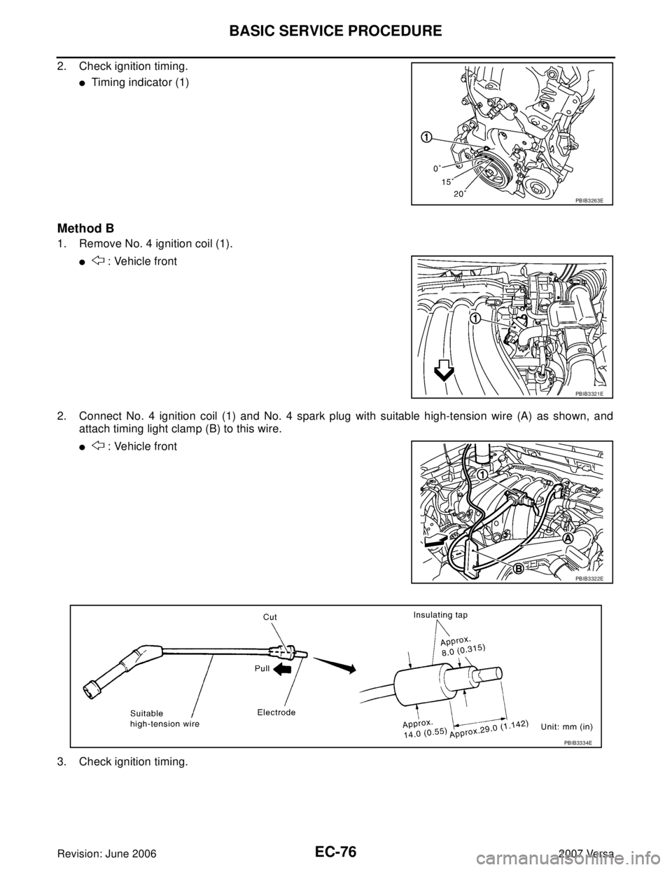
2. Connect No. 4 ignition coil (1) and No. 4 spark plug with suitable high-tension wire (A) as shown, and
attach timing light clamp (B) to this wire.
� : Vehicle front
3. Check ignition timing.
PBIB3263E
PBIB3321E
PBIB3322E
PBIB3334E