Page 220 of 1226

Camshaft Position Sensor (CMPS) (PUMP)
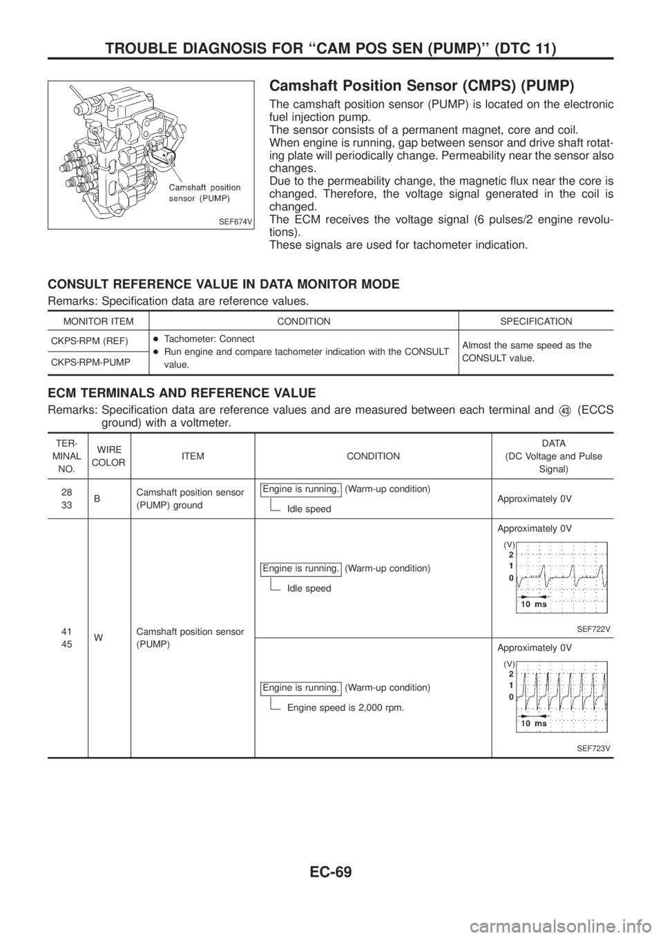
The camshaft position sensor (PUMP) is located on the electronic
fuel injection pump.
The sensor consists of a permanent magnet, core and coil.
When engine is running, gap between sensor and drive shaft rotat-
ing plate will periodically change. Permeability near the sensor also
changes.
Due to the permeability change, the magnetic ¯ux near the core is
changed. Therefore, the voltage signal generated in the coil is
changed.
The ECM receives the voltage signal (6 pulses/2 engine revolu-
tions).
These signals are used for tachometer indication.
CONSULT REFERENCE VALUE IN DATA MONITOR MODE
Remarks: Speci®cation data are reference values.
MONITOR ITEM CONDITION SPECIFICATION
CKPSzRPM (REF)+Tachometer: Connect
+Run engine and compare tachometer indication with the CONSULT
value.Almost the same speed as the
CONSULT value.
CKPSzRPM-PUMP
ECM TERMINALS AND REFERENCE VALUE
Remarks: Speci®cation data are reference values and are measured between each terminal andV43(ECCS
ground) with a voltmeter.
TER-
MINAL
NO.WIRE
COLORITEM CONDITIONDATA
(DC Voltage and Pulse
Signal)
28
33BCamshaft position sensor
(PUMP) groundEngine is running.
(Warm-up condition)
Idle speedApproximately 0V
41
45WCamshaft position sensor
(PUMP)Engine is running.
(Warm-up condition)
Idle speedApproximately 0V
SEF722V
Engine is running.(Warm-up condition)
Engine speed is 2,000 rpm.Approximately 0V
SEF723V
SEF674V
TROUBLE DIAGNOSIS FOR ``CAM POS SEN (PUMP)'' (DTC 11)
EC-69
Page 221 of 1226

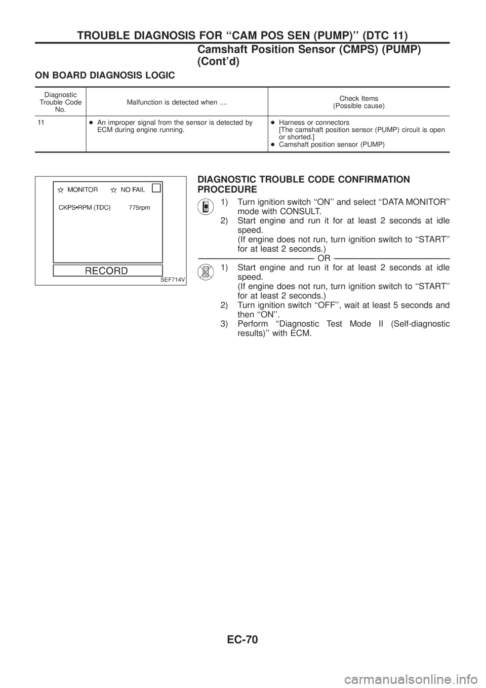
ON BOARD DIAGNOSIS LOGIC
Diagnostic
Trouble Code
No.Malfunction is detected when ....Check Items
(Possible cause)
11+An improper signal from the sensor is detected by
ECM during engine running.+Harness or connectors
[The camshaft position sensor (PUMP) circuit is open
or shorted.]
+Camshaft position sensor (PUMP)
DIAGNOSTIC TROUBLE CODE CONFIRMATION
PROCEDURE
1) Turn ignition switch ``ON'' and select ``DATA MONITOR''
mode with CONSULT.
2) Start engine and run it for at least 2 seconds at idle
speed.
(If engine does not run, turn ignition switch to ``START''
for at least 2 seconds.)
-------------------------------------------------------------------------------------------------------------------------------------------------------------------------------------------------------------------------------------------------------OR-------------------------------------------------------------------------------------------------------------------------------------------------------------------------------------------------------------------------------------------------------
1) Start engine and run it for at least 2 seconds at idle
speed.
(If engine does not run, turn ignition switch to ``START''
for at least 2 seconds.)
2) Turn ignition switch ``OFF'', wait at least 5 seconds and
then ``ON''.
3) Perform ``Diagnostic Test Mode II (Self-diagnostic
results)'' with ECM.
SEF714V
TROUBLE DIAGNOSIS FOR ``CAM POS SEN (PUMP)'' (DTC 11)
Camshaft Position Sensor (CMPS) (PUMP)
(Cont'd)
EC-70
Page 222 of 1226
TEC423
TROUBLE DIAGNOSIS FOR ``CAM POS SEN (PUMP)'' (DTC 11)
Camshaft Position Sensor (CMPS) (PUMP)
(Cont'd)
EC-71
Page 223 of 1226

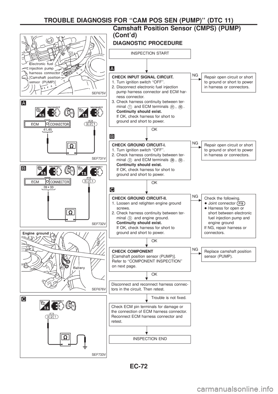
DIAGNOSTIC PROCEDURE
INSPECTION START
CHECK INPUT SIGNAL CIRCUIT.
1. Turn ignition switch ``OFF''.
2. Disconnect electronic fuel injection
pump harness connector and ECM har-
ness connector.
3. Check harness continuity between ter-
minal
V1and ECM terminalsV41,V45.
Continuity should exist.
If OK, check harness for short to
ground and short to power.
OK
cNG
Repair open circuit or short
to ground or short to power
in harness or connectors.
CHECK GROUND CIRCUIT-I.
1. Turn ignition switch ``OFF''.
2. Check harness continuity between ter-
minal
V2and ECM terminalsV28,V33.
Continuity should exist.
If OK, check harness for short to
ground and short to power.
OK
cNG
Repair open circuit or short
to ground or short to power
in harness or connectors.
CHECK GROUND CIRCUIT-II.
1. Loosen and retighten engine ground
screws.
2. Check harness continuity between ter-
minal
V3and engine ground.
Continuity should exist.
If OK, check harness for short to
ground and short to power.
OK
cNG
Check the following.
+Joint connector
F19
+Harness for open or
short between electronic
fuel injection pump and
engine ground
If NG, repair harness or
connectors.
CHECK COMPONENT
[Camshaft position sensor (PUMP)].
Refer to ``COMPONENT INSPECTION''
on next page.
OK
cNG
Replace camshaft position
sensor (PUMP).
Disconnect and reconnect harness connec-
tors in the circuit. Then retest.
Trouble is not ®xed.
Check ECM pin terminals for damage or
the connection of ECM harness connector.
Reconnect ECM harness connector and
retest.
INSPECTION END
SEF675V
SEF731V
SEF732V
SEF676V
SEF733V
.
.
.
.
.
.
.
TROUBLE DIAGNOSIS FOR ``CAM POS SEN (PUMP)'' (DTC 11)
Camshaft Position Sensor (CMPS) (PUMP)
(Cont'd)
EC-72
Page 224 of 1226
COMPONENT INSPECTION
Camshaft position sensor (PUMP)
1. Disconnect electronic fuel injection pump harness connector.
2. Loosen the camshaft position sensor (PUMP).
3. Remove the sensor.
4. Visually check the sensor for chipping.
5. Check resistance between terminals
V1andV2.
Resistance:
Approximately 1,360 - 1,840W[at 25ÉC (77ÉF)]
If NG, replace camshaft position sensor (PUMP).
SEF573S
SEF677V
TROUBLE DIAGNOSIS FOR ``CAM POS SEN (PUMP)'' (DTC 11)
Camshaft Position Sensor (CMPS) (PUMP)
(Cont'd)
EC-73
Page 225 of 1226

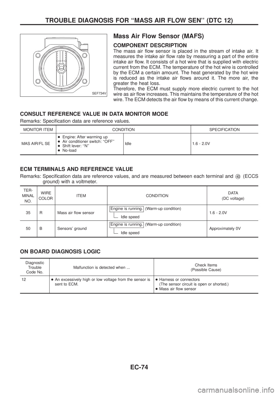
Mass Air Flow Sensor (MAFS)
COMPONENT DESCRIPTION
The mass air ¯ow sensor is placed in the stream of intake air. It
measures the intake air ¯ow rate by measuring a part of the entire
intake air ¯ow. It consists of a hot wire that is supplied with electric
current from the ECM. The temperature of the hot wire is controlled
by the ECM a certain amount. The heat generated by the hot wire
is reduced as the intake air ¯ows around it. The more air, the
greater the heat loss.
Therefore, the ECM must supply more electric current to the hot
wire as air ¯ow increases. This maintains the temperature of the hot
wire. The ECM detects the air ¯ow by means of this current change.
CONSULT REFERENCE VALUE IN DATA MONITOR MODE
Remarks: Speci®cation data are reference values.
MONITOR ITEM CONDITION SPECIFICATION
MAS AIR/FL SE+Engine: After warming up
+Air conditioner switch: ``OFF''
+Shift lever: ``N''
+No-loadIdle 1.6 - 2.0V
ECM TERMINALS AND REFERENCE VALUE
Remarks: Speci®cation data are reference values, and are measured between each terminal andV43(ECCS
ground) with a voltmeter.
TER-
MINAL
NO.WIRE
COLORITEM CONDITIONDATA
(DC voltage)
35 R Mass air ¯ow sensorEngine is running.
(Warm-up condition)
Idle speed1.6 - 2.0V
50 B Sensors' groundEngine is running.
(Warm-up condition)
Idle speedApproximately 0V
ON BOARD DIAGNOSIS LOGIC
Diagnostic
Trouble
Code No.Malfunction is detected when ...Check Items
(Possible Cause)
12+An excessively high or low voltage from the sensor is
sent to ECM.+Harness or connectors
(The sensor circuit is open or shorted.)
+Mass air ¯ow sensor
SEF734V
TROUBLE DIAGNOSIS FOR ``MASS AIR FLOW SEN'' (DTC 12)
EC-74
Page 226 of 1226

DIAGNOSTIC TROUBLE CODE CONFIRMATION
PROCEDURE
1) Turn ignition switch ``ON'', and wait at least 6 seconds.
2) Select ``DATA MONITOR'' mode with CONSULT.
3) Start engine and wait at least 3 seconds.
-------------------------------------------------------------------------------------------------------------------------------------------------------------------------------------------------------------------------------------------------------OR-------------------------------------------------------------------------------------------------------------------------------------------------------------------------------------------------------------------------------------------------------
1) Turn ignition switch ``ON'', and wait at least 6 seconds.
2) Start engine and wait at least 3 seconds.
3) Turn ignition switch ``OFF'', wait at least 5 seconds and
then turn ``ON''.
4) Perform ``Diagnostic Test Mode II (Self-diagnostic
results)'' with ECM.
SEF735V
TROUBLE DIAGNOSIS FOR ``MASS AIR FLOW SEN'' (DTC 12)
Mass Air Flow Sensor (MAFS) (Cont'd)
EC-75
Page 227 of 1226
TEC424
TROUBLE DIAGNOSIS FOR ``MASS AIR FLOW SEN'' (DTC 12)
Mass Air Flow Sensor (MAFS) (Cont'd)
EC-76