2006 NISSAN PATROL sensor
[x] Cancel search: sensorPage 70 of 1226
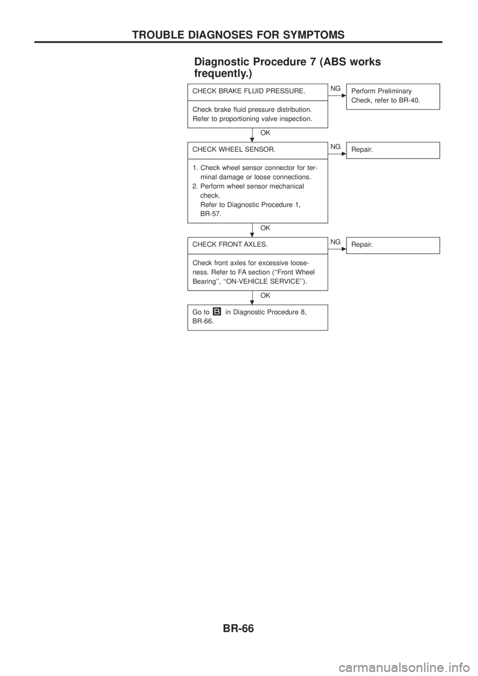
Diagnostic Procedure 7 (ABS works
frequently.)
CHECK BRAKE FLUID PRESSURE.
- ---------------------------------------------------------------------------------------------------------------------------------------------------------------------------------------------------------------------------------------------------------------------------------------------------------------
Check brake ¯uid pressure distribution.
Refer to proportioning valve inspection.
OK
cNG Perform Preliminary
Check, refer to BR-40.
CHECK WHEEL SENSOR.
- ---------------------------------------------------------------------------------------------------------------------------------------------------------------------------------------------------------------------------------------------------------------------------------------------------------------
1. Check wheel sensor connector for ter- minal damage or loose connections.
2. Perform wheel sensor mechanical check.
Refer to Diagnostic Procedure 1,
BR-57.
OK
cNG Repair.
CHECK FRONT AXLES.
- ---------------------------------------------------------------------------------------------------------------------------------------------------------------------------------------------------------------------------------------------------------------------------------------------------------------
Check front axles for excessive loose-
ness. Refer to FA section (``Front Wheel
Bearing'', ``ON-VEHICLE SERVICE'').
OK
cNG Repair.
Go toin Diagnostic Procedure 8,
BR-66.
.
.
.
TROUBLE DIAGNOSES FOR SYMPTOMS
BR-66
Page 71 of 1226
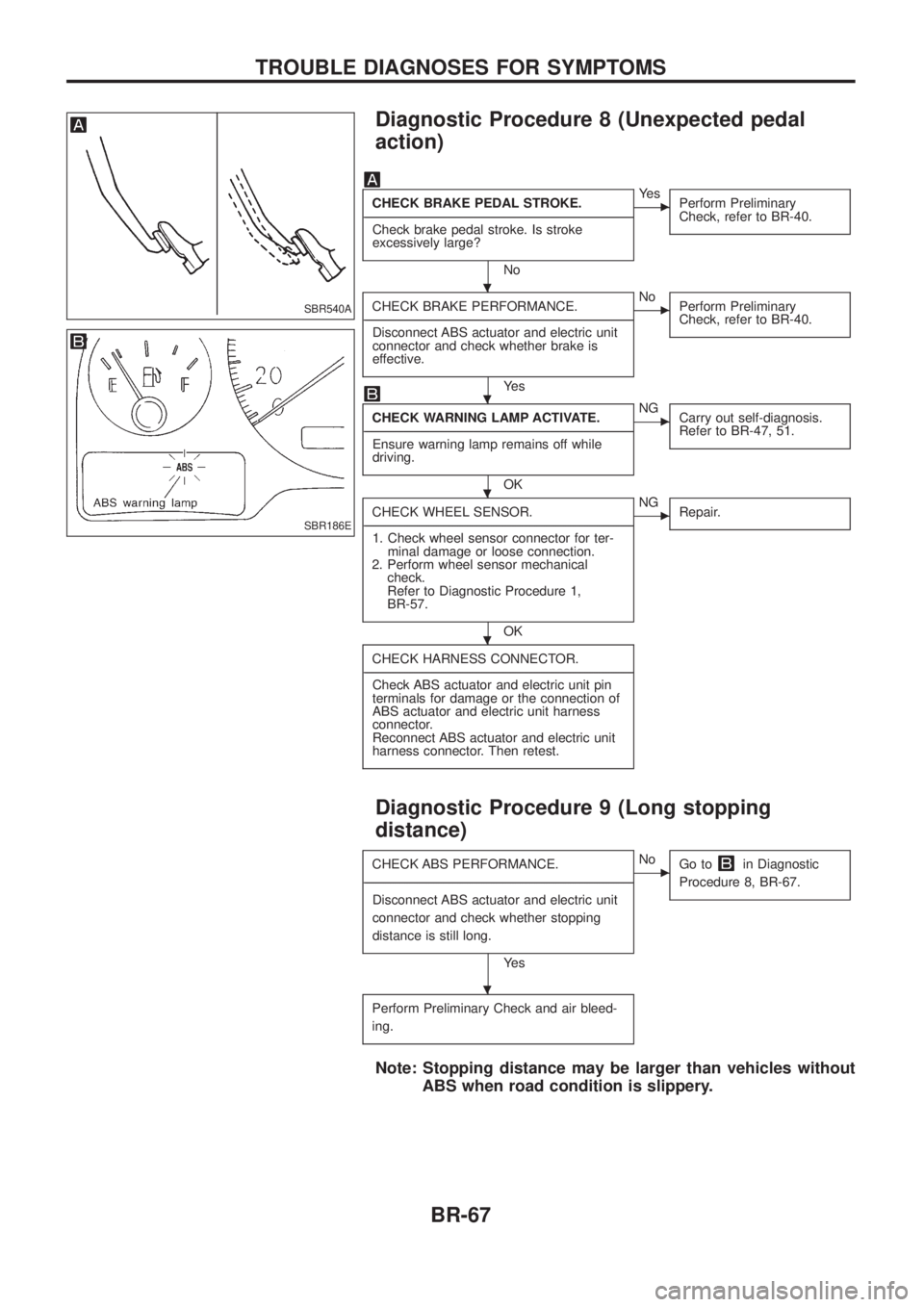
Diagnostic Procedure 8 (Unexpected pedal
action)
CHECK BRAKE PEDAL STROKE.
- ---------------------------------------------------------------------------------------------------------------------------------------------------------------------------------------------------------------------------------------------------------------------------------------------------------------
Check brake pedal stroke. Is stroke
excessively large?
No
cYe s Perform Preliminary
Check, refer to BR-40.
CHECK BRAKE PERFORMANCE.
- ---------------------------------------------------------------------------------------------------------------------------------------------------------------------------------------------------------------------------------------------------------------------------------------------------------------
Disconnect ABS actuator and electric unit
connector and check whether brake is
effective.
Ye s
cNo Perform Preliminary
Check, refer to BR-40.
CHECK WARNING LAMP ACTIVATE.
- ---------------------------------------------------------------------------------------------------------------------------------------------------------------------------------------------------------------------------------------------------------------------------------------------------------------
Ensure warning lamp remains off while
driving.
OK
cNG Carry out self-diagnosis.
Refer to BR-47, 51.
CHECK WHEEL SENSOR.
- ---------------------------------------------------------------------------------------------------------------------------------------------------------------------------------------------------------------------------------------------------------------------------------------------------------------
1. Check wheel sensor connector for ter- minal damage or loose connection.
2. Perform wheel sensor mechanical check.
Refer to Diagnostic Procedure 1,
BR-57.
OK
cNG Repair.
CHECK HARNESS CONNECTOR.
- ---------------------------------------------------------------------------------------------------------------------------------------------------------------------------------------------------------------------------------------------------------------------------------------------------------------
Check ABS actuator and electric unit pin
terminals for damage or the connection of
ABS actuator and electric unit harness
connector.
Reconnect ABS actuator and electric unit
harness connector. Then retest.
Diagnostic Procedure 9 (Long stopping
distance)
CHECK ABS PERFORMANCE.
- ---------------------------------------------------------------------------------------------------------------------------------------------------------------------------------------------------------------------------------------------------------------------------------------------------------------
Disconnect ABS actuator and electric unit
connector and check whether stopping
distance is still long.
Ye s
cNo Go toin Diagnostic
Procedure 8, BR-67.
Perform Preliminary Check and air bleed-
ing.
Note: Stopping distance may be larger than vehicles without ABS when road condition is slippery.
SBR540A
SBR186E
.
.
.
.
.
TROUBLE DIAGNOSES FOR SYMPTOMS
BR-67
Page 72 of 1226
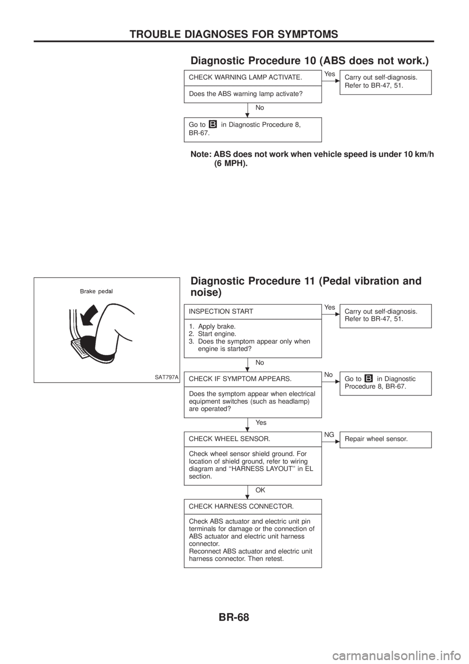
Diagnostic Procedure 10 (ABS does not work.)
CHECK WARNING LAMP ACTIVATE.
- ---------------------------------------------------------------------------------------------------------------------------------------------------------------------------------------------------------------------------------------------------------------------------------------------------------------
Does the ABS warning lamp activate?
No
cYe s Carry out self-diagnosis.
Refer to BR-47, 51.
Go toin Diagnostic Procedure 8,
BR-67.
Note: ABS does not work when vehicle speed is under 10 km/h (6 MPH).
Diagnostic Procedure 11 (Pedal vibration and
noise)
INSPECTION START
- ---------------------------------------------------------------------------------------------------------------------------------------------------------------------------------------------------------------------------------------------------------------------------------------------------------------
1. Apply brake.
2. Start engine.
3. Does the symptom appear only when engine is started?
No
cYe s Carry out self-diagnosis.
Refer to BR-47, 51.
CHECK IF SYMPTOM APPEARS.
- ---------------------------------------------------------------------------------------------------------------------------------------------------------------------------------------------------------------------------------------------------------------------------------------------------------------
Does the symptom appear when electrical
equipment switches (such as headlamp)
are operated?
Ye s
cNo Go toin Diagnostic
Procedure 8, BR-67.
CHECK WHEEL SENSOR.
- ---------------------------------------------------------------------------------------------------------------------------------------------------------------------------------------------------------------------------------------------------------------------------------------------------------------
Check wheel sensor shield ground. For
location of shield ground, refer to wiring
diagram and ``HARNESS LAYOUT'' in EL
section.
OK
cNG Repair wheel sensor.
CHECK HARNESS CONNECTOR.
- ---------------------------------------------------------------------------------------------------------------------------------------------------------------------------------------------------------------------------------------------------------------------------------------------------------------
Check ABS actuator and electric unit pin
terminals for damage or the connection of
ABS actuator and electric unit harness
connector.
Reconnect ABS actuator and electric unit
harness connector. Then retest.
SAT797A
.
.
.
.
TROUBLE DIAGNOSES FOR SYMPTOMS
BR-68
Page 79 of 1226

Service Notice
+When removing or installing various parts, place a cloth or padding onto the vehicle body to prevent
scratches.
+Handle trim, molding, instruments, grille, etc. carefully during removing or installing. Be careful not to soil
or damage them.
+Apply sealing compound where necessary when installing parts.
+When applying sealing compound, be careful that the sealing compound does not protrude from parts.
+When replacing any metal parts (for example body outer panel, members, etc.), be sure to take rust pre-
vention measures.
Supplemental Restraint System (SRS) ``AIR
BAG'' and ``SEAT BELT PRE-TENSIONER''
The Supplemental Restraint System such as ``AIR BAG'' and ``SEAT BELT PRE-TENSIONER'' used along with
a seat belt, helps to reduce the risk or severity of injury to the driver and front passenger in a frontal collision.
The SRS system composition which is available to NISSAN MODEL Y61 is as follows (The composition var-
ies according to the destination.):
Driver air bag module (located in the center of the steering wheel), front passenger air bag module (located
on the instrument panel on passenger side), seat belt pre-tensioner, a diagnosis sensor unit, warning lamp,
wiring harness and spiral cable.
Information necessary to service the system safely is included in theRS sectionof this Service Manual.
WARNING:
+To avoid rendering the SRS inoperative, which could increase the risk of personal injury or death
in the event of a collision which would result in air bag in¯ation, all maintenance must be performed
by an authorized NISSAN dealer.
+Improper maintenance, including incorrect removal and installation of the SRS, can lead to per-
sonal injury caused by unintentional activation of the system. For removal of Spiral Cable and Air
Bag Module, see the RS section.
+Do not use electrical test equipment on any circuit related to the SRS unless instructed to in this
Service Manual. Spiral cable and wiring harnesses covered with yellow insulation either just before
the harness connectors or for the complete harness are related to the SRS.
PRECAUTIONS
BT-1
Page 89 of 1226

CAUTION:
+Disconnect both battery cables in advance.
+Disconnect air bag system line in advance.
+Never tamper with or force air bag lid open, as this may adversely affect air bag performance.
+Be careful not to scratch pad and other parts.
REMOVAL Ð Instrument panel assembly
Instrument panel assemblyCombination meterAudio & A/C controlConsole box
Remove air bag module (driver) and steering wheel.
Refer to ``SUPPLEMENTAL RESTRAINT SYSTEM'' in RS section for details.
Remove dash side lower ®nishers.
Refer to ``Side and Floor Trim'' in ``INTERIOR TRIM'' for
details, BT-14.
V1Steering column cover and combination switch
+Remove screws.
V2Lower instrument panel on driver side
+Remove bolts and screws.
V3Cluster lid A
+Remove screws then disconnect harness connectors.
V4Combination meter
+Remove screws then disconnect harness connectors.
V5Cluster lid C
+Pull out then disconnect harness connectors.
+Remove screws then remove in-vehicle sensor.
V6Audio
+Remove screws then disconnect harness connectors.
V7A/C control unit
+Remove screws then disconnect harness connectors.
V8Console M/T or A/T ®nisher
+Remove screws then disconnect harness connectors.
V9Console box assembly
+Remove screws then disconnect harness connectors.
V10Instrument panel stay cover
+Remove screws then disconnect harness con-
nectors.
V11Glove box assembly and lower instrument panel on
passenger side
+Remove screws.
V12Passenger air bag module
+Refer to ``SUPPLEMENTAL RESTRAINT SYS-
TEM'' in RS section.
V13Mirror control switch
+Disconnect harness connector.
Remove front pillar garnish.
Refer to ``Side and Floor Trim'' in ``INTERIOR TRIM'' for
details, BT-14.
V14Mask instrument LH/RH or sensors.
+Disconnect harness connectors (models with
sensors).
V15Instrument panel and pads
+Remove bolts and nuts then disconnect harness
connectors.
INSTRUMENT PANEL
BT-11
Page 150 of 1226
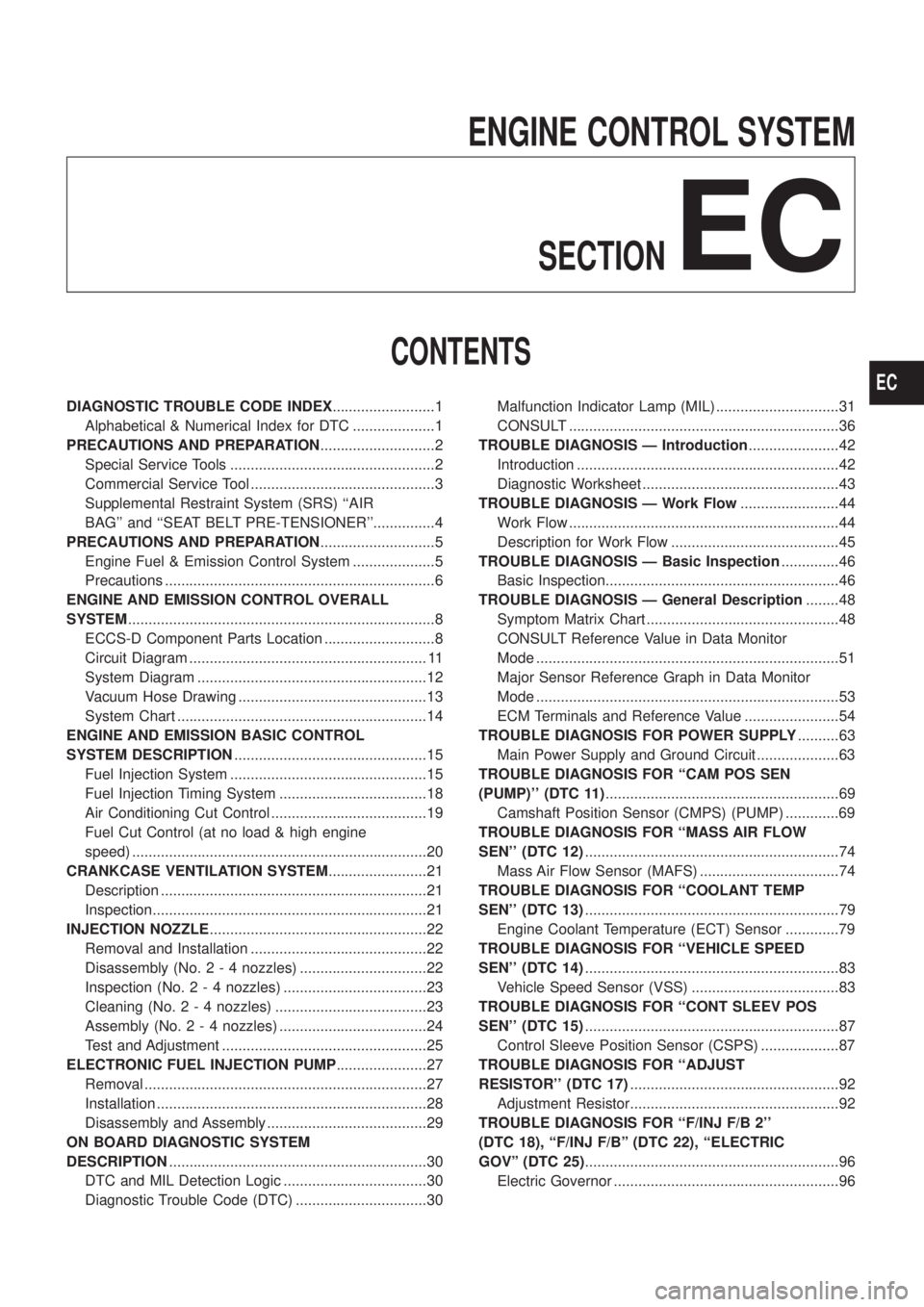
ENGINE CONTROL SYSTEMSECTION
EC
CONTENTS
DIAGNOSTIC TROUBLE CODE INDEX .........................1
Alphabetical & Numerical Index for DTC ....................1
PRECAUTIONS AND PREPARATION ............................2
Special Service Tools ..................................................2
Commercial Service Tool .............................................3
Supplemental Restraint System (SRS) ``AIR
BAG'' and ``SEAT BELT PRE-TENSIONER''...............4
PRECAUTIONS AND PREPARATION ............................5
Engine Fuel & Emission Control System ....................5
Precautions ..................................................................6
ENGINE AND EMISSION CONTROL OVERALL
SYSTEM ........................................................................\
...8
ECCS-D Component Parts Location ...........................8
Circuit Diagram .......................................................... 11
System Diagram ........................................................12
Vacuum Hose Drawing ..............................................13
System Chart .............................................................14
ENGINE AND EMISSION BASIC CONTROL
SYSTEM DESCRIPTION ...............................................15
Fuel Injection System ................................................15
Fuel Injection Timing System ....................................18
Air Conditioning Cut Control ......................................19
Fuel Cut Control (at no load & high engine
speed) ........................................................................\
20
CRANKCASE VENTILATION SYSTEM ........................21
Description .................................................................21
Inspection...................................................................21
INJECTION NOZZLE .....................................................22
Removal and Installation ...........................................22
Disassembly (No. 2 - 4 nozzles) ...............................22
Inspection (No. 2 - 4 nozzles) ...................................23
Cleaning (No. 2 - 4 nozzles) .....................................23
Assembly (No. 2 - 4 nozzles) ....................................24
Test and Adjustment ..................................................25
ELECTRONIC FUEL INJECTION PUMP ......................27
Removal .....................................................................27
Installation ..................................................................28
Disassembly and Assembly .......................................29
ON BOARD DIAGNOSTIC SYSTEM
DESCRIPTION ...............................................................30
DTC and MIL Detection Logic ...................................30
Diagnostic Trouble Code (DTC) ................................30 Malfunction Indicator Lamp (MIL) ..............................31
CONSULT ..................................................................36
TROUBLE DIAGNOSIS Ð Introduction ......................42
Introduction ................................................................42
Diagnostic Worksheet ................................................43
TROUBLE DIAGNOSIS Ð Work Flow ........................44
Work Flow ..................................................................44
Description for Work Flow .........................................45
TROUBLE DIAGNOSIS Ð Basic Inspection ..............46
Basic Inspection.........................................................46
TROUBLE DIAGNOSIS Ð General Description ........48
Symptom Matrix Chart ...............................................48
CONSULT Reference Value in Data Monitor
Mode ........................................................................\
..51
Major Sensor Reference Graph in Data Monitor
Mode ........................................................................\
..53
ECM Terminals and Reference Value .......................54
TROUBLEDIAGNOSISFORPOWERSUPPLY ..........63
MainPowerSupplyandGroundCircuit....................63
TROUBLE DIAGNOSIS FOR ``CAM POS SEN
(PUMP)''(DTC11) .........................................................69
CamshaftPositionSensor(CMPS)(PUMP).............69
TROUBLEDIAGNOSISFOR``MASSAIRFLOW
SEN''(DTC12) ..............................................................74
MassAirFlowSensor(MAFS)..................................74
TROUBLEDIAGNOSISFOR``COOLANTTEMP
SEN''(DTC13) ..............................................................79
EngineCoolantTemperature(ECT)Sensor.............79
TROUBLEDIAGNOSISFOR``VEHICLESPEED
SEN''(DTC14) ..............................................................83
VehicleSpeedSensor(VSS)....................................83
TROUBLEDIAGNOSISFOR``CONTSLEEVPOS
SEN''(DTC15) ..............................................................87
ControlSleevePositionSensor(CSPS)...................87
TROUBLEDIAGNOSISFOR``ADJUST
RESISTOR''(DTC17) ...................................................92
AdjustmentResistor...................................................92
TROUBLEDIAGNOSISFOR``F/INJF/B2''
(DTC18),``F/INJF/B''(DTC22),``ELECTRIC
GOV''(DTC25) ..............................................................96
ElectricGovernor.......................................................96
EC
Page 151 of 1226
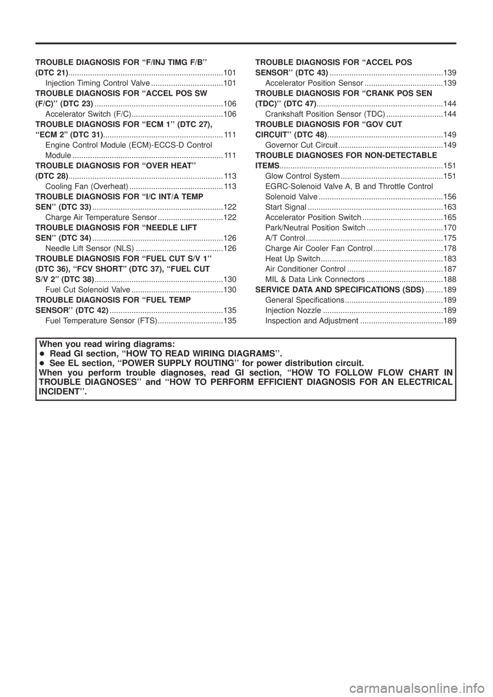
TROUBLEDIAGNOSISFOR``F/INJTIMGF/B''
(DTC21).......................................................................101
InjectionTimingControlValve.................................101
TROUBLEDIAGNOSISFOR``ACCELPOSSW
(F/C)''(DTC23) ...........................................................106
AcceleratorSwitch(F/C)..........................................106
TROUBLEDIAGNOSISFOR``ECM1''(DTC27),
``ECM2''(DTC31) .......................................................111
EngineControlModule(ECM)-ECCS-DControl
Module.....................................................................111
TROUBLEDIAGNOSISFOR``OVERHEAT''
(DTC28) .......................................................................113
CoolingFan(Overheat)...........................................113
TROUBLEDIAGNOSISFOR``I/CINT/ATEMP
SEN''(DTC33) ............................................................122
ChargeAirTemperatureSensor..............................122
TROUBLEDIAGNOSISFOR``NEEDLELIFT
SEN''(DTC34) ............................................................126
NeedleLiftSensor(NLS)........................................126
TROUBLE DIAGNOSIS FOR ``FUEL CUT S/V 1''
(DTC 36), ``FCV SHORT'' (DTC 37), ``FUEL CUT
S/V2''(DTC38) ...........................................................130
FuelCutSolenoidValve..........................................130
TROUBLE DIAGNOSIS FOR ``FUEL TEMP
SENSOR''(DTC42) ....................................................135
FuelTemperatureSensor(FTS)..............................135 TROUBLE DIAGNOSIS FOR ``ACCEL POS
SENSOR''(DTC43)
....................................................139
AcceleratorPositionSensor....................................139
TROUBLE DIAGNOSIS FOR ``CRANK POS SEN
(TDC)''(DTC47) ..........................................................144
CrankshaftPositionSensor(TDC)..........................144
TROUBLEDIAGNOSISFOR``GOVCUT
CIRCUIT''(DTC48) .....................................................149
GovernorCutCircuit................................................149
TROUBLEDIAGNOSESFORNON-DETECTABLE
ITEMS ........................................................................\
...151
GlowControlSystem...............................................151
EGRC-SolenoidValveA,BandThrottleControl
SolenoidValve.........................................................156
StartSignal..............................................................163
AcceleratorPositionSwitch.....................................165
Park/NeutralPositionSwitch...................................170
A/TControl...............................................................175
ChargeAirCoolerFanControl................................178
HeatUpSwitch........................................................183
AirConditionerControl............................................187
MIL&DataLinkConnectors...................................188
SERVICEDATAANDSPECIFICATIONS(SDS) ........189
GeneralSpeci®cations.............................................189
InjectionNozzle.......................................................189
InspectionandAdjustment......................................189
When you read wiring diagrams:
+ Read GI section, ``HOW TO READ WIRING DIAGRAMS''.
+ See EL section, ``POWER SUPPLY ROUTING'' for power distribution circuit.
When you perform trouble diagnoses, read GI section, ``HOW TO FOLLOW FLOW CHART IN
TROUBLE DIAGNOSES'' and ``HOW TO PERFORM EFFICIENT DIAGNOSIS FOR AN ELECTRICAL
INCIDENT''.
Page 152 of 1226
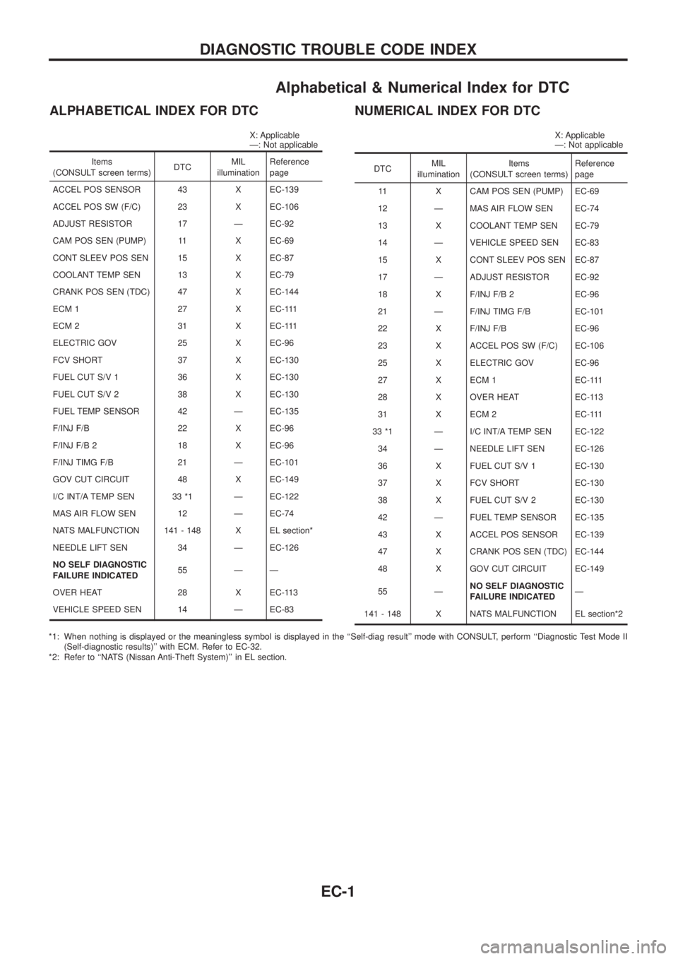
Alphabetical & Numerical Index for DTC
ALPHABETICAL INDEX FOR DTC
X: Applicable
Ð: Not applicable
Items
(CONSULT screen terms) DTCMIL
illumination Reference
page
ACCEL POS SENSOR 43 X EC-139
ACCEL POS SW (F/C) 23 X EC-106
ADJUST RESISTOR 17 Ð EC-92
CAM POS SEN (PUMP) 11 X EC-69
CONT SLEEV POS SEN 15 X EC-87
COOLANT TEMP SEN 13 X EC-79
CRANK POS SEN (TDC) 47 X EC-144
ECM 1 27 X EC-111
ECM 2 31 X EC-111
ELECTRIC GOV 25 X EC-96
FCV SHORT 37 X EC-130
FUEL CUT S/V 1 36 X EC-130
FUEL CUT S/V 2 38 X EC-130
FUEL TEMP SENSOR 42 Ð EC-135
F/INJ F/B 22 X EC-96
F/INJ F/B 2 18 X EC-96
F/INJ TIMG F/B 21 Ð EC-101
GOV CUT CIRCUIT 48 X EC-149
I/C INT/A TEMP SEN 33 *1 Ð EC-122
MAS AIR FLOW SEN 12 Ð EC-74
NATS MALFUNCTION 141 - 148 X EL section*
NEEDLE LIFT SEN 34 Ð EC-126
NO SELF DIAGNOSTIC
FAILURE INDICATED 55 Ð Ð
OVER HEAT 28 X EC-113
VEHICLE SPEED SEN 14 Ð EC-83
NUMERICAL INDEX FOR DTC
X: Applicable
Ð: Not applicable
DTC MIL
illumination Items
(CONSULT screen terms) Reference
page
11 X CAM POS SEN (PUMP) EC-69
12 Ð MAS AIR FLOW SEN EC-74
13 X COOLANT TEMP SEN EC-79
14 Ð VEHICLE SPEED SEN EC-83
15 X CONT SLEEV POS SEN EC-87
17 Ð ADJUST RESISTOR EC-92
18 X F/INJ F/B 2 EC-96
21 Ð F/INJ TIMG F/B EC-101
22 X F/INJ F/B EC-96
23 X ACCEL POS SW (F/C) EC-106
25 X ELECTRIC GOV EC-96
27 X ECM 1 EC-111
28 X OVER HEAT EC-113
31 X ECM 2 EC-111
33 *1 Ð I/C INT/A TEMP SEN EC-122 34 Ð NEEDLE LIFT SEN EC-126
36 X FUEL CUT S/V 1 EC-130
37 X FCV SHORT EC-130
38 X FUEL CUT S/V 2 EC-130
42 Ð FUEL TEMP SENSOR EC-135
43 X ACCEL POS SENSOR EC-139
47 X CRANK POS SEN (TDC) EC-144
48 X GOV CUT CIRCUIT EC-149
55 Ð NO SELF DIAGNOSTIC
FAILURE INDICATED Ð
141 - 148 X NATS MALFUNCTION EL section*2
*1: When nothing is displayed or the meaningless symbol is displayed in the ``Self-diag result'' mode with CONSULT, perform ``Diagnostic Test Mode II (Self-diagnostic results)'' with ECM. Refer to EC-32.
*2: Refer to ``NATS (Nissan Anti-Theft System)'' in EL section.
DIAGNOSTIC TROUBLE CODE INDEX
EC-1