Page 673 of 1226

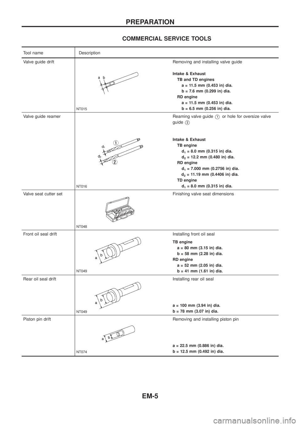
COMMERCIAL SERVICE TOOLS
Tool name Description
Valve guide drift
NT015
Removing and installing valve guide
Intake & Exhaust
TB and TD engines
a = 11.5 mm (0.453 in) dia.
b = 7.6 mm (0.299 in) dia.
RD engine
a = 11.5 mm (0.453 in) dia.
b = 6.5 mm (0.256 in) dia.
Valve guide reamer
NT016
Reaming valve guideV1or hole for oversize valve
guide
V2
Intake & Exhaust
TB engine
d
1= 8.0 mm (0.315 in) dia.
d
2= 12.2 mm (0.480 in) dia.
RD engine
d
1= 7.000 mm (0.2756 in) dia.
d
2= 11.19 mm (0.4406 in) dia.
TD engine
d
1= 8.0 mm (0.315 in) dia.
Valve seat cutter set
NT048
Finishing valve seat dimensions
Front oil seal drift
NT049
Installing front oil seal
TB engine
a = 80 mm (3.15 in) dia.
b = 58 mm (2.28 in) dia.
RD engine
a = 52 mm (2.05 in) dia.
b = 41 mm (1.61 in) dia.
Rear oil seal drift
NT049
Installing rear oil seal
a = 100 mm (3.94 in) dia.
b = 78 mm (3.07 in) dia.
Piston pin drift
NT074
Removing and installing piston pin
a = 22.5 mm (0.886 in) dia.
b = 12.5 mm (0.492 in) dia.
PREPARATION
EM-5
Page 676 of 1226

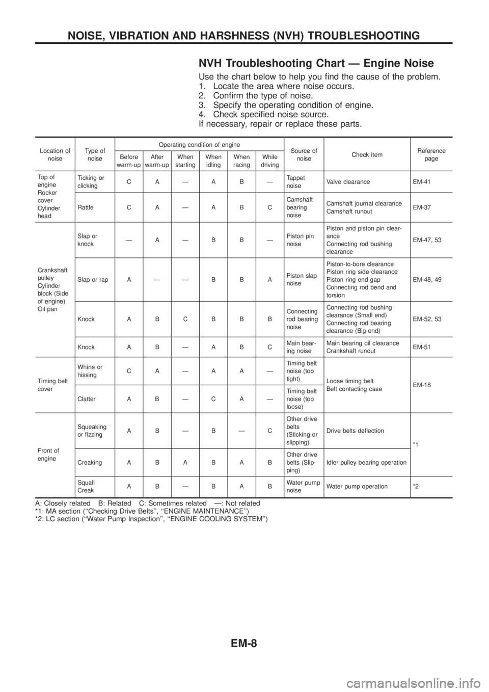
NVH Troubleshooting Chart Ð Engine Noise
Use the chart below to help you ®nd the cause of the problem.
1. Locate the area where noise occurs.
2. Con®rm the type of noise.
3. Specify the operating condition of engine.
4. Check speci®ed noise source.
If necessary, repair or replace these parts.
Location of
noiseType of
noiseOperating condition of engine
Source of
noiseCheck itemReference
page Before
warm-upAfter
warm-upWhen
startingWhen
idlingWhen
racingWhile
driving
To p o f
engine
Rocker
cover
Cylinder
headTicking or
clickingCAÐABÐTappet
noiseValve clearance EM-41
Rattle C A Ð A B CCamshaft
bearing
noiseCamshaft journal clearance
Camshaft runoutEM-37
Crankshaft
pulley
Cylinder
block (Side
of engine)
Oil panSlap or
knockÐAÐB BÐPiston pin
noisePiston and piston pin clear-
ance
Connecting rod bushing
clearanceEM-47, 53
Slap or rap A Ð Ð B B APiston slap
noisePiston-to-bore clearance
Piston ring side clearance
Piston ring end gap
Connecting rod bend and
torsionEM-48, 49
Knock A B C B B BConnecting
rod bearing
noiseConnecting rod bushing
clearance (Small end)
Connecting rod bearing
clearance (Big end)EM-52, 53
Knock A B Ð A B CMain bear-
ing noiseMain bearing oil clearance
Crankshaft runoutEM-51
Timing belt
coverWhine or
hissingCAÐAAÐTiming belt
noise (too
tight)
Loose timing belt
Belt contacting caseEM-18
Clatter A B Ð C A ÐTiming belt
noise (too
loose)
Front of
engineSqueaking
or ®zzingABÐBÐCOther drive
belts
(Sticking or
slipping)Drive belts de¯ection
*1
CreakingABABABOther drive
belts (Slip-
ping)Idler pulley bearing operation
Squall
CreakABÐBABWater pump
noiseWater pump operation *2
A: Closely related B: Related C: Sometimes related Ð: Not related
*1: MA section (``Checking Drive Belts'', ``ENGINE MAINTENANCE'')
*2: LC section (``Water Pump Inspection'', ``ENGINE COOLING SYSTEM'')
NOISE, VIBRATION AND HARSHNESS (NVH) TROUBLESHOOTING
EM-8
Page 680 of 1226

6. Fit compression gauge adapter to cylinder head.
7. Crank engine and read gauge indication.
Crank speed: 200 rpm
Compression pressure:
Standard
3,040 kPa (30.4 bar, 31 kg/cm
2, 441 psi)
Limit
2,452 kPa (24.5 bar, 25 kg/cm
2, 356 psi)
Differential limit between cylinders
490 kPa (4.9 bar, 5 kg/cm
2, 71 psi)
8. If the pressure appears low, pour about 3 m!(0.11 Imp ¯ oz)
of engine oil through nozzle holes and repeat test.
For indications of test, refer to the following table.
Gauge indication during tests Trouble diagnosis
SEM857
+Piston rings are worn or
damaged.
SEM858
+If two adjacent cylinders
are low, gasket is dam-
aged.
+Valve is sticking.
+Valve seat or valve con-
tact surface is incorrected.
9. Replace nozzle gaskets and install injection nozzles.
New nozzle gasket installation direction is as shown.
Nozzle to cylinder head:
:59-69Nzm
(6.0 - 7.0 kg-m, 43 - 51 ft-lb)
SEM706B
SEM708B
COMPRESSION PRESSURE
Measurement of Compression Pressure
(Cont'd)
EM-12
First readingSecond
reading
Increased
reading
Same reading
maintained
Page 682 of 1226
Removal
1. Remove oil pan guard.
2. Drain engine oil.
+When installing drain plug washer, ensure it faces in correct
direction.
+Discard oil drain plug washer and install a new one.
Drain plug:
:29-39Nzm (3.0 - 4.0 kg-m, 22 - 29 ft-lb)
SEM782F
SEM783F
SEM063B
OIL PAN
EM-14
Page 683 of 1226
3. Remove engine gussets and oil pan bolts.
+Remove bolts/nuts in numerical order shown in ®gure, alternat-
ing left and right ones toward the center.
4. Remove oil pump assembly.
Installation
Always install with new oil seal.
1. Install oil pump assembly.
Location Bolt length mm (in)
V120 (0.79)
V235 (1.38)
V345 (1.77)
V455 (2.17)
2. Install oil pan. Tighten bolts in the order shown in the ®gure.
+Always replace oil pan gaskets with new ones when reas-
sembling.
+Install oil pan gasket after cleaning the contacting surface.
+Oil pan bolts/nuts:
Bolt
:8-12Nzm (0.8 - 1.2 kg-m, 69 - 104 in-lb)
Nut
:10-14Nzm (1.0 - 1.4 kg-m, 87 - 122 in-lb)
3. Install engine gusset and oil pan guard.
SEM739B
SEM432C
SEM794F
SEM739BA
OIL PAN
Removal (Cont'd)
EM-15
Page 684 of 1226
CAUTION:
+Do not bend or twist timing belt.
+After removing timing belt, do not turn crankshaft and
camshaft separately because valves will strike piston
heads.
+Make sure that timing belt, camshaft sprocket, crankshaft
sprocket, idler pulley, injection pump pulley and belt ten-
sioner are clean and free from oil and water.
+Align white lines on timing belt with punch mark on cam-
shaft sprocket, crankshaft sprocket and injection pump
pulley.
+Installation should be carried out when engine is cold.
Removal
1. Remove radiator shroud.
2. Remove the following belts.
+Power steering drive belt
+A/C compressor drive belt
+Alternator drive belt
3. Remove cooling fan coupling and water pump pulley.
SMA767BA
TIMING BELT
EM-16
Page 686 of 1226

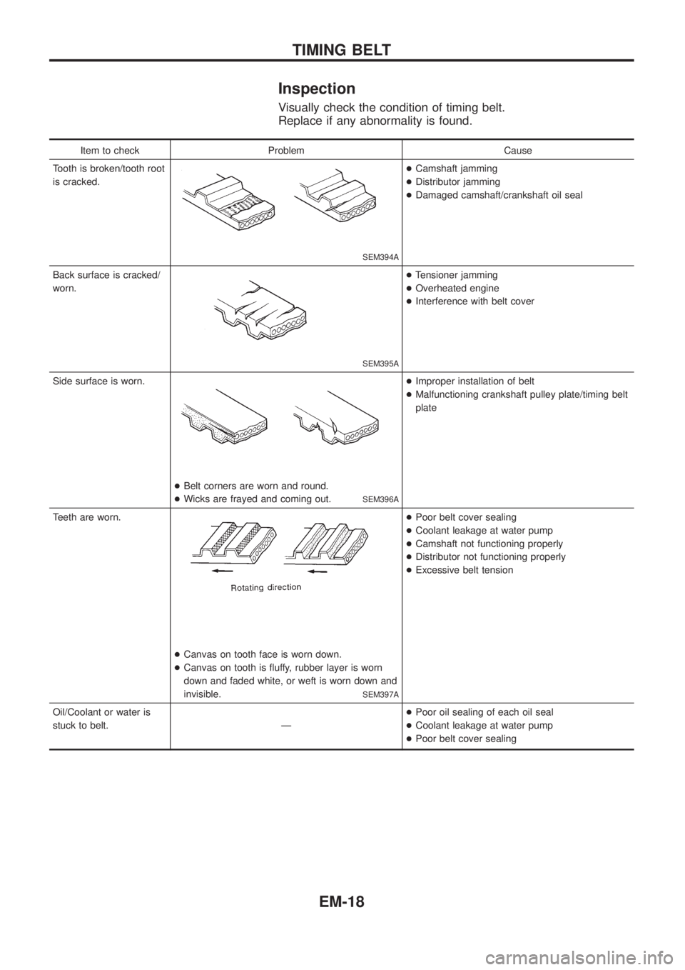
Inspection
Visually check the condition of timing belt.
Replace if any abnormality is found.
Item to check Problem Cause
Tooth is broken/tooth root
is cracked.
SEM394A
+Camshaft jamming
+Distributor jamming
+Damaged camshaft/crankshaft oil seal
Back surface is cracked/
worn.
SEM395A
+Tensioner jamming
+Overheated engine
+Interference with belt cover
Side surface is worn.
+Belt corners are worn and round.
+Wicks are frayed and coming out.
SEM396A
+Improper installation of belt
+Malfunctioning crankshaft pulley plate/timing belt
plate
Teeth are worn.
+Canvas on tooth face is worn down.
+Canvas on tooth is ¯uffy, rubber layer is worn
down and faded white, or weft is worn down and
invisible.
SEM397A
+Poor belt cover sealing
+Coolant leakage at water pump
+Camshaft not functioning properly
+Distributor not functioning properly
+Excessive belt tension
Oil/Coolant or water is
stuck to belt. Ð+Poor oil sealing of each oil seal
+Coolant leakage at water pump
+Poor belt cover sealing
TIMING BELT
EM-18
Page 687 of 1226
Installation
1. Con®rm that No. 1 cylinder is set at BDC on its expansion
stroke as follows:
Con®rm that crankshaft key is at the bottom.
2. Set timing belt.
a. Ensure timing belt, sprockets and pulleys are clean and
free from oil or water. Do not bend or twist timing belt too
much.
b. Align white lines on timing belt with matching mark on
camshaft sprocket, crankshaft sprocket and injection
pump pulley.
c. Point arrow on timing belt toward front.
SMA771B
TIMING BELT
EM-19