2006 NISSAN PATROL oil
[x] Cancel search: oilPage 509 of 1226
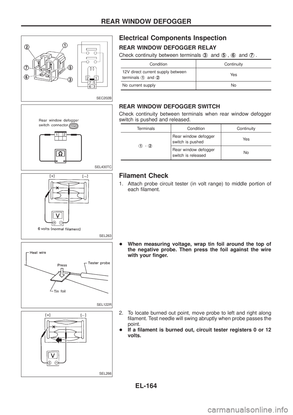
Electrical Components Inspection
REAR WINDOW DEFOGGER RELAY
Check continuity between terminalsj3andj5,j6andj7.
Condition Continuity
12V direct current supply between
terminalsj
1andj2Ye s
No current supply No
REAR WINDOW DEFOGGER SWITCH
Check continuity between terminals when rear window defogger
switch is pushed and released.
Terminals Condition Continuity
j
1-j2
Rear window defogger
switch is pushedYe s
Rear window defogger
switch is releasedNo
Filament Check
1. Attach probe circuit tester (in volt range) to middle portion of
each ®lament.
+When measuring voltage, wrap tin foil around the top of
the negative probe. Then press the foil against the wire
with your ®nger.
2. To locate burned out point, move probe to left and right along
®lament. Test needle will swing abruptly when probe passes the
point.
+If a ®lament is burned out, circuit tester registers 0 or 12
volts.
SEC202B
SEL430TC
SEL263
SEL122R
SEL266
REAR WINDOW DEFOGGER
EL-164
Page 517 of 1226
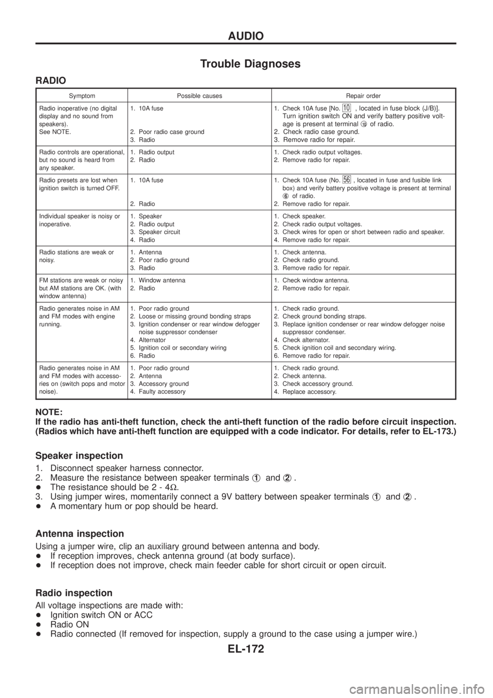
Trouble Diagnoses
RADIO
Symptom Possible causes Repair order
Radio inoperative (no digital
display and no sound from
speakers).
See NOTE.1. 10A fuse
2. Poor radio case ground
3. Radio1. Check 10A fuse [No.
10, located in fuse block (J/B)].
Turn ignition switch ON and verify battery positive volt-
age is present at terminalj
10of radio.
2. Check radio case ground.
3. Remove radio for repair.
Radio controls are operational,
but no sound is heard from
any speaker.1. Radio output
2. Radio1. Check radio output voltages.
2. Remove radio for repair.
Radio presets are lost when
ignition switch is turned OFF.1. 10A fuse
2. Radio1. Check 10A fuse (No.
56, located in fuse and fusible link
box) and verify battery positive voltage is present at terminal
j
6of radio.
2. Remove radio for repair.
Individual speaker is noisy or
inoperative.1. Speaker
2. Radio output
3. Speaker circuit
4. Radio1. Check speaker.
2. Check radio output voltages.
3. Check wires for open or short between radio and speaker.
4. Remove radio for repair.
Radio stations are weak or
noisy.1. Antenna
2. Poor radio ground
3. Radio1. Check antenna.
2. Check radio ground.
3. Remove radio for repair.
FM stations are weak or noisy
but AM stations are OK. (with
window antenna)1. Window antenna
2. Radio1. Check window antenna.
2. Remove radio for repair.
Radio generates noise in AM
and FM modes with engine
running.1. Poor radio ground
2. Loose or missing ground bonding straps
3. Ignition condenser or rear window defogger
noise suppressor condenser
4. Alternator
5. Ignition coil or secondary wiring
6. Radio1. Check radio ground.
2. Check ground bonding straps.
3. Replace ignition condenser or rear window defogger noise
suppressor condenser.
4. Check alternator.
5. Check ignition coil and secondary wiring.
6. Remove radio for repair.
Radio generates noise in AM
and FM modes with accesso-
ries on (switch pops and motor
noise).1. Poor radio ground
2. Antenna
3. Accessory ground
4. Faulty accessory1. Check radio ground.
2. Check antenna.
3. Check accessory ground.
4. Replace accessory.
NOTE:
If the radio has anti-theft function, check the anti-theft function of the radio before circuit inspection.
(Radios which have anti-theft function are equipped with a code indicator. For details, refer to EL-173.)
Speaker inspection
1. Disconnect speaker harness connector.
2. Measure the resistance between speaker terminalsj
1andj2.
+The resistance should be2-4W.
3. Using jumper wires, momentarily connect a 9V battery between speaker terminalsj
1andj2.
+A momentary hum or pop should be heard.
Antenna inspection
Using a jumper wire, clip an auxiliary ground between antenna and body.
+If reception improves, check antenna ground (at body surface).
+If reception does not improve, check main feeder cable for short circuit or open circuit.
Radio inspection
All voltage inspections are made with:
+Ignition switch ON or ACC
+Radio ON
+Radio connected (If removed for inspection, supply a ground to the case using a jumper wire.)
AUDIO
EL-172
Page 525 of 1226
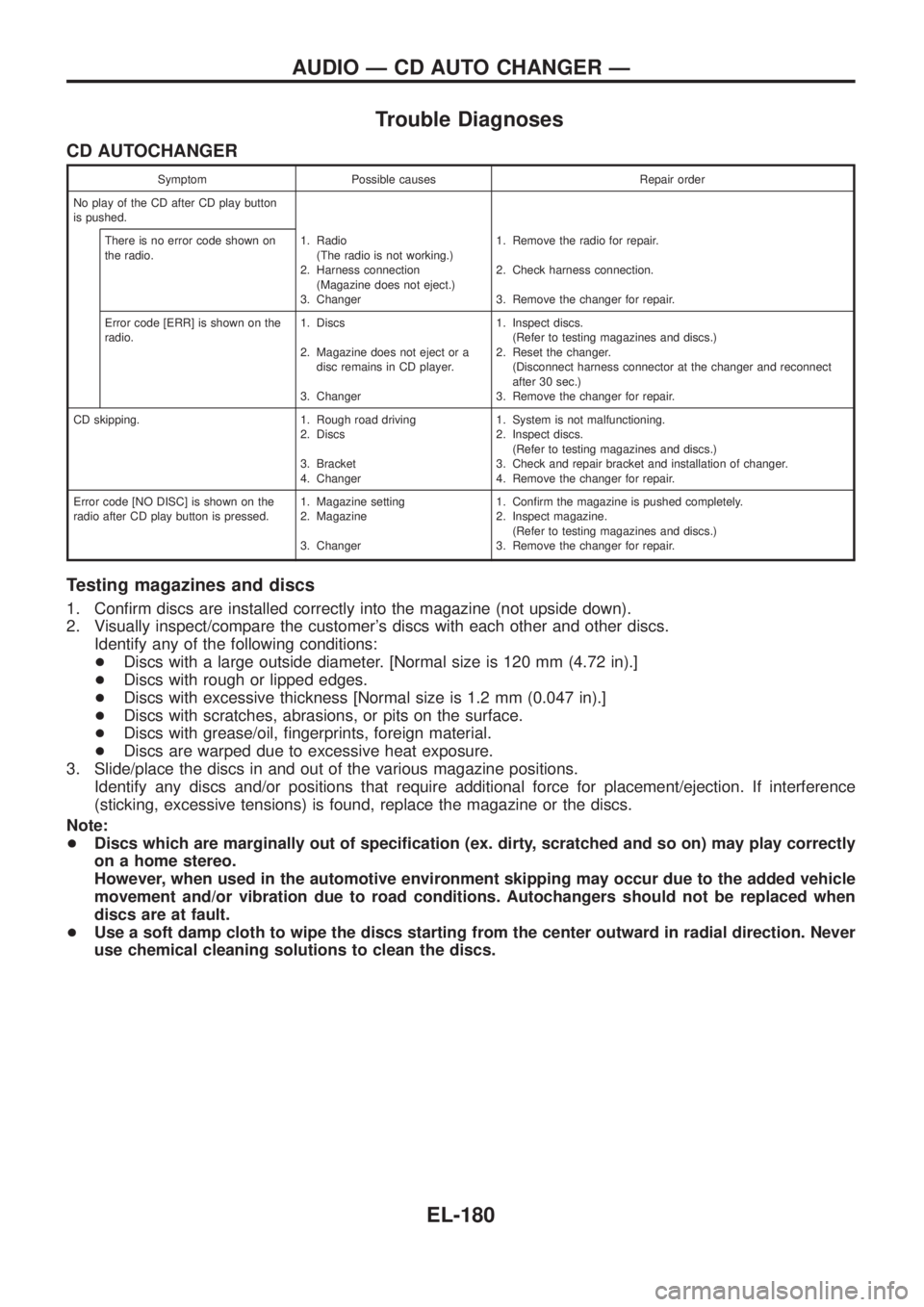
Trouble Diagnoses
CD AUTOCHANGER
Symptom Possible causes Repair order
No play of the CD after CD play button
is pushed.
There is no error code shown on
the radio.1. Radio
(The radio is not working.)
2. Harness connection
(Magazine does not eject.)
3. Changer1. Remove the radio for repair.
2. Check harness connection.
3. Remove the changer for repair.
Error code [ERR] is shown on the
radio.1. Discs
2. Magazine does not eject or a
disc remains in CD player.
3. Changer1. Inspect discs.
(Refer to testing magazines and discs.)
2. Reset the changer.
(Disconnect harness connector at the changer and reconnect
after 30 sec.)
3. Remove the changer for repair.
CD skipping. 1. Rough road driving
2. Discs
3. Bracket
4. Changer1. System is not malfunctioning.
2. Inspect discs.
(Refer to testing magazines and discs.)
3. Check and repair bracket and installation of changer.
4. Remove the changer for repair.
Error code [NO DISC] is shown on the
radio after CD play button is pressed.1. Magazine setting
2. Magazine
3. Changer1. Con®rm the magazine is pushed completely.
2. Inspect magazine.
(Refer to testing magazines and discs.)
3. Remove the changer for repair.
Testing magazines and discs
1. Con®rm discs are installed correctly into the magazine (not upside down).
2. Visually inspect/compare the customer's discs with each other and other discs.
Identify any of the following conditions:
+Discs with a large outside diameter. [Normal size is 120 mm (4.72 in).]
+Discs with rough or lipped edges.
+Discs with excessive thickness [Normal size is 1.2 mm (0.047 in).]
+Discs with scratches, abrasions, or pits on the surface.
+Discs with grease/oil, ®ngerprints, foreign material.
+Discs are warped due to excessive heat exposure.
3. Slide/place the discs in and out of the various magazine positions.
Identify any discs and/or positions that require additional force for placement/ejection. If interference
(sticking, excessive tensions) is found, replace the magazine or the discs.
Note:
+Discs which are marginally out of speci®cation (ex. dirty, scratched and so on) may play correctly
on a home stereo.
However, when used in the automotive environment skipping may occur due to the added vehicle
movement and/or vibration due to road conditions. Autochangers should not be replaced when
discs are at fault.
+Use a soft damp cloth to wipe the discs starting from the center outward in radial direction. Never
use chemical cleaning solutions to clean the discs.
AUDIO Ð CD AUTO CHANGER Ð
EL-180
Page 660 of 1226

Use the chart below to ®nd out what each wiring diagram code
stands for.
Code Section Wiring Diagram Name
A/C,A HA Auto Air Conditioner
A/C CUT EC Air Conditioner Cut Control
A/C,M HA Manual Air Conditioner
A/T AT A/T
AAC/V EC IACV-AAC Valve
ABS BR Anti-lock Brake System
ACC/SW EC Accelerator Switch (FC)
ACL/SW EC Accelerator Position Switch
ADJRES EC Adjustment Resistor
APS EC Accelerator Position Sensor
ASCD EL Automatic Speed Control Device
AT/C EC A/T Control
AUDIO EL Audio
BACK/L EL Back-up Lamp
BCDD EC BCDD System
CD/CHG EL CD Auto Changer
CHARGE EL Charging System
CHIME EL Warning Chime
CHOKE EC Automatic Choke
CIGAR EL Cigarette Lighter
CKPS EC Crankshaft Position Sensor (OBD)
CLOCK EL Clock
CMPS EC Camshaft Position Sensor
COMPAS EL Compass and Thermometer
COOL/B HA Cool Box
COOL/F EC Cooling Fan Control
CORNER EL Cornering Lamp
CSPS EC Control Sleeve Position Sensor
D/LOCK EL Power Door Lock
DEICER EL Wiper Deicer
DEF EL Rear Window Defogger
DIFF/L PD Differential Lock Control System
DTRL ELHeadlamp Ð With Daytime Light
System
ECTS EC Engine Coolant Temperature Sensor
EGRC/V EC EGRC-Solenoid Valve
F/FOG EL Front Fog Lamp
F/PUMP EC Fuel Pump
FCUT EC Fuel Cut Solenoid Valve
FICD EC IACV-FICD Solenoid Valve
FTS EC Fuel Temperature SensorCode Section Wiring Diagram Name
GLOW EC Quick Glow System
GOVNR EC Electric Governor
H/AIM EL Headlamp Aiming Control System
H/LAMP EL Headlamp
HEATUP EC Heat up Switch
HLC EL Headlamp Cleaner
HORN EL Horn
HSEAT EL Heated Seat
IATS EC Intake Air Temperature Sensor
IC/FAN EC Charge Air Cooler Fan
IGN EC Ignition System
IGN/SG EC Ignition Signal
ILL EL Illumination
INJECT EC Injector
INT/L EL Spot, Vanity Mirror Lamps
KS EC Knock Sensor
MAFS EC Mass Air Flow Sensor
MAIN ECMain Power Supply and Ground Cir-
cuit
METER ELSpeedometer, Tachometer, Temp.,
Oil and Fuel Gauges
MIL/DL EC Mil and Data Link Connectors
MIRROR EL Door Mirror
MULTI EL Multi-remote Control System
NATS EL Nissan Anti-Theft System
NLS EC Needle Lift Sensor
P/ANT EL Power Antenna
PLA EC Partial Load Advance Control
PNP/SW EC Park/Neutral Position Switch
POWER EL Power Supply Routing
PST/SW EC Power Steering Oil Pressure Switch
R/COOL HA Rear Cooler System
R/FOG EL Rear Fog Lamp
R/HEAT HA Rear Heater System
ROOM/L EL Interior Room Lamp
S/LOCK EL Power Door Lock Ð Super Lock
S/SIG EC Start Signal
S/TANK FE Sub Fuel Tank Control System
SEAT EL Power Seat
SROOF EL Sunroof
SRS RS Supplemental Restraint System
WIRING DIAGRAM CODES (CELL CODES)
EL-315
Page 668 of 1226

ENGINE MECHANICAL
SECTION
EM
CONTENTS
PRECAUTIONS...............................................................1
Parts Requiring Angular Tightening .............................1
Liquid Gasket Application Procedure ..........................1
PREPARATION................................................................2
NOISE, VIBRATION AND HARSHNESS (NVH)
TROUBLESHOOTING.....................................................6
NVH Troubleshooting Chart Ð Engine Noise .............7
OUTER COMPONENT PARTS.......................................8
COMPRESSION PRESSURE........................................10
Measurement of Compression Pressure ...................10
OIL PAN.........................................................................13
Removal .....................................................................13
Installation ..................................................................14
TIMING BELT.................................................................15
Removal .....................................................................15
Inspection...................................................................17
Installation ..................................................................18
OIL SEAL REPLACEMENT..........................................20
TURBOCHARGER.........................................................23
Removal and Installation ...........................................23
Inspection...................................................................24CHARGE AIR COOLERS..............................................27
CYLINDER HEAD..........................................................28
Removal .....................................................................29
Disassembly...............................................................30
Inspection...................................................................31
Assembly ...................................................................37
Installation ..................................................................37
VALVE CLEARANCE....................................................40
Checking ....................................................................40
Adjusting ....................................................................41
ENGINE REMOVAL.......................................................43
Removal .....................................................................44
Installation ..................................................................44
CYLINDER BLOCK.......................................................45
Disassembly...............................................................46
Inspection...................................................................46
Assembly ...................................................................53
SERVICE DATA AND SPECIFICATIONS (SDS)..........56
General Speci®cations ...............................................56
Inspection and Adjustment ........................................56
EM
Page 669 of 1226
Parts Requiring Angular Tightening
+Some important engine parts are tightened using an angular-
tightening method rather than a torque setting method.
+If these parts are tightened using a torque setting method, dis-
persal of the tightening force (axial bolt force) will be two or
three times that of the dispersal produced by using the correct
angular-tightening method.
+Although the torque setting values (described in this manual)
are equivalent to those used when bolts and nuts are tightened
with an angular-tightening method, they should be used for
reference only.
+To assure the satisfactory maintenance of the engine, bolts and
nuts must be tightened using an angular-tightening method.
+Before tightening the bolts and nuts, ensure that the thread and
seating surfaces are clean and then coated with engine oil.
+The bolts and nuts which require the angular-tightening method
are cylinder head bolts.
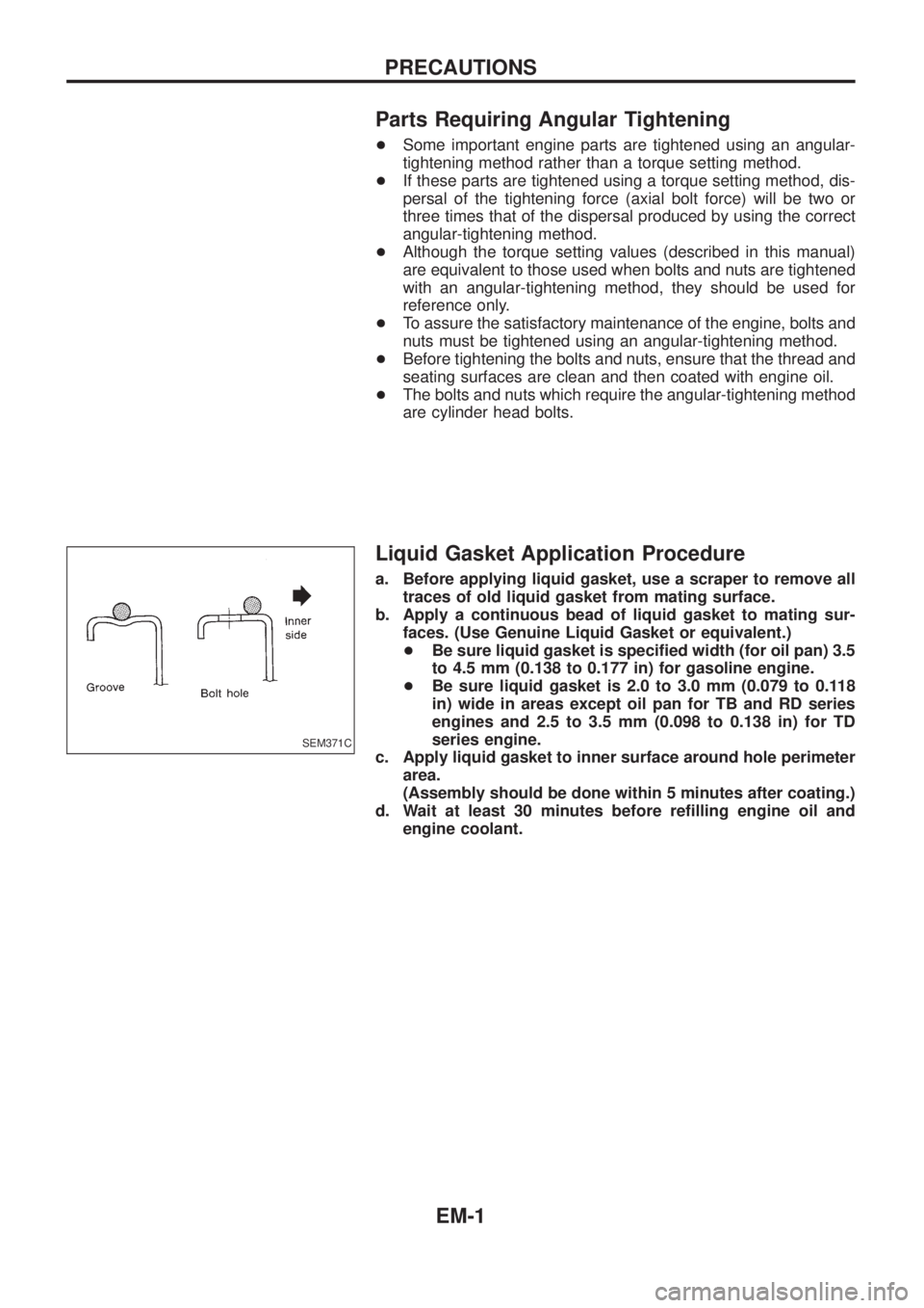
Liquid Gasket Application Procedure
a. Before applying liquid gasket, use a scraper to remove all
traces of old liquid gasket from mating surface.
b. Apply a continuous bead of liquid gasket to mating sur-
faces. (Use Genuine Liquid Gasket or equivalent.)
+Be sure liquid gasket is speci®ed width (for oil pan) 3.5
to 4.5 mm (0.138 to 0.177 in) for gasoline engine.
+Be sure liquid gasket is 2.0 to 3.0 mm (0.079 to 0.118
in) wide in areas except oil pan for TB and RD series
engines and 2.5 to 3.5 mm (0.098 to 0.138 in) for TD
series engine.
c. Apply liquid gasket to inner surface around hole perimeter
area.
(Assembly should be done within 5 minutes after coating.)
d. Wait at least 30 minutes before re®lling engine oil and
engine coolant.
SEM371C
PRECAUTIONS
EM-1
Page 670 of 1226
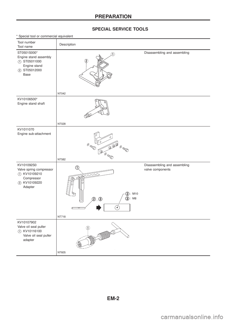
SPECIAL SERVICE TOOLS
* Special tool or commercial equivalent
Tool number
Tool nameDescription
ST0501S000*
Engine stand assembly
V1ST05011000
Engine stand
V2ST05012000
Base
NT042
Disassembling and assembling
KV10106500*
Engine stand shaft
NT028
KV1011070
Engine sub-attachment
NT582
KV101092S0
Valve spring compressor
V1KV10109210
Compressor
V2KV10109220
Adapter
NT718
Disassembling and assembling
valve components
KV10107902
Valve oil seal puller
V1KV10116100
Valve oil seal puller
adapter
NT605
PREPARATION
EM-2
Page 672 of 1226
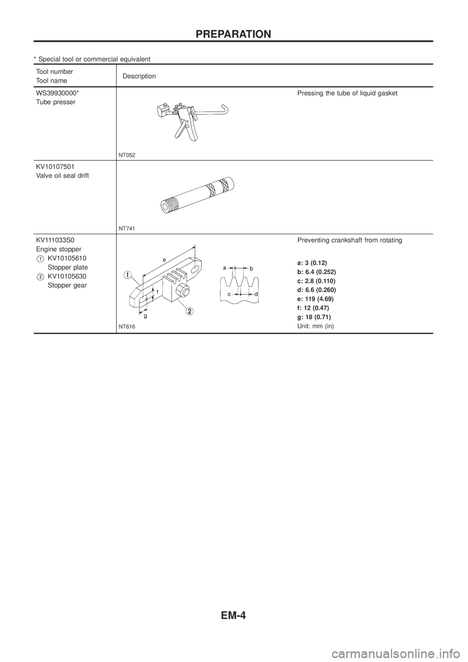
* Special tool or commercial equivalent
Tool number
Tool nameDescription
WS39930000*
Tube presser
NT052
Pressing the tube of liquid gasket
KV10107501
Valve oil seal drift
NT741
KV111033S0
Engine stopper
V1KV10105610
Stopper plate
V2KV10105630
Stopper gear
NT616
Preventing crankshaft from rotating
a: 3 (0.12)
b: 6.4 (0.252)
c: 2.8 (0.110)
d: 6.6 (0.260)
e: 119 (4.69)
f: 12 (0.47)
g: 18 (0.71)
Unit: mm (in)
PREPARATION
EM-4