Page 1042 of 1226

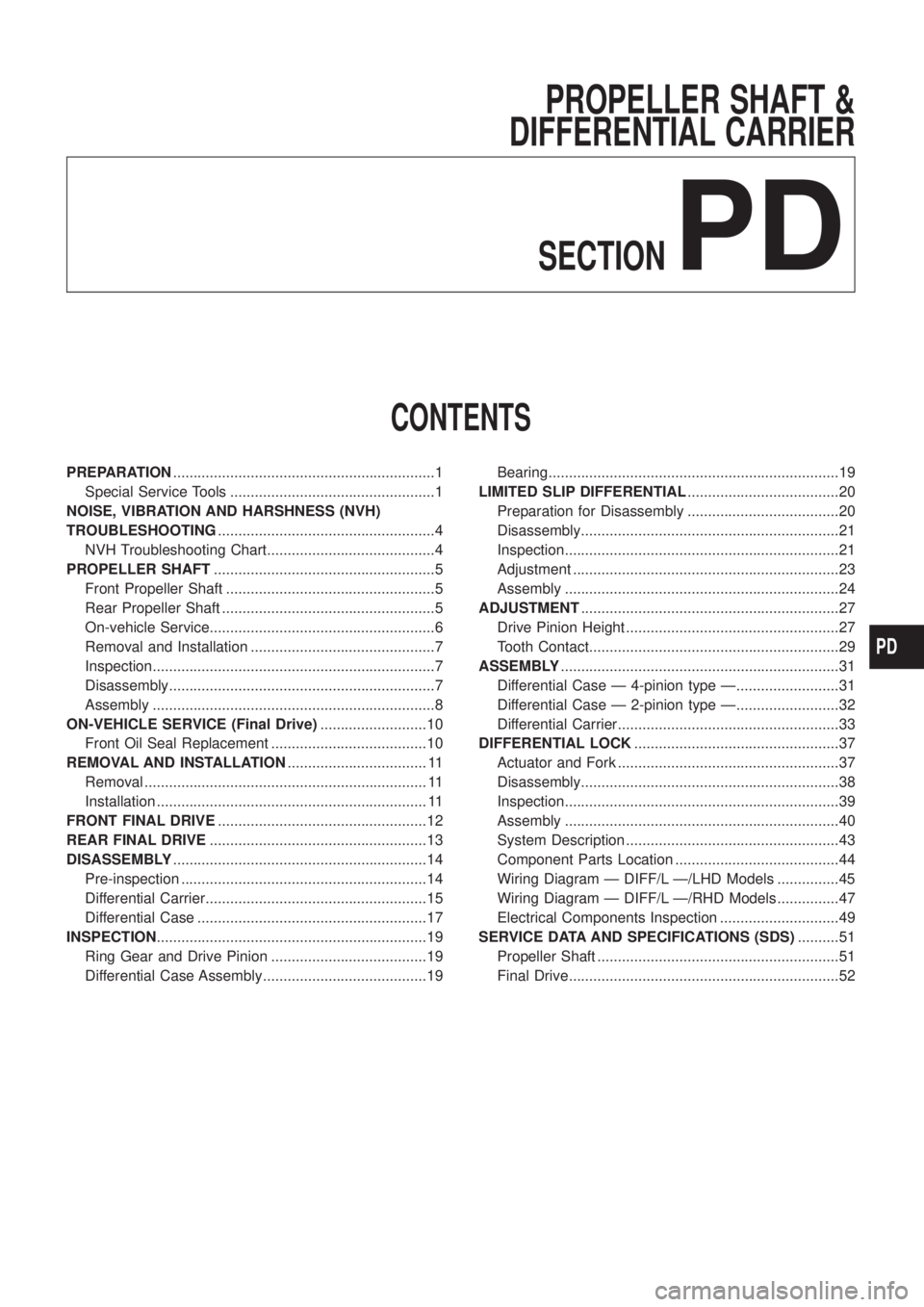
PROPELLER SHAFT &
DIFFERENTIAL CARRIER
SECTION
PD
CONTENTS
PREPARATION................................................................1
Special Service Tools ..................................................1
NOISE, VIBRATION AND HARSHNESS (NVH)
TROUBLESHOOTING.....................................................4
NVH Troubleshooting Chart.........................................4
PROPELLER SHAFT......................................................5
Front Propeller Shaft ...................................................5
Rear Propeller Shaft ....................................................5
On-vehicle Service.......................................................6
Removal and Installation .............................................7
Inspection.....................................................................7
Disassembly.................................................................7
Assembly .....................................................................8
ON-VEHICLE SERVICE (Final Drive)..........................10
Front Oil Seal Replacement ......................................10
REMOVAL AND INSTALLATION.................................. 11
Removal ..................................................................... 11
Installation .................................................................. 11
FRONT FINAL DRIVE...................................................12
REAR FINAL DRIVE.....................................................13
DISASSEMBLY..............................................................14
Pre-inspection ............................................................14
Differential Carrier......................................................15
Differential Case ........................................................17
INSPECTION..................................................................19
Ring Gear and Drive Pinion ......................................19
Differential Case Assembly........................................19Bearing.......................................................................19
LIMITED SLIP DIFFERENTIAL.....................................20
Preparation for Disassembly .....................................20
Disassembly...............................................................21
Inspection...................................................................21
Adjustment .................................................................23
Assembly ...................................................................24
ADJUSTMENT...............................................................27
Drive Pinion Height ....................................................27
Tooth Contact.............................................................29
ASSEMBLY....................................................................31
Differential Case Ð 4-pinion type Ð.........................31
Differential Case Ð 2-pinion type Ð.........................32
Differential Carrier......................................................33
DIFFERENTIAL LOCK..................................................37
Actuator and Fork ......................................................37
Disassembly...............................................................38
Inspection...................................................................39
Assembly ...................................................................40
System Description ....................................................43
Component Parts Location ........................................44
Wiring Diagram Ð DIFF/L Ð/LHD Models ...............45
Wiring Diagram Ð DIFF/L Ð/RHD Models ...............47
Electrical Components Inspection .............................49
SERVICE DATA AND SPECIFICATIONS (SDS)..........51
Propeller Shaft ...........................................................51
Final Drive..................................................................52
PD
Page 1045 of 1226
Tool number
Tool nameDescription Unit application
H233B
KV381025S0
Oil seal ®tting tool
V1ST30720000
Drift bar
V2KV38102510
Drift
NT525
Installing front oil seal
X
a: 77 mm (3.03 in) dia.
b: 55 mm (2.17 in) dia.
c: 71 mm (2.80 in) dia.
d: 65 mm (2.56 in) dia.
ST32580000
Differentialsidebearing
adjustingnutwrench
ST3125S001 Drive pinion setting gauge set 1 ST3131251000 Height Gauge 2 ST31181001
Dummy Shaft
3 KV38108700 Spacer [thickness: 2.00 mm (0.0787 in)]
NT141
Adjusting side bearing pre-
load and backlash (ring gear-
drive pinion)
X
X
PREPARATION
Special Service Tools (Cont'd)
PD-3
Page 1048 of 1226
On-vehicle Service
PROPELLER SHAFT VIBRATION
If vibration is present at high speed, inspect propeller shaft runout
®rst.
1. Raise front and rear wheels.
2. Measure propeller shaft runout at several points by rotating
®nal drive companion ¯ange with hands.
Runout limit: 0.6 mm (0.024 in)
3. If runout exceeds speci®cations, disconnect propeller shaft at
®nal drive companion ¯ange; then rotate companion ¯ange 180
degrees and reconnect propeller shaft.
4. Check runout again. If runout still exceeds speci®cations,
replace propeller shaft assembly.
5. Perform road tests.
APPEARANCE CHECKING
+Inspect propeller shaft tube surface for dents or cracks. If
damaged, replace propeller shaft assembly.
SPD458A
SPD728
SPD102
PROPELLER SHAFT
PD-6
Page 1052 of 1226
Front Oil Seal Replacement
1. Remove propeller shaft.
2. Loosen drive pinion nut.
Tool number:
KV40104000
3. Remove companion ¯ange.
4. Remove front oil seal.
5. Apply multi-purpose grease to cavity at sealing lips of oil seal.
Press front oil seal into carrier.
6. Install companion ¯ange and drive pinion nut.
7. Install propeller shaft.
Tool number: KV381025S0
PD237
SPD737
SPD738
SPD739
ON-VEHICLE SERVICE (Final Drive)
PD-10
Page 1053 of 1226
Removal
+Remove propeller shaft.
+Remove drive shaft. Refer to FA section (``FRONT AXLE Ð
Knuckle Flange'').
+Remove axle shaft.
Refer to RA section (``REAR AXLE'').
+Remove front and rear ®nal drive mounting bolts.
CAUTION:
+Be careful not to damage spline, sleeve yoke and front oil
seal when removing propeller shaft.
+Before removing the ®nal drive assembly or rear axle
assembly, disconnect the ABS sensor harness connector
from the assembly and move it away from the ®nal drive/
rear axle assembly area. Failure to do so may result in the
sensor wires being damaged and the sensor becoming
inoperative.
Installation
+Fill ®nal drive with recommended gear oil.
+Pay attention to the direction of gasket.
SPD103
SPD123
SPD767
REMOVAL AND INSTALLATION
PD-11
Page 1094 of 1226

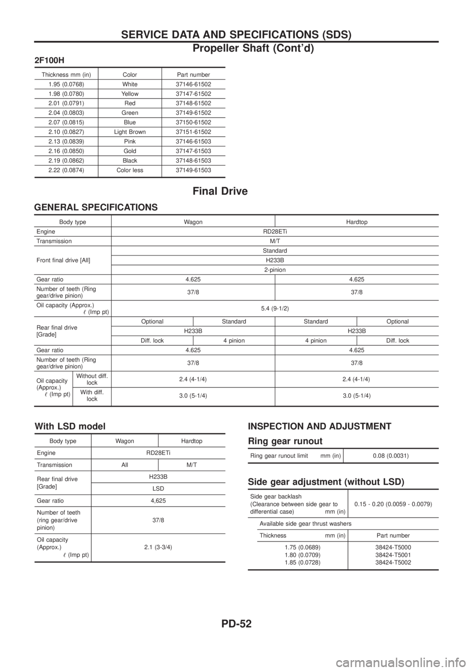
2F100H
Thickness mm (in) Color Part number1.95 (0.0768) White 37146-61502
1.98 (0.0780) Yellow 37147-61502
2.01 (0.0791) Red 37148-61502
2.04 (0.0803) Green 37149-61502
2.07 (0.0815) Blue 37150-61502
2.10 (0.0827) Light Brown 37151-61502
2.13 (0.0839) Pink 37146-61503
2.16 (0.0850) Gold 37147-61503
2.19 (0.0862) Black 37148-61503
2.22 (0.0874) Color less 37149-61503
Final Drive
GENERAL SPECIFICATIONS
Body type Wagon Hardtop
Engine RD28ETi
Transmission M/T
Front ®nal drive [All] Standard
H233B
2-pinion
Gear ratio 4.625 4.625
Number of teeth (Ring
gear/drive pinion) 37/8 37/8
Oil capacity (Approx.) !(Imp pt) 5.4 (9-1/2)
Rear ®nal drive
[Grade] Optional Standard Standard Optional
H233B H233B
Diff. lock 4 pinion 4 pinion Diff. lock
Gear ratio 4.625 4.625
Number of teeth (Ring
gear/drive pinion) 37/8 37/8
Oil capacity
(Approx.) !(Imp pt) Without diff.
lock 2.4 (4
-1/4)2.4 (4-1/4)
With diff.lock 3.0 (5-1/4) 3.0 (5-1/4)
With LSD model
Body type Wagon Hardtop
Engine RD28ETi
Transmission All M/T
Rear ®nal drive
[Grade] H233B
LSD
Gear ratio 4,625
Number of teeth
(ring gear/drive
pinion) 37/8
Oil capacity
(Approx.) !(Imp pt) 2.1 (3-3/4)
INSPECTION AND ADJUSTMENT
Ring gear runout
Ring gear runout limit mm (in) 0.08 (0.0031)
Side gear adjustment (without LSD)
Side gear backlash
(Clearance between side gear to
differential case) mm (in) 0.15 - 0.20 (0.0059 - 0.0079)
Available side gear thrust washers
Thickness mm (in) Part number 1.75 (0.0689)
1.80 (0.0709)
1.85 (0.0728) 38424-T5000
38424-T5001
38424-T5002
SERVICE DATA AND SPECIFICATIONS (SDS)
Propeller Shaft (Cont'd)
PD-52
Page 1186 of 1226
Inspection
PULLEY AND PULLEY SHAFT
+If pulley is cracked or deformed, replace it.
+If ¯uid leak is found around the pulley shaft, replace the oil seal.
Disassembly
CAUTION:
+Parts which can be disassembled are strictly limited. Never
disassemble parts other than those speci®ed.
+Disassemble in as clean a place as possible.
+Clean your hands before disassembly.
+Do not use rags; use nylon cloths or paper towels.
+When disassembling and reassembling, do not let foreign
matter enter or contact the parts.
+Remove snap ring, then draw drive shaft out.
+Be careful not to drop drive shaft.
+Remove oil seal.
+Be careful not to damage front housing.
+Remove connector.
+Be careful not to drop control valve.
SST010B
SST034A
SST036AA
POWER STEERING OIL PUMP
ST-17
Page 1193 of 1226

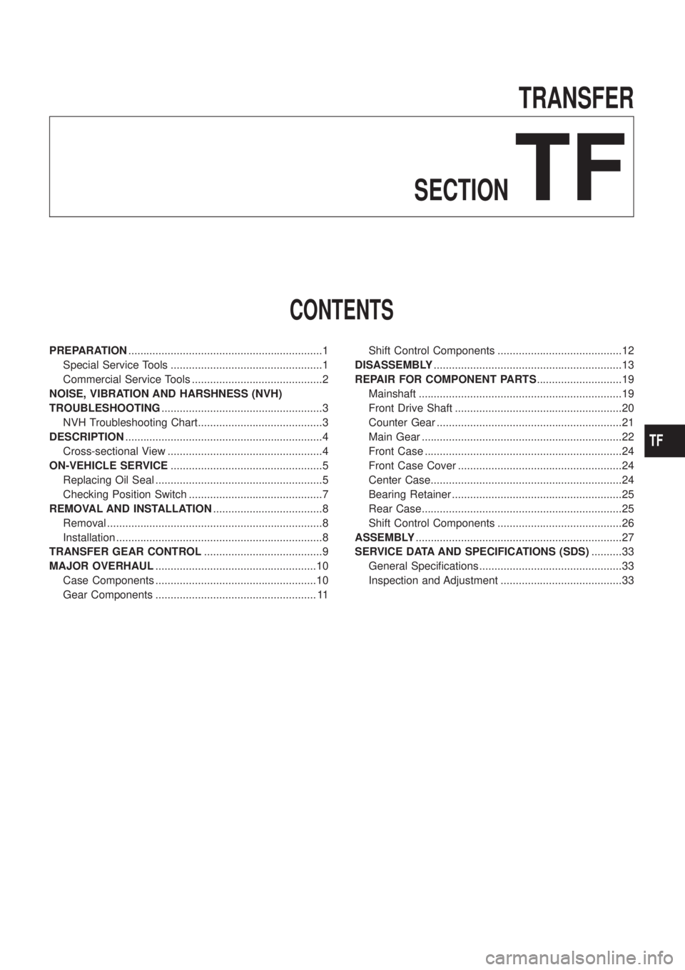
TRANSFER
SECTION
TF
CONTENTS
PREPARATION................................................................1
Special Service Tools ..................................................1
Commercial Service Tools ...........................................2
NOISE, VIBRATION AND HARSHNESS (NVH)
TROUBLESHOOTING.....................................................3
NVH Troubleshooting Chart.........................................3
DESCRIPTION.................................................................4
Cross-sectional View ...................................................4
ON-VEHICLE SERVICE..................................................5
Replacing Oil Seal .......................................................5
Checking Position Switch ............................................7
REMOVAL AND INSTALLATION....................................8
Removal .......................................................................8
Installation ....................................................................8
TRANSFER GEAR CONTROL.......................................9
MAJOR OVERHAUL.....................................................10
Case Components .....................................................10
Gear Components ..................................................... 11Shift Control Components .........................................12
DISASSEMBLY..............................................................13
REPAIR FOR COMPONENT PARTS............................19
Mainshaft ...................................................................19
Front Drive Shaft .......................................................20
Counter Gear .............................................................21
Main Gear ..................................................................22
Front Case .................................................................24
Front Case Cover ......................................................24
Center Case...............................................................24
Bearing Retainer ........................................................25
Rear Case..................................................................25
Shift Control Components .........................................26
ASSEMBLY....................................................................27
SERVICE DATA AND SPECIFICATIONS (SDS)..........33
General Speci®cations ...............................................33
Inspection and Adjustment ........................................33
TF