2006 NISSAN PATROL front drive shaft
[x] Cancel search: front drive shaftPage 756 of 1226
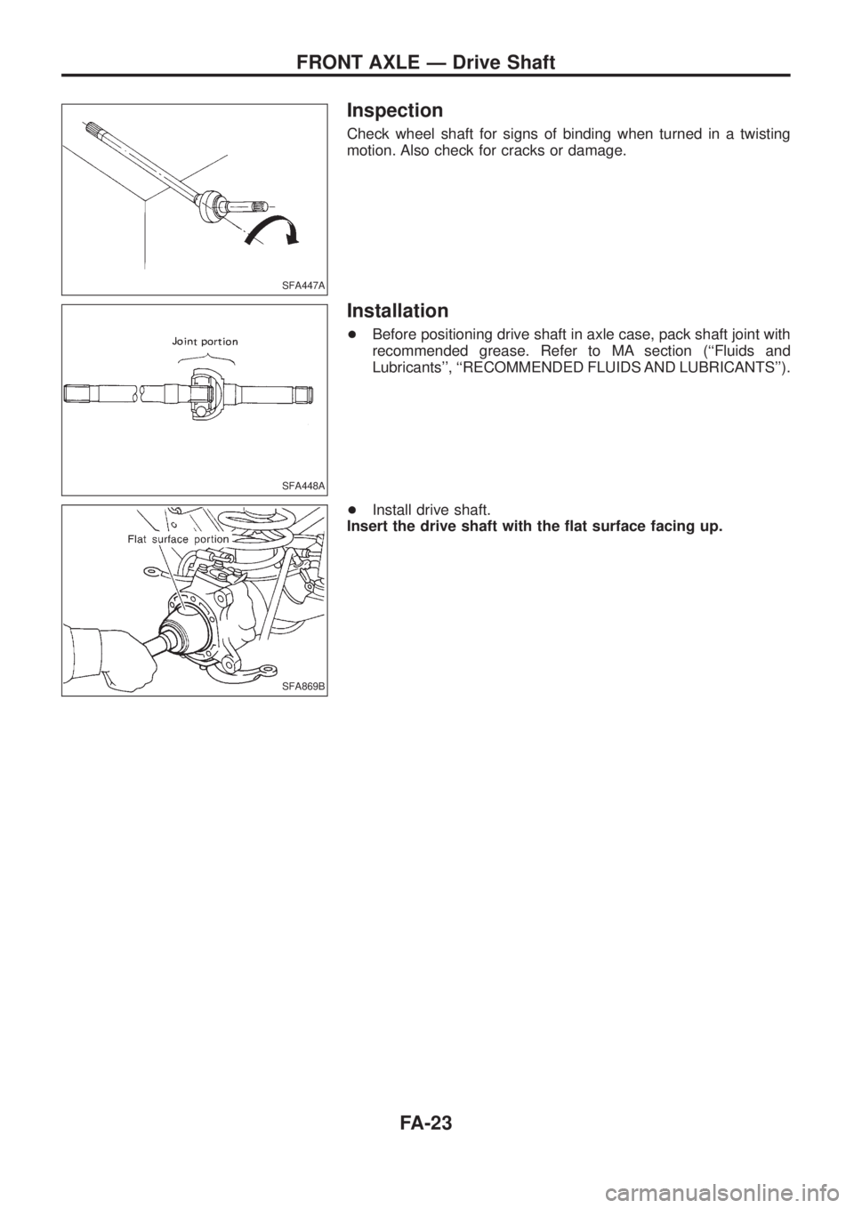
Inspection
Check wheel shaft for signs of binding when turned in a twisting
motion. Also check for cracks or damage.
Installation
+Before positioning drive shaft in axle case, pack shaft joint with
recommended grease. Refer to MA section (``Fluids and
Lubricants'', ``RECOMMENDED FLUIDS AND LUBRICANTS'').
+Install drive shaft.
Insert the drive shaft with the ¯at surface facing up.
SFA447A
SFA448A
SFA869B
FRONT AXLE Ð Drive Shaft
FA-23
Page 950 of 1226

Combination meter........................................EL-102
Combination switch .........................................EL-57
Combustion chamber replacement ................EM-32
Compass .......................................................EL-116
Compression pressure ...................................EM-10
Compressor special service tool ......................HA-6
Connecting rod...............................................EM-47
Connecting rod...............................................EM-51
Connector inspection .......................................GI-17
Console box - See Instrument panel ..............BT-11
Control lever (Transfer) .....................................TF-9
Control sleeve position sensor .......................EC-86
Coolant mixture ratio ......................................MA-11
Coolant replacement ......................................MA-14
Cooling circuit (engine) .....................................LC-9
Cooling fan control .......................................EC-112
Cooling fan motor .........................................EC-120
Cooling fan relay ..........................................EC-120
Cooling fan......................................................LC-15
Counter gear (M/T).........................................MT-10
Counter gear (Transfer) ..................................TF-11
Coupling sleeve (M/T) ....................................MT-10
Crankcase emission control system -
See Positive crankcase ventilation.............EC-21
Crankcase ventilation system - See
Positive crankcase ventilation ....................EC-21
Crankshaft position sensor (TDC)................EC-143
Crankshaft ......................................................EM-50
Cylinder block ..........................................EM-45, 48
Cylinder head .................................................EM-28
D
D/LOCK - Wiring diagram .............................EL-205
DEF - Wiring diagram ...................................EL-159
DEICER - Wiring diagram.............................EL-167
DTRL - Wiring diagram ...................................EL-67
Data link connector for Consult......................EC-36
Daytime light system.......................................EL-65
Diagnosis sensor unit .....................................RS-12
Diagnostic trouble code (DTC) for
ECCS OBD system ....................................EC-30
Differential carrier assembly...........................PD-31
Differential carrier disassembly ......................PD-14
Differential gear oil replacement ....................MA-22
Dimensions ......................................................GI-38
Dome light - See Interior lamp .......................EL-93
Door glass .........................................................BT-9
Door lock ...........................................................BT-9
Door mirror ......................................................BT-46
Door trim .........................................................BT-18
Door, front .........................................................BT-9
Door, rear ........................................................BT-10
Drive belt inspection ......................................MA-12
Drive chain (Transfer) .....................................TF-11
Drive pinion diff. inspection ............................PD-19
Drive pinion height .........................................PD-27
Drive shaft (front) ............................................FA-23
Dual pressure switch ......................................HA-11Dual pressure switch ......................................HA-97
E
ECCS basic inspection...................................EC-46
ECCS circuit diagram .....................................EC-11
ECCS component parts location ......................EC-8
ECCS on board diagnostic system ................EC-30
ECCS symptom matrix chart..........................EC-48
ECCS system diagram and chart ..................EC-12
ECCS-D control module .........................EC-54, 110
ECM input/output signal .................................EC-54
ECTS - Wiring diagram ..................................EC-78
EGR control (EGRC) - solenoid valve .........EC-155
EGR control valve ........................................EC-161
EGRC/V - Wiring diagram ............................EC-155
Electric governor ....................................EC-95, 148
Electric sunroof .............................................EL-186
Electrical diagnoses.........................................GI-20
Electrical unit.................................................EL-321
Electrical units location .................................EL-269
Electronic fuel injection pump ........................EC-27
Engine compartment .......................................BT-49
Engine coolant temperature sensor
(ECTS) ........................................................EC-78
Engine oil ®lter replacement ..........................MA-14
Engine oil precautions .......................................GI-4
Engine oil replacement ..................................MA-13
Engine outer component parts ........................EM-8
Engine removal ..............................................EM-43
Engine room - See Engine
compartment ...............................................BT-49
Engine serial number ......................................GI-37
Exhaust system inspection ............................MA-20
Exhaust system ................................................FE-3
Exterior ............................................................BT-26
F
FCUT - Wiring diagram ................................EC-129
FTS - Wiring diagram ...................................EC-134
Fan control amp. ............................................HA-88
Final drive disassembly ..................................PD-14
Final drive removal and installation................PD-11
Finisher, interior - See Trim ............................BT-14
Floor trim .........................................................BT-14
Flow charts ......................................................GI-30
Fluids................................................................MA-9
Flywheel (clutch).......................................CL-13, 14
Flywheel runout..............................................EM-52
Fog lamp, rear ................................................EL-80
Fork rod (M/T) ................................................MT-12
Front axle ........................................................FA-10
Front bumper ....................................................BT-4
Front case (Transfer) ......................................TF-10
Front disc brake .............................................BR-20
Front door .........................................................BT-9
ALPHABETICAL INDEX
IDX-3
Page 951 of 1226

Front drive shaft (Transfer) .............................TF-11
Front ®nal drive disassembly (4WD) ..............PD-14
Front ®nal drive removal and installa-
tion (4WD)...................................................PD-11
Front passenger air bag.............................RS-8, 14
Front seat belt ..................................................RS-2
Front seat ........................................................BT-32
Front suspension ............................................FA-24
Front washer .................................................EL-141
Front wiper ....................................................EL-141
Fuel cut control (at no load & high
engine speed) .............................................EC-20
Fuel cut solenoid valve ................................EC-129
Fuel ®ller lid.......................................................BT-6
Fuel ®lter replacement ...................................MA-16
Fuel gauge ....................................................EL-102
Fuel injection system......................................EC-15
Fuel line inspection ........................................MA-17
Fuel precautions ................................................GI-5
Fuel temperature sensor ..............................EC-134
Fuse block.....................................................EL-319
Fuse ................................................................EL-14
Fusible link ......................................................EL-14
G
GLOW - Wiring diagram...............................EC-150
GOVNR - Wiring diagram ..............................EC-95
Garage jack and safety stand .........................GI-39
Gauges..........................................................EL-102
Gear components (M/T) .................................MT-10
Glass .................................................................BT-9
Glow plug .............................................EC-150, 154
Glow relay ............................................EC-150, 154
Grease .............................................................MA-9
Ground distribution..........................................EL-15
H
H/AIM - Wiring diagram ..................................EL-71
H/LAMP - Wiring diagram ...............................EL-61
HEAT UP - Wiring diagram ..........................EC-182
HFC134a (R134a) system service
procedure ..................................................HA-112
HLC - Wiring diagram ...................................EL-153
HORN - Wiring diagram................................EL-155
Harness connector inspection .........................GI-17
Harness connector ............................................EL-2
Harness layout ..............................................EL-275
Headlamp aiming control ................................EL-70
Headlamp leveler - See Headlamp
aiming control ..............................................EL-70
Headlamp wiper ............................................EL-153
Headlamp ........................................................EL-61
Headlining - See Roof trim .............................BT-20
Heat up switch..............................................EC-182
Heated seat.....................................................BT-34Hood..................................................................BT-4
Horn ..............................................................EL-155
How to erase DTC for ECCS OBD
system ........................................................EC-30
I
IATS - Wiring diagram ..................................EC-121
IC/FAN - Wiring diagram ..............................EC-177
ILL - Wiring diagram .......................................EL-87
INT/L - Wiring diagram..................................EL-101
Identi®cation plate............................................GI-37
Idle speed inspection .....................................MA-19
Idle speed .......................................................EC-46
Illumination ......................................................EL-86
In vehicle sensor ..........................................HA-105
Injection nozzle inspection .............................MA-18
Injection nozzle...............................................EC-22
Injection timing control valve ........................EC-100
Instrument panel .............................................BT-11
Intake door control linkage adjustment ..........HA-84
Intake door motor ...........................................HA-25
Intake sensor ................................................HA-111
Interior lamp ....................................................EL-93
Interior .............................................................BT-14
J
Jacking points ..................................................GI-39
Joint connector (J/C).....................................EL-322
Journal bearing assembly (propeller
shaft) .............................................................PD-8
Journal bearing disassembly (propeller
shaft) .............................................................PD-7
Junction box (J/B) .........................................EL-319
L
LSV (Load sensing valve) ................................BR-6
Lifting points ....................................................GI-40
Limited slip diff. adjustment............................PD-23
Limited slip diff. assembly ..............................PD-24
Limited slip diff. disassembly .........................PD-21
Limited slip diff. inspection .............................PD-21
Location of electrical units ............................EL-269
Lock, door .........................................................BT-9
Lubricant (R134a) A/C ..................................HA-114
Lubricants.........................................................MA-9
Lubrication circuit (engine) ...............................LC-3
Lubrication-locks, hinges and hood
latches ........................................................MA-27
Luggage compartment trim .............................BT-14
Luggage room lamp ........................................EL-93
ALPHABETICAL INDEX
IDX-4
Page 952 of 1226
M
M/T major overhaul ..........................................MT-9
M/T removal and installation ............................MT-5
MAFS - Wiring diagram..................................EC-73
MAIN - Wiring diagram...................................EC-62
METER - Wiring diagram..............................EL-104
MIL & Data link connectors circuit ...............EC-187
MIL/DL - Wiring diagram ..............................EC-187
MIRROR - Wiring diagram............................EL-188
Main drive gear (M/T).....................................MT-10
Main gear (Transfer) .......................................TF-11
Mainshaft (M/T) ..............................................MT-10
Mainshaft (Transfer) ........................................TF-11
Maintenance (engine) ....................................MA-12
Major overhaul (Transfer) ...............................TF-10
Malfunction indicator lamp (MIL) ....................EC-31
Manifold tightening torque (intake &
exhaust)......................................................MA-12
Manual lock free running hub .........................FA-11
Manual transmission number ..........................GI-37
Mass air ¯ow sensor (MAFS).........................EC-73
Master cylinder (brake) ..................................BR-12
Meter .............................................................EL-102
Mirror, door......................................................BT-46
Mirror, outside .................................................BT-46
Mode door control linkage adjustment ...........HA-77
Model variation ................................................GI-35
Molding - See Exterior ....................................BT-26
Multiport fuel injection precautions ....................GI-3
N
NATS (Nissan Anti-theft System)..................EL-240
NATS - Wiring diagram .................................EL-241
NLS - Wiring diagram...................................EC-125
NVH Troubleshooting (PD)...............................PD-4
NVH troubleshooting (BR)................................BR-2
NVH troubleshooting (EM) ...............................EM-6
NVH troubleshooting (FA) .................................FA-3
NVH troubleshooting (MT) ...............................MT-3
NVH troubleshooting (RA)................................RA-3
NVH troubleshooting (RA)................................RA-3
NVH troubleshooting (ST).................................ST-3
NVH troubleshooting (Transfer) ........................TF-3
NVH troubleshooting CL ...................................CL-3
Needle lift sensor .........................................EC-125
Neutral position switch (M/T) ...........................MT-4
Neutral position switch .................................EC-169
O
Oil change (capacity) .......................................MA-9
Oil cooler (engine) ............................................LC-7
Oil jet.................................................................LC-7
Oil pan (engine) .............................................EM-13Oil pressure (engine) ........................................LC-3
Oil pump (engine) .............................................LC-4
Oil seal replacement (engine)........................EM-20
Oil seal replacement (front ®nal drive
4WD)...........................................................PD-10
Oil seal replacement (front of ®nal
drive) ...........................................................PD-10
Operating cylinder (clutch)................................CL-8
Outside mirror .................................................BT-46
P
P/ANT - Wiring diagram................................EL-181
PCV (positive crankcase ventilation) .............EC-21
PNP/SW - Wiring diagram ...........................EC-169
POWER - Wiring diagram.................................EL-6
Park/Neutral position switch .........................EC-169
Periodic maintenance (for Europe) ..................MA-4
Pinion bearing preload diff. ............................PD-27
Pinion gear height diff. ...................................PD-27
Piston assembly .............................................EM-46
Piston pin inspection ......................................EM-46
Piston ring inspection.....................................EM-47
Piston to bore clearance ................................EM-48
Power antenna ..............................................EL-181
Power door lock ............................................EL-204
Power door lock ............................................EL-211
Power door mirror .........................................EL-188
Power seat ....................................................EL-190
Power steering ¯uid level..................................ST-5
Power steering gear........................................ST-12
Power steering hydraulic pressure ...................ST-6
Power steering oil pump .................................ST-15
Power steering system bleeding.......................ST-6
Power supply routing ........................................EL-5
Power window ...............................................EL-196
Pre-delivery inspection.....................................MA-2
Precautions (General) .......................................GI-2
Pressure plate - See Clutch cover .................CL-14
Priming pump .................................................EC-46
Propeller shaft greasing .................................MA-21
Propeller shaft inspection ..............................MA-21
Propeller shaft on vehicle service ....................PD-6
Propeller shaft vibration ...................................PD-6
Propeller shaft ..................................................PD-5
Q
Quick-glow system check.............................EC-153
Quick-glow system .......................................EC-150
R
R/FOG - Wiring diagram .................................EL-80
R/HEAT - Wiring diagram ...............................HA-14
ALPHABETICAL INDEX
IDX-5
Page 953 of 1226
ROOM/L - Wiring diagram ..............................EL-95
Radiator ..........................................................LC-14
Radio - See Audio.........................................EL-168
Rear axle (disc brake type) ..............................RA-6
Rear bumper .....................................................BT-6
Rear case (Transfer) .......................................TF-10
Rear combination lamp removal and
installation ...................................................BT-26
Rear cover packing replacement diff..............PD-11
Rear disc brake ..............................................BR-24
Rear door ........................................................BT-10
Rear fog lamp .................................................EL-80
Rear heater - Wiring diagram ........................HA-14
Rear seat belt ...................................................RS-5
Rear seat ........................................................BT-35
Rear side window ...........................................BT-44
Rear suspension ............................................RA-12
Rear washer..................................................EL-145
Rear window defogger ..................................EL-158
Rear window ...................................................BT-42
Rear wiper.....................................................EL-145
Refrigerant connection precaution ...................HA-2
Refrigerant discharging evacuating
charging ....................................................HA-113
Refrigerant general precaution.........................HA-2
Refrigerant lines ...........................................HA-117
Refrigeration cycle ..........................................HA-11
Release bearing (clutch) .................................CL-11
Removal and installation (Transfer) ..................TF-8
Reverse idler shaft (M/T) ...............................MT-10
Reverse lamp switch (M/T) - See
Back-up lamp switch (M/T)...........................MT-4
Reverse main gear (M/T) ...............................MT-10
Ring gear diff. inspection ...............................PD-19
Road wheel size ..............................................GI-38
Roof trim .........................................................BT-20
Room lamp - See Interior lamp ......................EL-93
Rotor disc (front) .............................................FA-14
S
S/LOCK - Wiring diagram .............................EL-215
S/SIG - Wiring diagram ................................EC-162
SAE J1930 terminology list .............................GI-43
SEAT - Wiring diagram .................................EL-190
SMJ (super multiple junction) .......................EL-317
SROOF - Wiring diagram .............................EL-186
SRS - See Supplemental Restraint
System ..........................................................RS-8
SRS Trouble diagnoses .................................RS-22
STAB - Wiring diagram ..................................RA-18
START - Wiring diagram .................................EL-45
Screw jack .......................................................GI-39
Seal - See Exterior .........................................BT-26
Seat belt inspection .......................................MA-27
Seat belt pre-tensioner disposal ....................RS-17
Seat belt pre-tensioner ...................................RS-12
Seat belt, front ..................................................RS-2
Seat belt, rear...................................................RS-5Seat, front .......................................................BT-32
Seat, rear ........................................................BT-35
Seat, second (2nd) .........................................BT-35
Seat, third (3rd) ...............................................BT-37
Second (2nd) seat ..........................................BT-35
Self-diagnostic results ....................................EC-31
Shift control (Transfer) ....................................TF-12
Shift control components (M/T) ......................MT-12
Shift fork (M/T) ...............................................MT-12
Shift lever .......................................................MT-12
Shock absorber (front) ....................................FA-25
Shock absorber (rear) ....................................RA-14
Side bearing preload (front ®nal drive
4WD)...........................................................PD-27
Side bearing preload diff. ...............................PD-27
Side trim ..........................................................BT-14
Side window - See Rear side window ............BT-44
Speedometer.................................................EL-102
Spiral cable.....................................................RS-13
Stabilizer bar (front) ........................................FA-25
Stabilizer bar (rear) ........................................RA-15
Stabilizer release device - Wiring
diagram .......................................................RA-18
Stabilizer release device ................................RA-16
Standardized relay ............................................EL-3
Start signal ...................................................EC-162
Starter .............................................................EL-51
Starting system ...............................................EL-45
Steering gear and linkage inspection ............MA-26
Steering linkage ..............................................ST-19
Steering switch................................................EL-59
Steering wheel and column ..............................ST-8
Steering wheel play ..........................................ST-4
Steering wheel turning force .............................ST-6
Striking rod (M/T) ...........................................MT-12
Sub-gear (M/T) ...............................................MT-10
Sunload sensor ............................................HA-107
Sunroof, electric ............................................EL-186
Sunroof............................................................BT-39
Super lock .....................................................EL-211
Supplemental Restraint System .......................RS-8
Supplemental restraint system - Wiring
diagram .......................................................RS-27
Symbols and abbreviations ...............................GI-7
Synchronizer (M/T) .........................................MT-10
T
TCV - Wiring diagram ..................................EC-100
Tachometer ...................................................EL-102
Thermometer .................................................EL-116
Thermostat ......................................................LC-12
Third (3rd) seat ...............................................BT-37
Three way catalyst precautions.........................GI-4
Throttle control solenoid valve .....................EC-155
Throttle control solenoid valve .....................EC-161
Throwout bearing - See Clutch release
bearing ........................................................CL-11
Thrust washer selection diff. ..........................PD-27
ALPHABETICAL INDEX
IDX-6
Page 959 of 1226
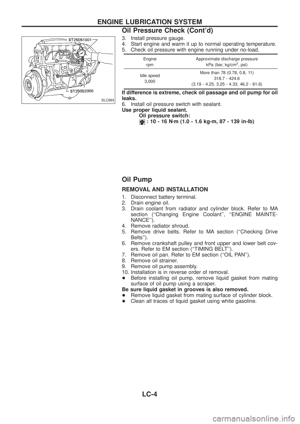
3. Install pressure gauge.
4. Start engine and warm it up to normal operating temperature.
5. Check oil pressure with engine running under no-load.
Engine
rpmApproximate discharge pressure
kPa (bar, kg/cm2, psi)
Idle speed
3,000More than 78 (0.78, 0.8, 11)
318.7 - 424.6
(3.19 - 4.25, 3.25 - 4.33, 46.2 - 61.6)
If difference is extreme, check oil passage and oil pump for oil
leaks.
6. Install oil pressure switch with sealant.
Use proper liquid sealant.
Oil pressure switch:
:10-16Nzm (1.0 - 1.6 kg-m, 87 - 139 in-lb)
Oil Pump
REMOVAL AND INSTALLATION
1. Disconnect battery terminal.
2. Drain engine oil.
3. Drain coolant from radiator and cylinder block. Refer to MA
section (``Changing Engine Coolant'', ``ENGINE MAINTE-
NANCE'').
4. Remove radiator shroud.
5. Remove drive belts. Refer to MA section (``Checking Drive
Belts'').
6. Remove crankshaft pulley and front upper and lower belt cov-
ers. Refer to EM section (``TIMING BELT'').
7. Remove oil pan. Refer to EM section (``OIL PAN'').
8. Remove oil strainer.
9. Remove oil pump assembly.
10. Installation is in reverse order of removal.
+Before installing oil pump, remove liquid gasket from mating
surface of oil pump using a scraper.
Be sure liquid gasket in grooves is also removed.
+Remove liquid gasket from mating surface of cylinder block.
+Clean all traces of liquid gasket using white gasoline.
SLC993
ENGINE LUBRICATION SYSTEM
Oil Pressure Check (Cont'd)
LC-4
Page 970 of 1226
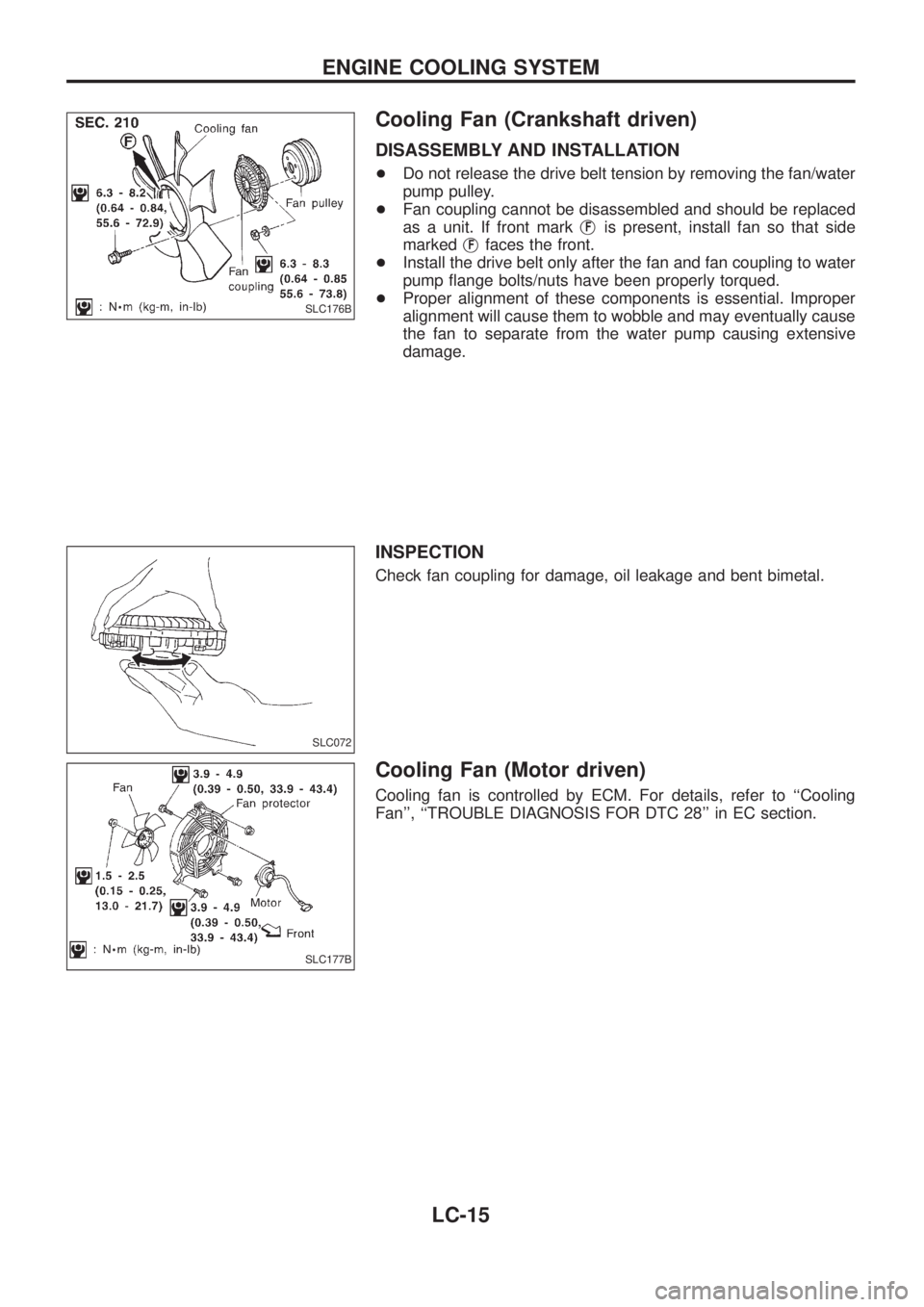
Cooling Fan (Crankshaft driven)
DISASSEMBLY AND INSTALLATION
+Do not release the drive belt tension by removing the fan/water
pump pulley.
+Fan coupling cannot be disassembled and should be replaced
as a unit. If front markj
Fis present, install fan so that side
markedj
Ffaces the front.
+Install the drive belt only after the fan and fan coupling to water
pump ¯ange bolts/nuts have been properly torqued.
+Proper alignment of these components is essential. Improper
alignment will cause them to wobble and may eventually cause
the fan to separate from the water pump causing extensive
damage.
INSPECTION
Check fan coupling for damage, oil leakage and bent bimetal.
Cooling Fan (Motor driven)
Cooling fan is controlled by ECM. For details, refer to ``Cooling
Fan'', ``TROUBLE DIAGNOSIS FOR DTC 28'' in EC section.
SLC176B
SLC072
SLC177B
ENGINE COOLING SYSTEM
LC-15
Page 977 of 1226
MAINTENANCE
SECTION
MA
CONTENTS
PRECAUTIONS AND PREPARATION............................1
Supplemental Restraint System (SRS) ``AIR
BAG'' and ``SEAT BELT PRE-TENSIONER''...............1
Special Service Tools ..................................................1
PRE-DELIVERY INSPECTION ITEMS............................2
GENERAL MAINTENANCE............................................3
PERIODIC MAINTENANCE............................................4
Engine Oil & Minor Service .........................................4
Engine and Emission Control Service .........................5
Chassis and Body Services.........................................6
Maintenance Under Severe Driving Conditions ..........8
RECOMMENDED FLUIDS AND LUBRICANTS.............9
Fluids and Lubricants ..................................................9
SAE Viscosity Number ..............................................10
Anti-freeze Coolant Mixture Ratio ............................. 11
ENGINE MAINTENANCE..............................................12
Checking Tightening Torque ......................................12
Checking Drive Belt ...................................................12
Changing Engine Oil..................................................13
Changing Engine Oil Filter ........................................14
Changing Engine Coolant..........................................14
Checking Cooling System .........................................16
Checking and Replacing Fuel Filter and Draining
Water .........................................................................16
Checking Fuel Lines ..................................................17
Cleaning and Replacing Air Cleaner Filter ................18
Checking Injection Nozzle .........................................18
Checking Idle Speed .................................................19
Timing Belt Replacement...........................................19
CHASSIS AND BODY MAINTENANCE.......................20
Checking Exhaust System.........................................20
Checking Clutch Fluid Level and Leaks ....................20
Checking Clutch System ...........................................20Checking M/T Oil Level and Leaks ...........................20
Changing M/T Oil.......................................................20
Checking Water Entry ................................................21
Checking Transfer Fluid Level ...................................21
Changing Transfer Fluid ............................................21
Checking Propeller Shaft ...........................................21
Greasing Nipples of Propeller Shafts ........................21
Checking Differential Gear Oil ...................................22
Changing Differential Gear Oil ..................................22
Checking Front Wheel Bearing Grease ....................22
Repacking Front Wheel Bearing and Axle Joint
Grease .......................................................................23
Checking Free-running Hub Grease .........................23
Checking Water Entry in Knuckle Flange..................23
Checking Brake Fluid Level and Leaks.....................23
Checking Brake System ............................................24
Changing Brake Fluid ................................................24
Checking Brake Booster, Vacuum Hoses,
Connections and Check Valve ..................................24
Checking Disc Brake .................................................24
Balancing Wheels ......................................................25
Tire Rotation ..............................................................25
Checking Power Steering Fluid and Lines ................26
Checking Steering Damper .......................................26
Checking Steering Gear Box and Linkage ................26
Lubricating Locks, Hinges and Hood Latches...........27
Checking Seat Belts, Buckles, Retractors,
Anchors and Adjusters...............................................27
Checking Body Corrosion ..........................................28
SERVICE DATA AND SPECIFICATIONS (SDS)..........29
Engine Maintenance ..................................................29
Chassis and Body Maintenance ................................29
MA