2006 MERCEDES-BENZ SPRINTER wheel torque
[x] Cancel search: wheel torquePage 1940 of 2305
WHEELS
DESCRIPTION
Original equipment wheels are designed for the
specified Maximum Vehicle Capacity.
All models use steel or aluminum wheels.
Aluminum wheels require special balance weights
and alignment equipment.
(1) On vehicles equipped with dual rear wheels,
The slots in the wheel must be aligned to provide
access to the valve stem.
OPERATION
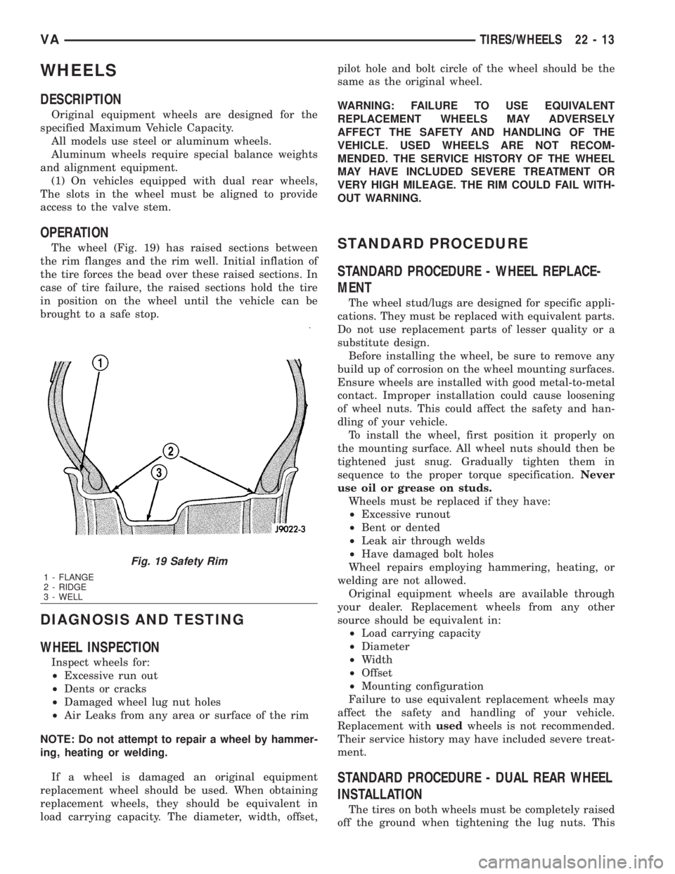
The wheel (Fig. 19) has raised sections between
the rim flanges and the rim well. Initial inflation of
the tire forces the bead over these raised sections. In
case of tire failure, the raised sections hold the tire
in position on the wheel until the vehicle can be
brought to a safe stop.
DIAGNOSIS AND TESTING
WHEEL INSPECTION
Inspect wheels for:
²Excessive run out
²Dents or cracks
²Damaged wheel lug nut holes
²Air Leaks from any area or surface of the rim
NOTE: Do not attempt to repair a wheel by hammer-
ing, heating or welding.
If a wheel is damaged an original equipment
replacement wheel should be used. When obtaining
replacement wheels, they should be equivalent in
load carrying capacity. The diameter, width, offset,pilot hole and bolt circle of the wheel should be the
same as the original wheel.
WARNING: FAILURE TO USE EQUIVALENT
REPLACEMENT WHEELS MAY ADVERSELY
AFFECT THE SAFETY AND HANDLING OF THE
VEHICLE. USED WHEELS ARE NOT RECOM-
MENDED. THE SERVICE HISTORY OF THE WHEEL
MAY HAVE INCLUDED SEVERE TREATMENT OR
VERY HIGH MILEAGE. THE RIM COULD FAIL WITH-
OUT WARNING.
STANDARD PROCEDURE
STANDARD PROCEDURE - WHEEL REPLACE-
MENT
The wheel stud/lugs are designed for specific appli-
cations. They must be replaced with equivalent parts.
Do not use replacement parts of lesser quality or a
substitute design.
Before installing the wheel, be sure to remove any
build up of corrosion on the wheel mounting surfaces.
Ensure wheels are installed with good metal-to-metal
contact. Improper installation could cause loosening
of wheel nuts. This could affect the safety and han-
dling of your vehicle.
To install the wheel, first position it properly on
the mounting surface. All wheel nuts should then be
tightened just snug. Gradually tighten them in
sequence to the proper torque specification.Never
use oil or grease on studs.
Wheels must be replaced if they have:
²Excessive runout
²Bent or dented
²Leak air through welds
²Have damaged bolt holes
Wheel repairs employing hammering, heating, or
welding are not allowed.
Original equipment wheels are available through
your dealer. Replacement wheels from any other
source should be equivalent in:
²Load carrying capacity
²Diameter
²Width
²Offset
²Mounting configuration
Failure to use equivalent replacement wheels may
affect the safety and handling of your vehicle.
Replacement withusedwheels is not recommended.
Their service history may have included severe treat-
ment.
STANDARD PROCEDURE - DUAL REAR WHEEL
INSTALLATION
The tires on both wheels must be completely raised
off the ground when tightening the lug nuts. This
Fig. 19 Safety Rim
1 - FLANGE
2 - RIDGE
3 - WELL
VATIRES/WHEELS 22 - 13
Page 1941 of 2305
will ensure correct wheel centering and maximum
wheel clamping.
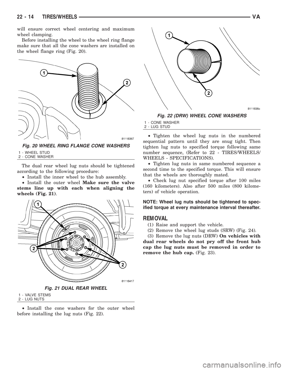
Before installing the wheel to the wheel ring flange
make sure that all the cone washers are installed on
the wheel flange ring (Fig. 20).
The dual rear wheel lug nuts should be tightened
according to the following procedure:
²Install the inner wheel to the hub assembly.
²Install the outer wheelMake sure the valve
stems line up with each when aligning the
wheels (Fig. 21).
²Install the cone washers for the outer wheel
before installing the lug nuts (Fig. 22).²Tighten the wheel lug nuts in the numbered
sequential pattern until they are snug tight. Then
tighten lug nuts to specified torque following same
number sequence, (Refer to 22 - TIRES/WHEELS/
WHEELS - SPECIFICATIONS).
²Tighten lug nuts in same numbered sequence a
second time to the specified torque. This will ensure
that the wheels are thoroughly mated.
²Check lug nut specified torque after 100 miles
(160 kilometers). Also after 500 miles (800 kilome-
ters) of vehicle operation.
NOTE: Wheel lug nuts should be tightened to spec-
ified torque at every maintenance interval thereafter.
REMOVAL
(1) Raise and support the vehicle.
(2) Remove the wheel lug studs (SRW) (Fig. 24).
(3) Remove the lug nuts (DRW)On vehicles with
dual rear wheels do not pry off the front hub
cap the lug nuts must be removed in order to
remove the hub cap.(Fig. 23).
Fig. 20 WHEEL RING FLANGE CONE WASHERS
1 - WHEEL STUD
2 - CONE WASHER
Fig. 21 DUAL REAR WHEEL
1 - VALVE STEMS
2 - LUG NUTS
Fig. 22 (DRW) WHEEL CONE WASHERS
1 - CONE WASHER
2 - LUG STUD
22 - 14 TIRES/WHEELSVA
Page 2046 of 2305
OPERATION
The compressor clutch components provide the
means to engage and disengage the compressor from
the engine serpentine accessory drive belt. When the
clutch coil is energized, it magnetically draws the
clutch into contact with the pulley and drives the
compressor shaft. When the coil is not energized, the
pulley freewheels on the clutch hub bearing, which is
part of the pulley.
The compressor clutch engagement is controlled by
several components:
²A/C switch on the A/C-heater control panel
²Evaporator temperature sensor
²A/C pressure transducer
²Air temperature sensor
²CAN bus messages
The compressor clutch is de-energized under any of
the following conditions:
²Blocked compressor (thermal fuse in the pulley)
²Low pressure in the system
²Low evaporator temperature
²Hard acceleration (WOT)
²High coolant temperatures
STANDARD PROCEDURE
A / C COMPRESSOR CLUTCH AIR GAP
If a new clutch plate and/or clutch pulley are being
used, the air gap between the clutch plate and clutch
pulley must be checked using the following proce-
dure:
(1) Using feeler gauges, measure the air gap
between the clutch plate and the clutch pulley fric-
tion surfaces.
(2) If the air gap is not between specifications
(Refer to 24 - HEATING & AIR CONDITIONING -
SPECIFICATIONS), add or subtract shims until the
desired air gap is obtained.
NOTE: The shims may compress after tightening
the compressor shaft bolt. Check the air gap in four
or more places on the clutch plate to verify that the
air gap is still correct. Spin the clutch pulley before
making the final air gap check.
A / C COMPRESSOR CLUTCH BREAK - IN
After a new compressor clutch has been installed,
cycle the compressor clutch approximately twenty
times (five seconds on, then five seconds off). During
this procedure, set the heater-A/C control in the
Recirculation Mode, the A/C button in the on posi-
tion, the blower motor switch in the highest speed
position, and the engine speed at 1500 to 2000 rpm.
This procedure (burnishing) will seat the opposing
friction surfaces and provide a higher compressor
clutch torque capability.
REMOVAL
The refrigerant system can remain fully-charged
during compressor clutch, pulley, or coil replacement.
The compressor clutch can be serviced in the vehicle.
(1) Disconnect and isolate the battery negative
cable.
(2) Remove the serpentine drive belt (Refer to 7 -
COOLING/ACCESSORY DRIVE/DRIVE BELTS -
REMOVAL).
(3) Disconnect the engine wire harness connector
for the compressor clutch coil from the clutch coil
wire harness connector on the top of the compressor.
(4) Remove the retainer securing the compressor
clutch coil lead on the top of the compressor.
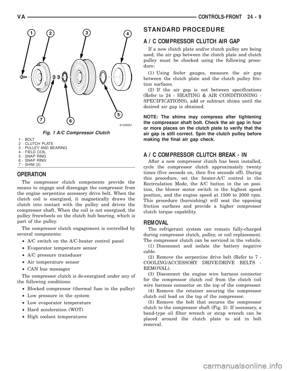
(5) Remove the bolt that secures the compressor
clutch to the compressor shaft (Fig. 2). If necessary, a
band-type oil filter wrench or strap wrench can be
placed around the clutch plate to aid in bolt
removal.
Fig. 1 A/C Compressor Clutch
1 - BOLT
2 - CLUTCH PLATE
3 - PULLEY AND BEARING
4 - FIELD COIL
5 - SNAP RING
6 - SNAP RING
7 - SHIM (2)
VACONTROLS-FRONT 24 - 9
Page 2159 of 2305
INSIDE HANDLE ACTUATOR......23-33, 23-36
INSTRUMENT CLUSTER................8J-2
INSTRUMENT PANEL ANTENNA CABLE....8A-2
INSTRUMENT PANEL ASSEMBLY........23-59
INSTRUMENT PANEL CENTER BEZEL.....23-57
INSTRUMENT PANEL DUCTS...........24-51
INTAKE AIR PRESSURE SENSOR........14-43
INTAKE AIR TEMPERATURE SENSOR.....14-42
INTAKE MANIFOLD....................9-65
INTERIOR..........................23-70
INTERMEDIATE SHAFT.................19-4
INTERNATIONAL SYMBOLS...............0-9
INTERNATIONAL SYMBOLS...........Intro.-2
INTRUSION SENSOR...................8Q-1
IN - CAR TEMPERATURE SENSOR.......24-21
JUMP STARTING.......................0-6
KEY / LOCK CYLINDER.................19-5
KNUCKLE.............................2-5
LAMPS / LIGHTING - EXTERIOR..........8L-2
LAMPS / LIGHTING - INTERIOR.........8L-28
LATCH RELEASE CABLE...............23-52
LATCH RELEASE HANDLE..............23-52
LATCH STRIKER.....................23-18
LATCH ..................23-18, 23-33, 23-52
LATCH / LOCK CONTROL...............23-38
LATERAL ACCELERATION SENSOR........5-33
LEFT MOUNT.........................9-55
LEVER..............................5-26
LICENSE PLATE BRACKET..............23-48
LICENSE PLATE LAMP BULB...........8L-19
LICENSE PLATE LAMP UNIT............8L-19
LINKAGE............................19-9
LIQUID LINE........................24-77
LOCK CYLINDER.....................23-18
LOW BEAM HEADLAMP BULB..........8L-20
LOW FUEL INDICATOR................8J-19
LOW OIL LEVEL INDICATOR............8J-20
LOWER BALL JOINT....................2-6
LOWER CONTROL ARM.................2-6
LOWER ROLLER ARM.................23-37
MAINTENANCE INDICATOR.............8J-20
MAINTENANCE SCHEDULES..............0-8
MALFUNCTION INDICATOR LAMP (MIL) . . . 8J-21
MANIFOLD AIR FLOW (MAF) SENSOR....14-44
MASTER CYLINDER...................5-17
MASTER LOCK SWITCH................8N-1
METRIC SYSTEM...................Intro.-6
MODE DOOR CABLES.................24-21
MULTI - FUNCTION INDICATOR..........8J-22
MULTI - FUNCTION SWITCH............8L-21
O2 SENSOR.........................14-45
ODOMETER.........................8J-22
OIL COOLER & LINES..................9-56
OIL FILTER ..........................9-57
OIL JET .............................9-57
OIL PAN .............................9-58
OIL PUMP...........................9-61
OIL PUMP.........................21-154
OIL SENSOR.........................9-64
OIL ................................9-56
OPENING DIMENSIONS................23-93
OUTPUT SHAFT BEARING.............21-156
OUTPUT SHAFT SEAL................21-159
PAINT TOUCH - UP...................23-77
PAINT.............................23-77
PARK BRAKE INDICATOR..............8J-23
PARK BRAKE SWITCH.................8L-21
PARK LOCK CABLE..................21-160
PARKING BRAKE......................5-23
PASSENGER AIRBAG BRACKET.........8O-27
PASSENGER AIRBAG.................8O-24
PASSENGER HEATED SEAT SWITCH.....8G-13
PEDAL..............................5-19
PISTON & CONNECTING ROD............9-45
PISTON RINGS.......................9-52
PISTONS..........................21-163
PLANETARY GEARTRAIN..............21-164
PLUMBING.........................24-61
POWER BRAKE BOOSTER...............5-19
POWER DISTRIBUTION CENTER.......8W-97-3
POWER DISTRIBUTION..............8W-97-1
POWER MIRROR SWITCH..............8N-3
POWER MIRRORS....................8N-3
POWER OUTLET
...................8W-97-3
POWER WINDOW SWITCH
..............8N-5
POWER WINDOWS
....................8N-5
PROP ROD
.........................23-53
PROPELLER SHAFT
.................3-1, 3-7PUMP.............................19-11
QUARTER TRIM PANEL................23-74
QUARTER WINDOW..................23-84
RADIATOR CROSSMEMBER............23-49
RADIATOR FAN.......................7-14
RADIATOR PRESSURE CAP..............7-19
RADIATOR...........................7-17
RADIO..............................8A-2
RAIN SENSOR CONTROL MODULE......8R-15
RAIN SENSOR.......................8R-12
REAR AXLE..........................3-12
REAR A / C CONDENSER FAN...........24-83
REAR A / C EVAPORATOR..............24-84
REAR A / C EXPANSION VALVE..........24-85
REAR BUMPER - STEP.................13-2
REAR CROSSMEMBER - TRANSMISSION . . 13-11
REAR DISCHARGE LINE...............24-88
REAR FASCIA........................13-3
REAR LATCH STRIKER................23-40
REAR LATCH........................23-40
REAR LIQUID LINE...................24-91
REAR RECEIVER / DRIER..............24-94
REAR REFRIGERANT RESERVOIR........24-95
REAR SEAT BACK SHIELD..............23-82
REAR SEAT BELT & RETRACTOR........8O-28
REAR SEAT BELT BUCKLE.............8O-30
REAR SIDE MARKER LAMP BULB.......8L-22
REAR SUCTION LINE..................24-96
REAR TURN LAMP BULB..............8L-23
REAR VIEW MIRROR.................23-75
REAR WHEEL SPEED SENSOR...........5-31
REAR WINDOW DEFOGGER GRID........8G-7
REAR WINDOW DEFOGGER RELAY.......8G-3
REAR WINDOW DEFOGGER SWITCH......8G-4
REAR...............................2-11
RECEIVER / DRIER...................24-79
RECIRCULATION DOOR ACTUATOR......24-22
REFRIGERANT LINE COUPLER..........24-98
REFRIGERANT OIL...................24-81
REFRIGERANT.......................24-80
RELAY...........................8W-97-4
REMOTE KEYLESS ENTRY
TRANSMITTER.......................8N-1
REPEATER LAMP BULB................8L-23
REPEATER LAMP UNIT................8L-24
RESTRAINTS.........................8O-2
RIGHT MOUNT.......................9-56
ROTORS............................5-20
SAFETY LATCH......................23-53
SEAL - PINION........................3-39
SEAT ADJUSTERS - FRONT.............23-81
SEAT BACK CUSHION / COVER - REAR....23-82
SEAT BACK - FRONT..................23-80
SEAT BELT SWITCH..................8O-31
SEAT BELT TENSIONER................8O-32
SEAT BELT TURNING LOOP ADJUSTER . . . 8O-33
SEAT CUSHION - FRONT...............23-80
SEAT CUSHION / COVER - REAR.........23-83
SEATBELT INDICATOR.................8J-24
SEAT - FRONT.......................23-79
SEAT - REAR........................23-81
SECURITY SYSTEM MODULE............8Q-2
SENTRY KEY REMOTE ENTRY MODULE....8Q-2
SERVO..............................8P-2
SHAFT - AXLE DUAL REAR WHEELS......3-27
SHAFT - AXLE SINGLE REAR WHEEL......3-23
SHIFT MECHANISM..................21-168
SHOCK..............................2-13
SHOES..............................5-27
SIDE CURTAIN AIRBAG................8O-35
SIDE IMPACT SENSOR................8O-39
SIDE VIEW MIRROR..................23-49
SIDE VIEW MIRROR - GLASS...........23-50
SIREN..............................8Q-4
SLIDING DOOR......................23-40
SOLENOID.........................21-171
SPARE TIRE CARRIER.................22-12
SPEAKER............................8A-2
SPEED CONTROL.....................8P-1
SPEEDOMETER......................8J-25
SPRING CLAMP PLATES.................2-8
SPRING SHACKLE.....................2-15
SPRING STOP PLATES..................2-9
SPRING
.........................2-7, 2-14
STABILIZER BAR
..................2-9, 2-15
STABILIZER LINK
.................2-10, 2-16
STABILIZER
.........................23-45
STARTER MOTOR RELAY
..............8F-35STARTER MOTOR....................8F-33
STARTING SYSTEM...................8F-28
STEERING ANGLE SENSOR..............5-32
STEERING COLUMN OPENING COVER....23-68
STEERING WHEEL.....................19-6
STEERING...........................19-1
STEPWELL SCUFF PADS...............23-75
STRUT..............................2-10
SUCTION LINE.......................24-81
SUN VISOR.........................23-76
SUPPORT PLATE......................5-23
SUPPRESSOR FILTER - REAR BLOWER
MOTOR............................24-41
SUPPRESSOR FILTER - REAR
CONDENSER FAN....................24-43
SWITCH.............................8P-3
TACHOMETER.......................8J-25
TAIL LAMP UNIT.....................8L-25
TAILPIPE............................11-3
TEMPERATURE CONTROL..............24-38
TEMPERATURE SENSOR...............24-40
TEMPERATURE SENSOR / PARK -
NEUTRAL CONTACT..................21-176
TERMINAL........................Intro.-10
THREADED HOLE REPAIR.............Intro.-6
TIE ROD END ........................19-10
TIME DELAY RELAY....................8L-35
TIMING CHAIN AND SPROCKETS.........9-72
TIMING CHAIN COVER.................9-70
TIMING CHAIN TENSIONER..............9-81
TIRES..............................22-7
TIRES / WHEELS......................22-1
TONE WHEEL........................5-32
TOP COVER.........................23-67
TOP COVER - CLUSTER................23-64
TOP COVER - TRAY...................23-65
TORQUE CONVERTER HUB SEAL.......21-184
TORQUE CONVERTER................21-178
TORQUE REFERENCES...............Intro.-9
TOWING.............................0-7
TRACTION CONTROL INDICATOR........8J-26
TRACTION CONTROL MALFUNCTION
INDICATOR.........................8J-27
TRAILER HITCH......................13-11
TRANSMISSION CONTROL MODULE......8E-6
TRANSPONDER KEY...................8Q-5
TRIM PANEL.............23-18, 23-34, 23-46
TURBOCHARGER SYSTEM..............11-3
TURBOCHARGER......................11-6
TURN SIGNAL INDICATOR..............8J-27
TURN SIGNAL RELAY.................8L-26
UNDERBODY LINES..................24-100
UPPER ROLLER ARM.................23-36
VACUUM PUMP.......................9-54
VALVE COOLER.......................25-6
VALVE SPRINGS......................9-35
VALVE STEM SEALS...................9-34
VALVE ..............................25-5
VEHICLE IDENTIFICATION NUMBER.....Intro.-1
VEHICLE THEFT SECURITY..............8Q-1
VIBRATION DAMPER...................9-53
VOLTAGE REGULATOR.................8F-24
WAIT - TO - START INDICATOR..........8J-28
WASHER FLUID INDICATOR............8J-29
WASHER FLUID LEVEL SWITCH.........8R-16
WASHER HOSES / TUBES..............8R-18
WASHER NOZZLE....................8R-18
WASHER PUMP / MOTOR..............8R-19
WASHER RESERVOIR.................8R-21
WATER IN FUEL SENSOR..............14-30
WATER PUMP........................7-20
WATER VALVE .......................24-83
WATER - IN - FUEL INDICATOR..........8J-29
WHEEL ALIGNMENT...................2-17
WHEELS...........................22-13
WINDOW MOTOR.....................8N-5
WINDOW REGULATOR - MANUAL........23-21
WINDOW REGULATOR - POWER........23-20
WINDSHIELD........................23-85
WIPER ARM........................8R-23
WIPER BLADE.......................8R-26
WIPER LINKAGE.....................8R-28
WIPER MOTOR......................8R-31
WIPER RELAY.......................8R-34
WIPERS/WASHERS....................8R-2
WIRING DIAGRAM INFORMATION......Intro.-1
YAW RATE SENSOR...................5-35
2 INDEXVA
Description Group-Page Description Group-Page Description Group-Page
Page 2163 of 2305
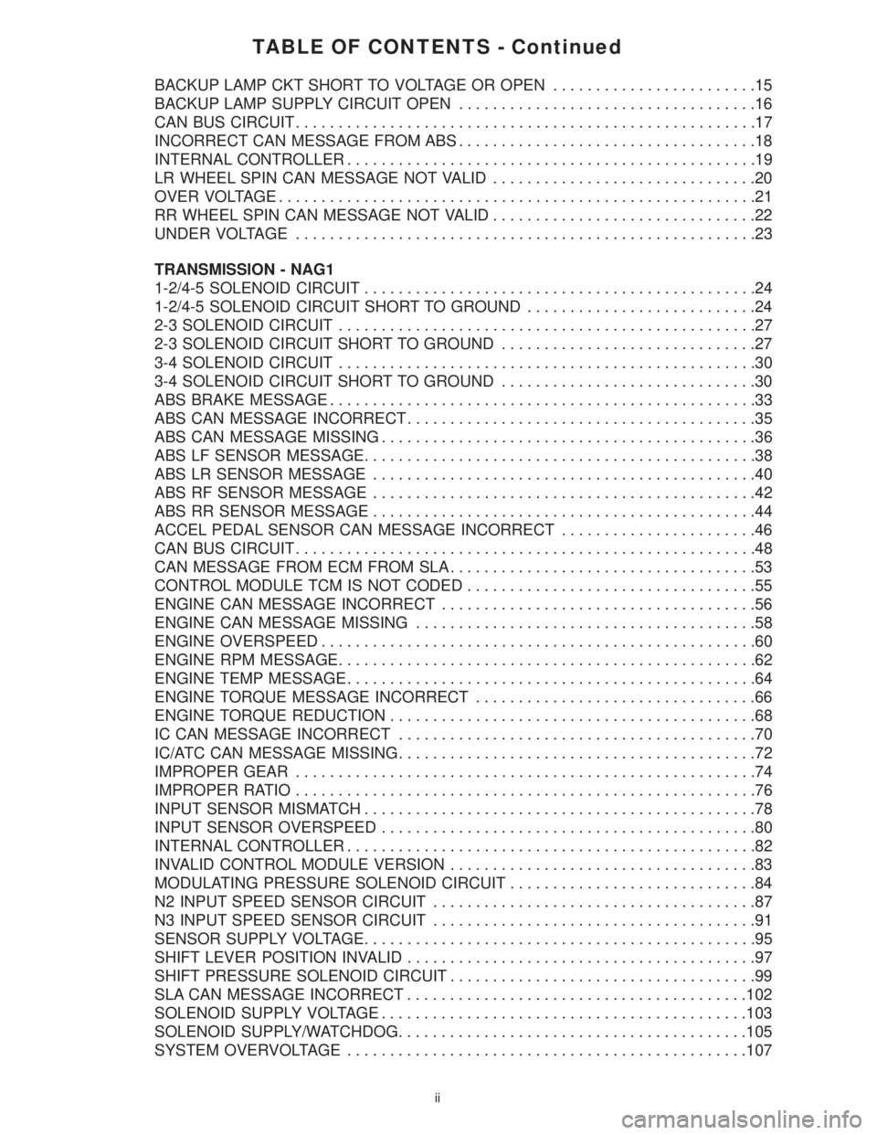
TABLE OF CONTENTS - Continued
BACKUP LAMP CKT SHORT TO VOLTAGE OR OPEN........................15
BACKUP LAMP SUPPLY CIRCUIT OPEN...................................16
CAN BUS CIRCUIT......................................................17
INCORRECT CAN MESSAGE FROM ABS...................................18
INTERNAL CONTROLLER................................................19
LR WHEEL SPIN CAN MESSAGE NOT VALID...............................20
OVER VOLTAGE........................................................21
RR WHEEL SPIN CAN MESSAGE NOT VALID...............................22
UNDER VOLTAGE......................................................23
TRANSMISSION - NAG1
1-2/4-5 SOLENOID CIRCUIT..............................................24
1-2/4-5 SOLENOID CIRCUIT SHORT TO GROUND...........................24
2-3 SOLENOID CIRCUIT.................................................27
2-3 SOLENOID CIRCUIT SHORT TO GROUND..............................27
3-4 SOLENOID CIRCUIT.................................................30
3-4 SOLENOID CIRCUIT SHORT TO GROUND..............................30
ABS BRAKE MESSAGE..................................................33
ABS CAN MESSAGE INCORRECT.........................................35
ABS CAN MESSAGE MISSING............................................36
ABS LF SENSOR MESSAGE..............................................38
ABS LR SENSOR MESSAGE.............................................40
ABS RF SENSOR MESSAGE.............................................42
ABS RR SENSOR MESSAGE.............................................44
ACCEL PEDAL SENSOR CAN MESSAGE INCORRECT.......................46
CAN BUS CIRCUIT......................................................48
CAN MESSAGE FROM ECM FROM SLA....................................53
CONTROL MODULE TCM IS NOT CODED..................................55
ENGINE CAN MESSAGE INCORRECT.....................................56
ENGINE CAN MESSAGE MISSING........................................58
ENGINE OVERSPEED...................................................60
ENGINE RPM MESSAGE.................................................62
ENGINE TEMP MESSAGE................................................64
ENGINE TORQUE MESSAGE INCORRECT.................................66
ENGINE TORQUE REDUCTION...........................................68
IC CAN MESSAGE INCORRECT..........................................70
IC/ATC CAN MESSAGE MISSING..........................................72
IMPROPER GEAR......................................................74
IMPROPER RATIO......................................................76
INPUT SENSOR MISMATCH..............................................78
INPUT SENSOR OVERSPEED............................................80
INTERNAL CONTROLLER................................................82
INVALID CONTROL MODULE VERSION....................................83
MODULATING PRESSURE SOLENOID CIRCUIT.............................84
N2 INPUT SPEED SENSOR CIRCUIT......................................87
N3 INPUT SPEED SENSOR CIRCUIT......................................91
SENSOR SUPPLY VOLTAGE..............................................95
SHIFT LEVER POSITION INVALID.........................................97
SHIFT PRESSURE SOLENOID CIRCUIT....................................99
SLA CAN MESSAGE INCORRECT........................................102
SOLENOID SUPPLY VOLTAGE...........................................103
SOLENOID SUPPLY/WATCHDOG.........................................105
SYSTEM OVERVOLTAGE...............................................107
ii
Page 2168 of 2305
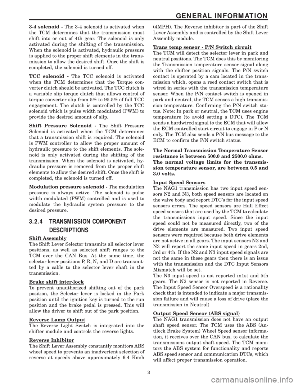
3-4 solenoid -The 3-4 solenoid is activated when
the TCM determines that the transmission must
shift into or out of 4th gear. The solenoid is only
activated during the shifting of the transmission.
When the solenoid is activated, hydraulic pressure
is applied to the proper shift elements in the trans-
mission to allow the desired shift. Once the shift is
completed, the solenoid is turned off.
TCC solenoid -The TCC solenoid is activated
when the TCM determines that the Torque con-
verter clutch should be activated. The TCC clutch is
a variable slip torque clutch that allows control of
torque converter slip from 5% to 95.5% of full TCC
engagement. The clutch is controlled by the TCC
solenoid which is pulse width modulated (PWM) to
provide the desired amount of slip.
Shift Pressure Solenoid -The Shift Pressure
Solenoid is activated when the TCM determines
that a transmission shift is required. The solenoid
is PWM controller to allow the proper amount of
hydraulic pressure to the shift elements. The sole-
noid is only activated during the shifting of the
transmission. When the solenoid is activated, hy-
draulic pressure is removed from the proper shift
elements to allow the desired shift. Once the shift is
completed, the solenoid is turned off.
Modulation pressure solenoid -The modulation
pressure is always active. The solenoid is pulse
width modulated (PWM) controlled and is used to
modulate the hydraulic system pressure to the
desired pressure.
3.2.4 TRANSMISSION COMPONENT
DESCRIPTIONS
Shift Assembly
The Shift Lever Selector transmits all selector lever
positions, as well as selected shift ranges to the
TCM over the CAN Bus. At the same time, the
selector lever positions P, R, N, and D are transmit-
ted by a cable to the selector lever shaft in the
transmission.
Brake shift inter-lock
To prevent unauthorized shifting out of the park
position, the Selector lever is locked in the Park
position until the ignition key is turned to the run
position and the brake pedal is pressed. This will
allow the driver to shift out of the park position.
Reverse Lamp Output
The Reverse Light Switch is integrated into the
shifter module and controls the reverse lights.
Reverse Inhibitor
The Shift Lever Assembly constantly monitors ABS
wheel speed to prevents an inadvertent selection of
reverse at speeds above approximately 6.4 Km/h(4MPH). The Reverse inhibitor is part of the Shift
Lever Assembly and is controlled by the Shift Lever
Assembly module.
Trans temp sensor - P/N Switch circuit
The TCM will detect the selector lever in park and
neutral positions. The TCM does this by monitoring
the Transmission temperature sensor signal along
with the shifter position signals. The P/N switch
contact is operated by a cam located in the trans-
mission which, opens a reed contact switch that is
wired in series with the transmission temperature
sensor. When the P/N contact switch is opened in
park and neutral, the TCM senses a high transmis-
sion temperature. Confirming the P/N switch sta-
tus. Note: In park or neutral, the TCM uses engine
temperature (to avoid setting a DTC). The TCM
sends a hardwired signal to the ECM that will allow
the ECM controlled start circuit to engage in P or N
only. The TCM also sends a P/N bus message to the
ECM to confirm the P/N switch status.
The Normal Transmission Temperature Sensor
resistance is between 500.0 and 2500.0 ohms.
The normal voltage limits for the transmis-
sion temperature sensor, are between 0.5 and
3.0 volts.
Input Speed Sensors
The NAG1 transmission has two input speed sen-
sors N2 and N3, both speed sensors are located on
the valve body and report DTC's for the input speed
sensors errors. The speed sensors are Hall Effect
speed sensors that are used by the TCM to calculate
the transmissions input speed. Since the input
speed could not be measured directly, two of the
drive elements are measured. Two input speed
sensors were required because both drive elements
are not active in all gears. The input sensors N2 and
N3 will report the same input speed in gears 2nd,
3rd or 4th. If the N2 and N3 input speed signals are
not the same in these gears then there is an issue
with the transmission and the DTC Input Sensors
Mismatch will be set.
The N3 input speed is not reported in1st and 5th
gears. The N2 sensor is not reported in Reverse.
The Input Speed Sensor Overspeed is a rationality
check that is intended to indicate a major transmis-
sion failure and will cause a loss of drive (place the
transmission in Neutral)
Output Speed Sensor (ABS signal)
The NAG1 transmission does not have an output
shaft speed sensor. The TCM uses the ABS (An-
tilock Brake System) Wheel Speed sensor informa-
tion, it receives over the CAN bus, to calculate the
transmissions output shaft speed. The TCM moni-
tors the ABS system for functionality and reports
ABS speed sensor and communication DTCs, which
will affect proper transmission operation.
3
GENERAL INFORMATION