2006 MERCEDES-BENZ SPRINTER wheel torque
[x] Cancel search: wheel torquePage 1908 of 2305
OPERATION
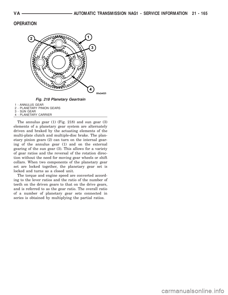
The annulus gear (1) (Fig. 218) and sun gear (3)
elements of a planetary gear system are alternately
driven and braked by the actuating elements of the
multi-plate clutch and multiple-disc brake. The plan-
etary pinion gears (2) can turn on the internal gear-
ing of the annulus gear (1) and on the external
gearing of the sun gear (3). This allows for a variety
of gear ratios and the reversal of the rotation direc-
tion without the need for moving gear wheels or shift
collars. When two components of the planetary gear
set are locked together, the planetary gear set is
locked and turns as a closed unit.
The torque and engine speed are converted accord-
ing to the lever ratios and the ratio of the number of
teeth on the driven gears to that on the drive gears,
and is referred to as the gear ratio. The overall ratio
of a number of planetary gear sets connected in
series is obtained by multiplying the partial ratios.
Fig. 218 Planetary Geartrain
1 - ANNULUS GEAR
2 - PLANETARY PINION GEARS
3 - SUN GEAR
4 - PLANETARY CARRIER
VAAUTOMATIC TRANSMISSION NAG1 - SERVICE INFORMATION 21 - 165
Page 1924 of 2305
STATOR
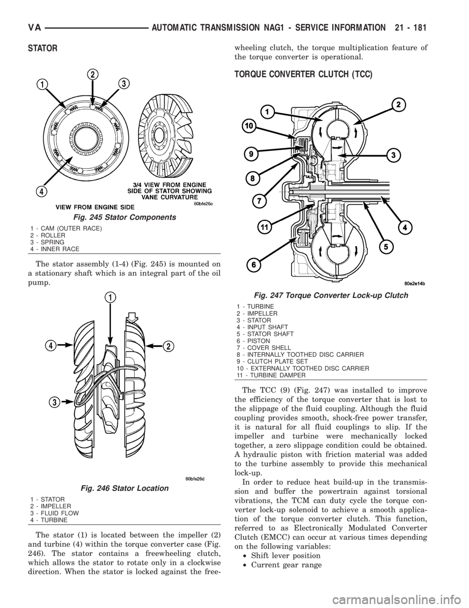
The stator assembly (1-4) (Fig. 245) is mounted on
a stationary shaft which is an integral part of the oil
pump.
The stator (1) is located between the impeller (2)
and turbine (4) within the torque converter case (Fig.
246). The stator contains a freewheeling clutch,
which allows the stator to rotate only in a clockwise
direction. When the stator is locked against the free-wheeling clutch, the torque multiplication feature of
the torque converter is operational.
TORQUE CONVERTER CLUTCH (TCC)
The TCC (9) (Fig. 247) was installed to improve
the efficiency of the torque converter that is lost to
the slippage of the fluid coupling. Although the fluid
coupling provides smooth, shock-free power transfer,
it is natural for all fluid couplings to slip. If the
impeller and turbine were mechanically locked
together, a zero slippage condition could be obtained.
A hydraulic piston with friction material was added
to the turbine assembly to provide this mechanical
lock-up.
In order to reduce heat build-up in the transmis-
sion and buffer the powertrain against torsional
vibrations, the TCM can duty cycle the torque con-
verter lock-up solenoid to achieve a smooth applica-
tion of the torque converter clutch. This function,
referred to as Electronically Modulated Converter
Clutch (EMCC) can occur at various times depending
on the following variables:
²Shift lever position
²Current gear range
Fig. 245 Stator Components
1 - CAM (OUTER RACE)
2 - ROLLER
3 - SPRING
4 - INNER RACE
Fig. 246 Stator Location
1-STATOR
2 - IMPELLER
3 - FLUID FLOW
4 - TURBINE
Fig. 247 Torque Converter Lock-up Clutch
1 - TURBINE
2 - IMPELLER
3-STATOR
4 - INPUT SHAFT
5 - STATOR SHAFT
6 - PISTON
7 - COVER SHELL
8 - INTERNALLY TOOTHED DISC CARRIER
9 - CLUTCH PLATE SET
10 - EXTERNALLY TOOTHED DISC CARRIER
11 - TURBINE DAMPER
VAAUTOMATIC TRANSMISSION NAG1 - SERVICE INFORMATION 21 - 181
Page 1925 of 2305
²Transmission fluid temperature
²Engine coolant temperature
²Input speed
²Throttle angle
²Engine speed
OPERATION
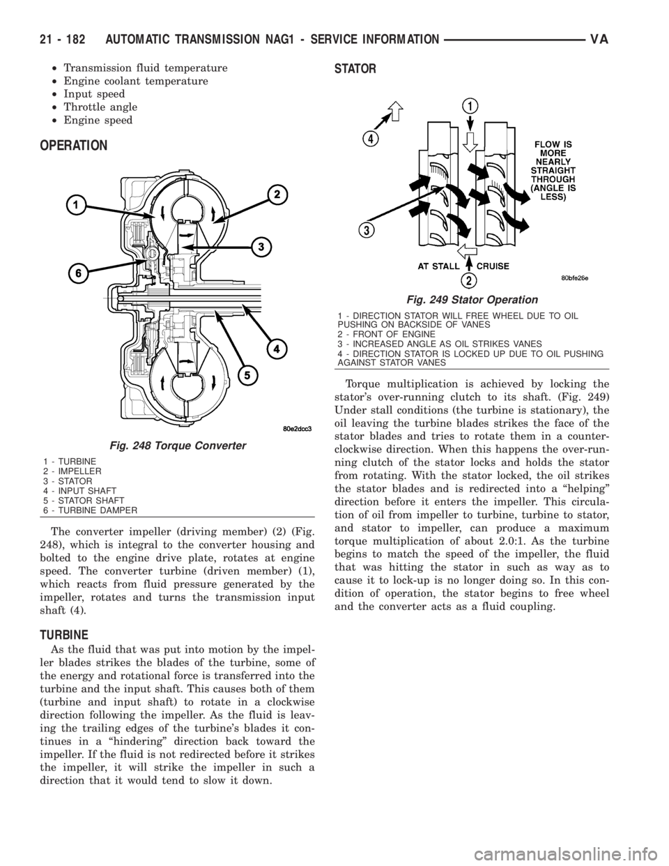
The converter impeller (driving member) (2) (Fig.
248), which is integral to the converter housing and
bolted to the engine drive plate, rotates at engine
speed. The converter turbine (driven member) (1),
which reacts from fluid pressure generated by the
impeller, rotates and turns the transmission input
shaft (4).
TURBINE
As the fluid that was put into motion by the impel-
ler blades strikes the blades of the turbine, some of
the energy and rotational force is transferred into the
turbine and the input shaft. This causes both of them
(turbine and input shaft) to rotate in a clockwise
direction following the impeller. As the fluid is leav-
ing the trailing edges of the turbine's blades it con-
tinues in a ªhinderingº direction back toward the
impeller. If the fluid is not redirected before it strikes
the impeller, it will strike the impeller in such a
direction that it would tend to slow it down.
STATOR
Torque multiplication is achieved by locking the
stator's over-running clutch to its shaft. (Fig. 249)
Under stall conditions (the turbine is stationary), the
oil leaving the turbine blades strikes the face of the
stator blades and tries to rotate them in a counter-
clockwise direction. When this happens the over-run-
ning clutch of the stator locks and holds the stator
from rotating. With the stator locked, the oil strikes
the stator blades and is redirected into a ªhelpingº
direction before it enters the impeller. This circula-
tion of oil from impeller to turbine, turbine to stator,
and stator to impeller, can produce a maximum
torque multiplication of about 2.0:1. As the turbine
begins to match the speed of the impeller, the fluid
that was hitting the stator in such as way as to
cause it to lock-up is no longer doing so. In this con-
dition of operation, the stator begins to free wheel
and the converter acts as a fluid coupling.
Fig. 248 Torque Converter
1 - TURBINE
2 - IMPELLER
3-STATOR
4 - INPUT SHAFT
5 - STATOR SHAFT
6 - TURBINE DAMPER
Fig. 249 Stator Operation
1 - DIRECTION STATOR WILL FREE WHEEL DUE TO OIL
PUSHING ON BACKSIDE OF VANES
2 - FRONT OF ENGINE
3 - INCREASED ANGLE AS OIL STRIKES VANES
4 - DIRECTION STATOR IS LOCKED UP DUE TO OIL PUSHING
AGAINST STATOR VANES
21 - 182 AUTOMATIC TRANSMISSION NAG1 - SERVICE INFORMATIONVA
Page 1926 of 2305
TORQUE CONVERTER CLUTCH (TCC)
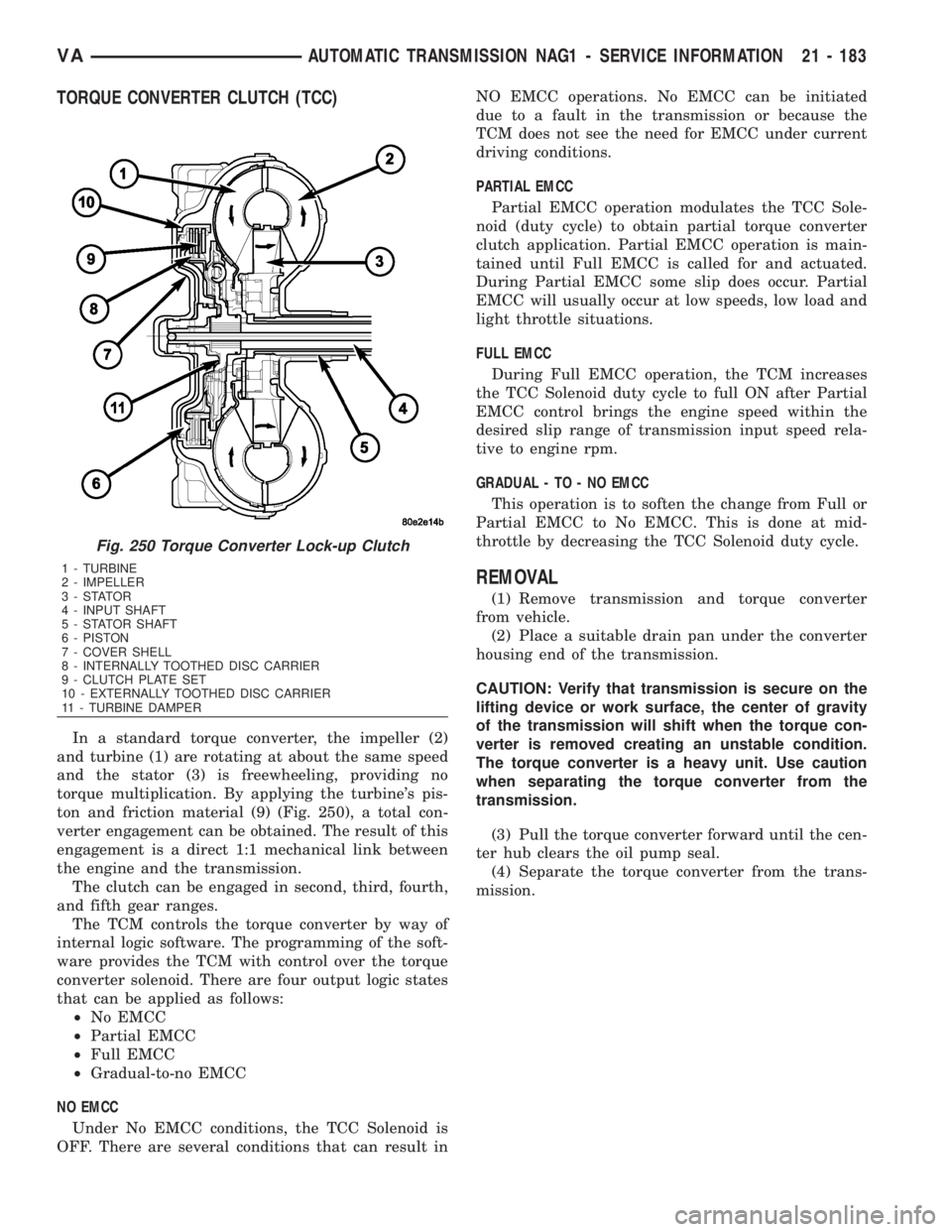
In a standard torque converter, the impeller (2)
and turbine (1) are rotating at about the same speed
and the stator (3) is freewheeling, providing no
torque multiplication. By applying the turbine's pis-
ton and friction material (9) (Fig. 250), a total con-
verter engagement can be obtained. The result of this
engagement is a direct 1:1 mechanical link between
the engine and the transmission.
The clutch can be engaged in second, third, fourth,
and fifth gear ranges.
The TCM controls the torque converter by way of
internal logic software. The programming of the soft-
ware provides the TCM with control over the torque
converter solenoid. There are four output logic states
that can be applied as follows:
²No EMCC
²Partial EMCC
²Full EMCC
²Gradual-to-no EMCC
NO EMCC
Under No EMCC conditions, the TCC Solenoid is
OFF. There are several conditions that can result inNO EMCC operations. No EMCC can be initiated
due to a fault in the transmission or because the
TCM does not see the need for EMCC under current
driving conditions.
PARTIAL EMCC
Partial EMCC operation modulates the TCC Sole-
noid (duty cycle) to obtain partial torque converter
clutch application. Partial EMCC operation is main-
tained until Full EMCC is called for and actuated.
During Partial EMCC some slip does occur. Partial
EMCC will usually occur at low speeds, low load and
light throttle situations.
FULL EMCC
During Full EMCC operation, the TCM increases
the TCC Solenoid duty cycle to full ON after Partial
EMCC control brings the engine speed within the
desired slip range of transmission input speed rela-
tive to engine rpm.
GRADUAL - TO - NO EMCC
This operation is to soften the change from Full or
Partial EMCC to No EMCC. This is done at mid-
throttle by decreasing the TCC Solenoid duty cycle.
REMOVAL
(1) Remove transmission and torque converter
from vehicle.
(2) Place a suitable drain pan under the converter
housing end of the transmission.
CAUTION: Verify that transmission is secure on the
lifting device or work surface, the center of gravity
of the transmission will shift when the torque con-
verter is removed creating an unstable condition.
The torque converter is a heavy unit. Use caution
when separating the torque converter from the
transmission.
(3) Pull the torque converter forward until the cen-
ter hub clears the oil pump seal.
(4) Separate the torque converter from the trans-
mission.
Fig. 250 Torque Converter Lock-up Clutch
1 - TURBINE
2 - IMPELLER
3-STATOR
4 - INPUT SHAFT
5 - STATOR SHAFT
6 - PISTON
7 - COVER SHELL
8 - INTERNALLY TOOTHED DISC CARRIER
9 - CLUTCH PLATE SET
10 - EXTERNALLY TOOTHED DISC CARRIER
11 - TURBINE DAMPER
VAAUTOMATIC TRANSMISSION NAG1 - SERVICE INFORMATION 21 - 183
Page 1928 of 2305
TIRES / WHEELS
TABLE OF CONTENTS
page page
TIRES/WHEELS
DIAGNOSIS AND TESTING - TIRE AND
WHEEL RUNOUT......................1
STANDARD PROCEDURE
STANDARD PROCEDURE - MATCH
MOUNTING...........................2
STANDARD PROCEDURE - TIRE AND
WHEEL BALANCE......................4
STANDARD PROCEDURE - TIRE ROTATION . 6
SPECIFICATIONS
TORQUE CHART......................7
TIRES
DESCRIPTION
DESCRIPTION - TIRES..................7
DESCRIPTION - RADIAL ± PLY TIRES......7
DESCRIPTION - TIRE PRESSURE FOR
HIGH SPEEDS.........................8
DESCRIPTION - REPLACEMENT TIRES.....8
DESCRIPTION - TIRE INFLATION
PRESSURES..........................8
DIAGNOSIS AND TESTING
DIAGNOSIS AND TESTING - PRESSURE
GAUGES.............................9
DIAGNOSIS AND TESTING - TIRE NOISE
OR VIBRATION........................9
DIAGNOSIS AND TESTING - TREAD WEAR
INDICATORS..........................9DIAGNOSIS AND TESTING - TIRE WEAR
PATTERNS...........................9
DIAGNOSIS AND TESTING - TIRE/VEHICLE
LEAD...............................10
STANDARD PROCEDURE - REPAIRING
LEAKS..............................12
CLEANING............................12
SPECIFICATIONS
TIRES..............................12
SPARE TIRE CARRIER
REMOVAL.............................12
INSTALLATION.........................12
WHEELS
DESCRIPTION.........................13
OPERATION...........................13
DIAGNOSIS AND TESTING
WHEEL INSPECTION..................13
STANDARD PROCEDURE
STANDARD PROCEDURE - WHEEL
REPLACEMENT.......................13
STANDARD PROCEDURE - DUAL REAR
WHEEL INSTALLATION.................13
REMOVAL.............................14
INSTALLATION.........................15
TIRES / WHEELS
DIAGNOSIS AND TESTING - TIRE AND WHEEL
RUNOUT
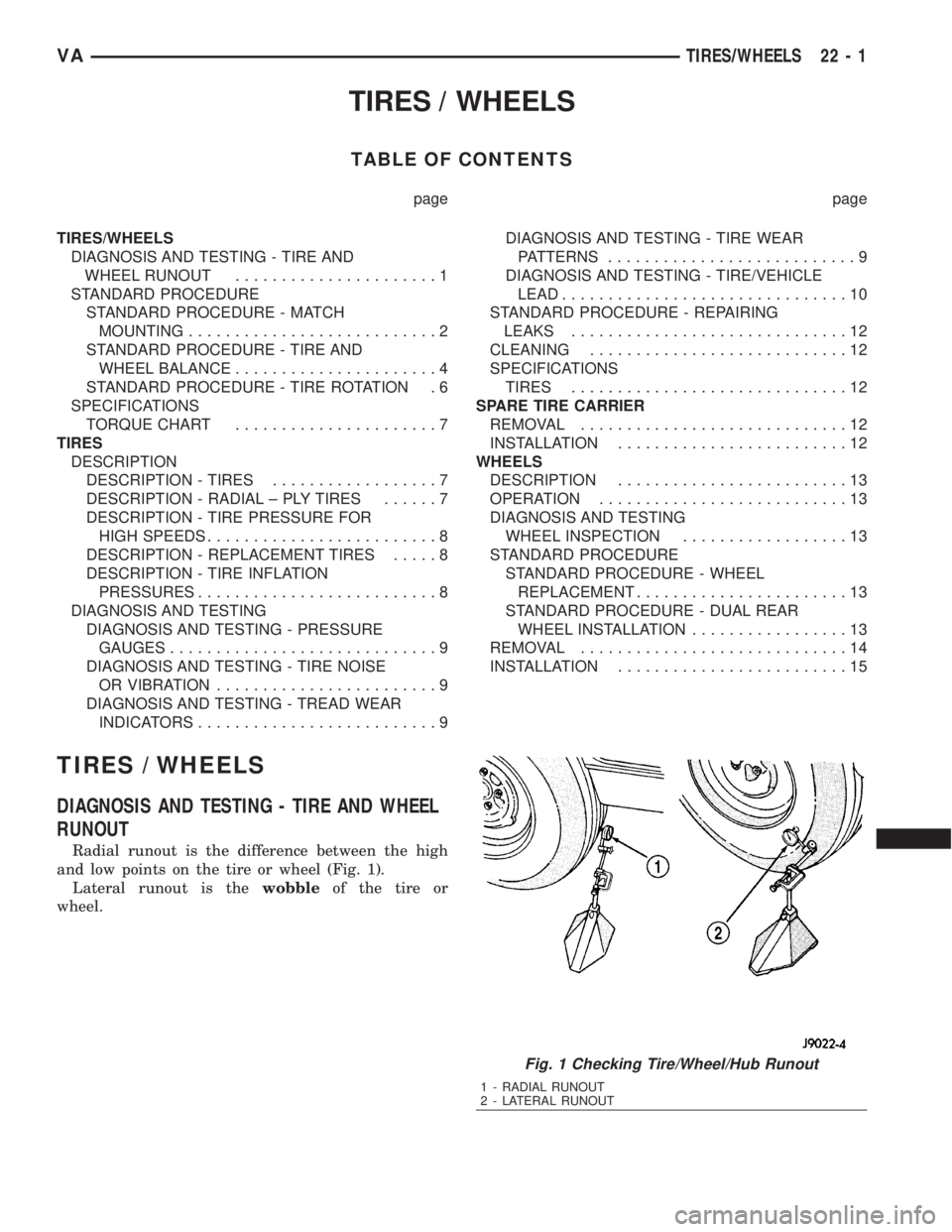
Radial runout is the difference between the high
and low points on the tire or wheel (Fig. 1).
Lateral runout is thewobbleof the tire or
wheel.
Fig. 1 Checking Tire/Wheel/Hub Runout
1 - RADIAL RUNOUT
2 - LATERAL RUNOUT
VATIRES/WHEELS 22 - 1
Page 1929 of 2305
Radial runout of more than 1.5 mm (.060 inch)
measured at the center line of the tread may cause
the vehicle to shake.
Lateral runout of more than 2.0 mm (.080 inch)
measured near the shoulder of the tire may cause the
vehicle to shake.
Sometimes radial runout can be reduced. Relocate
the wheel and tire assembly on the mounting studs
(See Method 1). If this does not reduce runout to an
acceptable level, the tire can be rotated on the wheel.
(See Method 2).
METHOD 1 (RELOCATE WHEEL ON HUB)
(1) Drive vehicle a short distance to eliminate tire
flat spotting from a parked position.
(2) Check wheel bearings and adjust if adjustable
or replace if necessary.
(3) Check the wheel mounting surface.
(4) Relocate wheel on the mounting, two studs
over from the original position.
(5) Tighten wheel nuts until all are properly
torqued, to eliminate brake distortion.
(6) Check radial runout. If still excessive, mark
tire sidewall, wheel, and stud at point of maximum
runout and proceed to Method 2.
METHOD 2 (RELOCATE TIRE ON WHEEL)
NOTE: Rotating the tire on wheel is particularly
effective when there is runout in both tire and
wheel.
(1) Remove tire from wheel and mount wheel on
service dynamic balance machine.
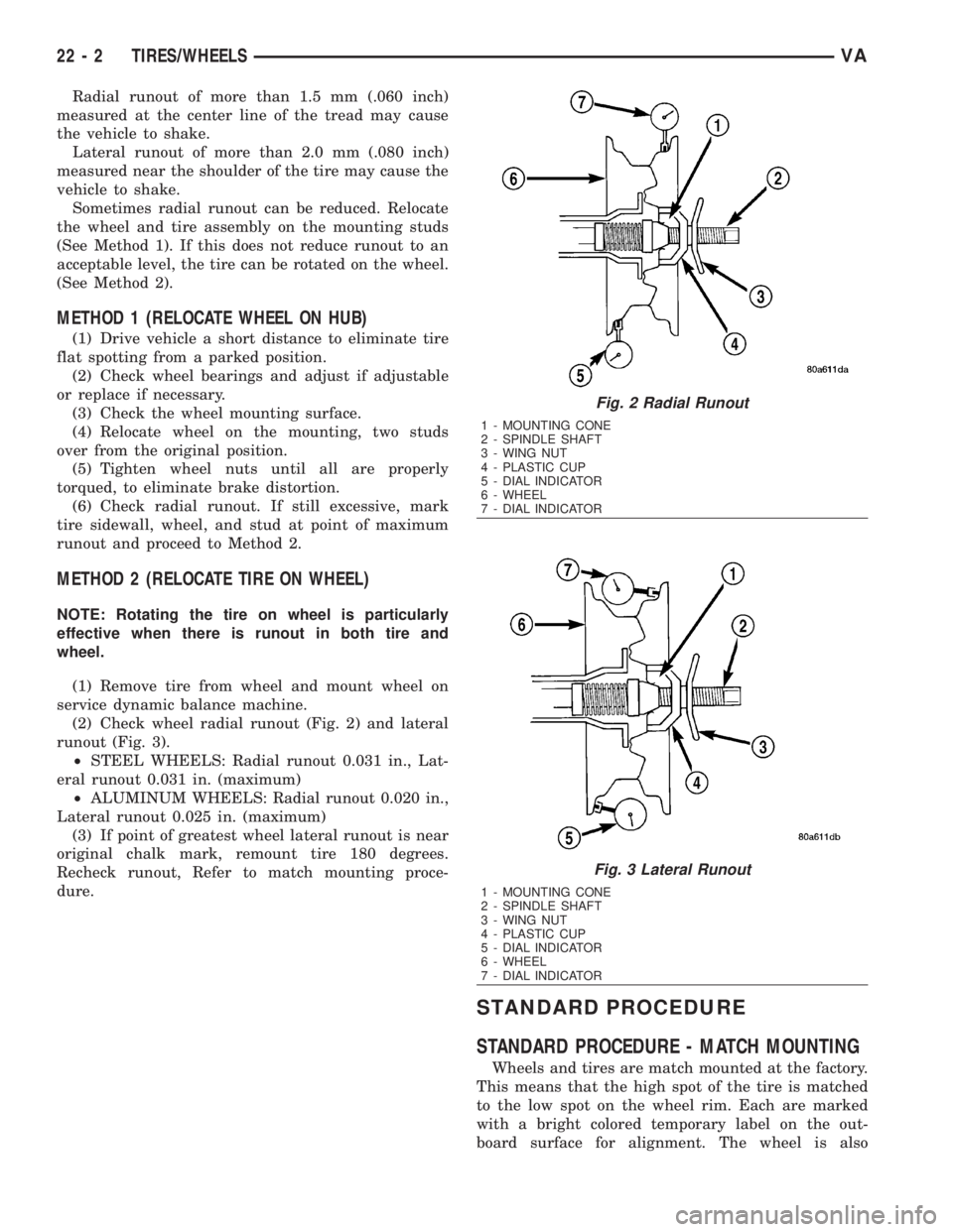
(2) Check wheel radial runout (Fig. 2) and lateral
runout (Fig. 3).
²STEEL WHEELS: Radial runout 0.031 in., Lat-
eral runout 0.031 in. (maximum)
²ALUMINUM WHEELS: Radial runout 0.020 in.,
Lateral runout 0.025 in. (maximum)
(3) If point of greatest wheel lateral runout is near
original chalk mark, remount tire 180 degrees.
Recheck runout, Refer to match mounting proce-
dure.
STANDARD PROCEDURE
STANDARD PROCEDURE - MATCH MOUNTING
Wheels and tires are match mounted at the factory.
This means that the high spot of the tire is matched
to the low spot on the wheel rim. Each are marked
with a bright colored temporary label on the out-
board surface for alignment. The wheel is also
Fig. 2 Radial Runout
1 - MOUNTING CONE
2 - SPINDLE SHAFT
3 - WING NUT
4 - PLASTIC CUP
5 - DIAL INDICATOR
6 - WHEEL
7 - DIAL INDICATOR
Fig. 3 Lateral Runout
1 - MOUNTING CONE
2 - SPINDLE SHAFT
3 - WING NUT
4 - PLASTIC CUP
5 - DIAL INDICATOR
6 - WHEEL
7 - DIAL INDICATOR
22 - 2 TIRES/WHEELSVA
Page 1934 of 2305
SPECIFICATIONS
TORQUE CHART
TORQUE SPECIFICATIONS
DESCRIPTION N´m Ft. Lbs. In. Lbs.
3500 Series 190 +10 140 +10 ±
2500 Series 240 +10 177 +10 ±
TIRES
DESCRIPTION
DESCRIPTION - TIRES
Tires are designed and engineered for each specific
vehicle. They provide the best overall performance
for normal operation. The ride and handling charac-
teristics match the vehicle's requirements. With
proper care they will give excellent reliability, trac-
tion, skid resistance, and tread life.
Driving habits have more effect on tire life than
any other factor. Careful drivers will obtain in most
cases, much greater mileage than severe use or care-
less drivers. A few of the driving habits which will
shorten the life of any tire are:
²Rapid acceleration
²Severe brake applications
²High speed driving
²Excessive speeds on turns
²Striking curbs and other obstacles
Radial-ply tires are more prone to irregular tread
wear. It is important to follow the tire rotation inter-
val shown in the section on Tire Rotation, (Refer to
22 - TIRES/WHEELS - STANDARD PROCEDURE).
This will help to achieve a greater tread life.
TIRE IDENTIFICATION
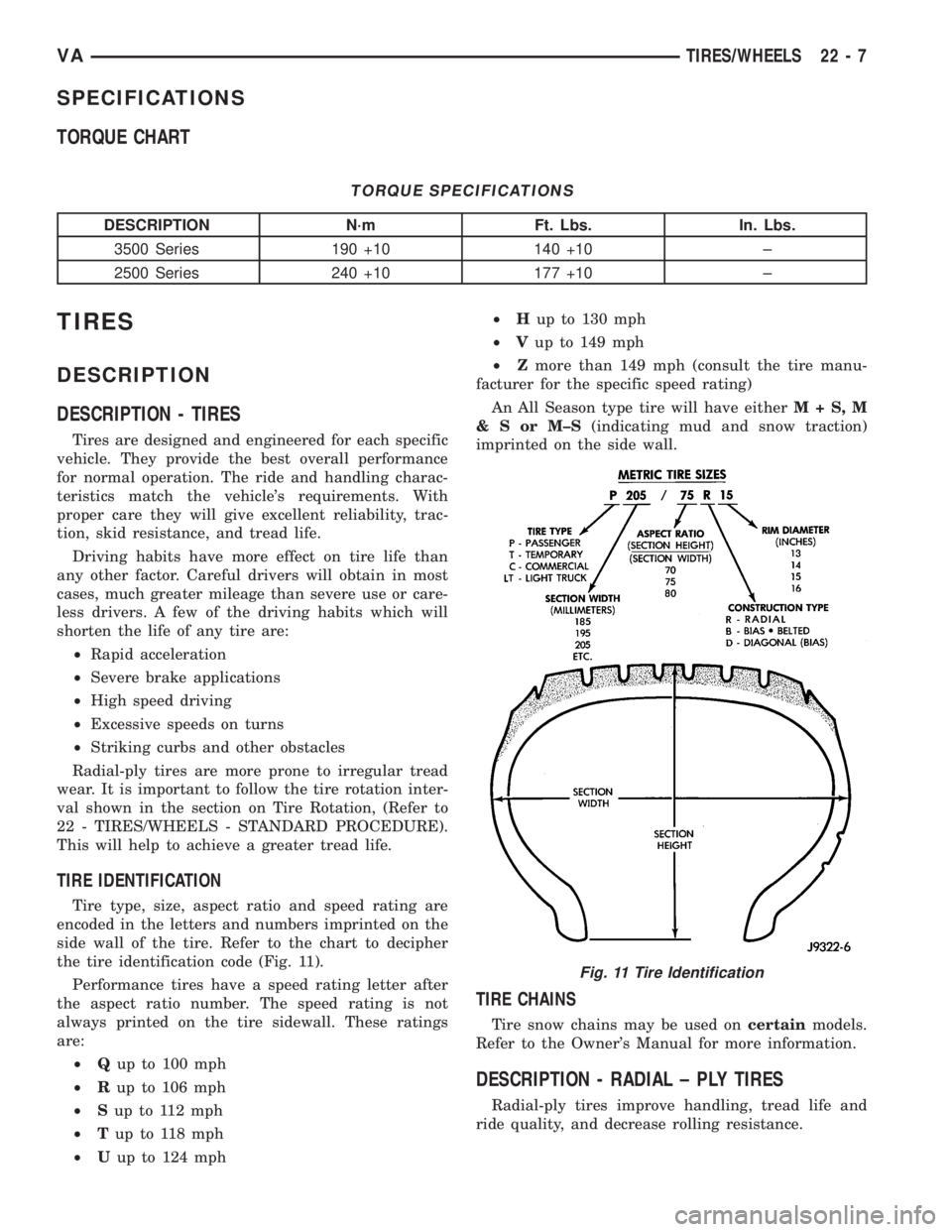
Tire type, size, aspect ratio and speed rating are
encoded in the letters and numbers imprinted on the
side wall of the tire. Refer to the chart to decipher
the tire identification code (Fig. 11).
Performance tires have a speed rating letter after
the aspect ratio number. The speed rating is not
always printed on the tire sidewall. These ratings
are:
²Qup to 100 mph
²Rup to 106 mph
²Sup to 112 mph
²Tup to 118 mph
²Uup to 124 mph²Hup to 130 mph
²Vup to 149 mph
²Zmore than 149 mph (consult the tire manu-
facturer for the specific speed rating)
An All Season type tire will have eitherM+S,M
&SorM±S(indicating mud and snow traction)
imprinted on the side wall.
TIRE CHAINS
Tire snow chains may be used oncertainmodels.
Refer to the Owner's Manual for more information.
DESCRIPTION - RADIAL ± PLY TIRES
Radial-ply tires improve handling, tread life and
ride quality, and decrease rolling resistance.
Fig. 11 Tire Identification
VATIRES/WHEELS 22 - 7
Page 1939 of 2305
STANDARD PROCEDURE - REPAIRING LEAKS
For proper repairing, a radial tire must be removed
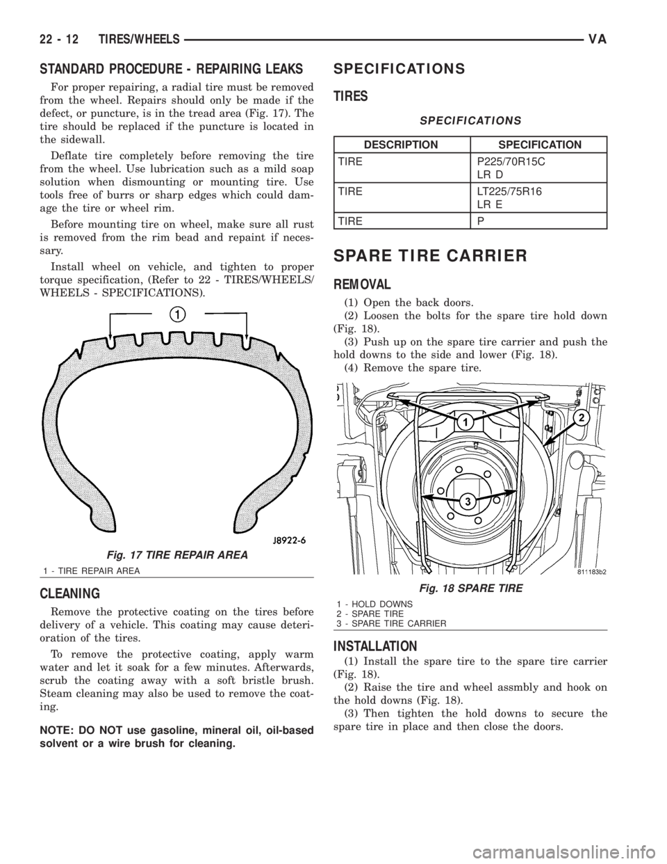
from the wheel. Repairs should only be made if the
defect, or puncture, is in the tread area (Fig. 17). The
tire should be replaced if the puncture is located in
the sidewall.
Deflate tire completely before removing the tire
from the wheel. Use lubrication such as a mild soap
solution when dismounting or mounting tire. Use
tools free of burrs or sharp edges which could dam-
age the tire or wheel rim.
Before mounting tire on wheel, make sure all rust
is removed from the rim bead and repaint if neces-
sary.
Install wheel on vehicle, and tighten to proper
torque specification, (Refer to 22 - TIRES/WHEELS/
WHEELS - SPECIFICATIONS).
CLEANING
Remove the protective coating on the tires before
delivery of a vehicle. This coating may cause deteri-
oration of the tires.
To remove the protective coating, apply warm
water and let it soak for a few minutes. Afterwards,
scrub the coating away with a soft bristle brush.
Steam cleaning may also be used to remove the coat-
ing.
NOTE: DO NOT use gasoline, mineral oil, oil-based
solvent or a wire brush for cleaning.
SPECIFICATIONS
TIRES
SPECIFICATIONS
DESCRIPTION SPECIFICATION
TIRE P225/70R15C
LR D
TIRE LT225/75R16
LR E
TIRE P
SPARE TIRE CARRIER
REMOVAL
(1) Open the back doors.
(2) Loosen the bolts for the spare tire hold down
(Fig. 18).
(3) Push up on the spare tire carrier and push the
hold downs to the side and lower (Fig. 18).
(4) Remove the spare tire.
INSTALLATION
(1) Install the spare tire to the spare tire carrier
(Fig. 18).
(2) Raise the tire and wheel assmbly and hook on
the hold downs (Fig. 18).
(3) Then tighten the hold downs to secure the
spare tire in place and then close the doors.
Fig. 17 TIRE REPAIR AREA
1 - TIRE REPAIR AREA
Fig. 18 SPARE TIRE
1 - HOLD DOWNS
2 - SPARE TIRE
3 - SPARE TIRE CARRIER
22 - 12 TIRES/WHEELSVA