2006 MERCEDES-BENZ SPRINTER rear view mirror
[x] Cancel search: rear view mirrorPage 2028 of 2305

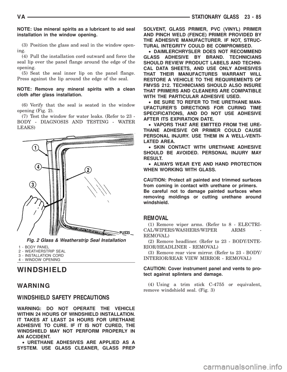
NOTE: Use mineral spirits as a lubricant to aid seal
installation in the window opening.
(3) Position the glass and seal in the window open-
ing.
(4) Pull the installation cord outward and force the
seal lip over the panel flange around the edge of the
opening.
(5) Seat the seal inner lip on the panel flange.
Press against the lip around the edge of the seal.
NOTE: Remove any mineral spirits with a clean
cloth after glass installation.
(6) Verify that the seal is seated in the window
opening (Fig. 2).
(7) Test the window for water leaks. (Refer to 23 -
BODY - DIAGNOSIS AND TESTING - WATER
LEAKS)
WINDSHIELD
WARNING
WINDSHIELD SAFETY PRECAUTIONS
WARNING: DO NOT OPERATE THE VEHICLE
WITHIN 24 HOURS OF WINDSHIELD INSTALLATION.
IT TAKES AT LEAST 24 HOURS FOR URETHANE
ADHESIVE TO CURE. IF IT IS NOT CURED, THE
WINDSHIELD MAY NOT PERFORM PROPERLY IN
AN ACCIDENT.
²URETHANE ADHESIVES ARE APPLIED AS A
SYSTEM. USE GLASS CLEANER, GLASS PREPSOLVENT, GLASS PRIMER, PVC (VINYL) PRIMER
AND PINCH WELD (FENCE) PRIMER PROVIDED BY
THE ADHESIVE MANUFACTURER. IF NOT, STRUC-
TURAL INTEGRITY COULD BE COMPROMISED.
²DAIMLERCHRYSLER DOES NOT RECOMMEND
GLASS ADHESIVE BY BRAND. TECHNICIANS
SHOULD REVIEW PRODUCT LABELS AND TECHNI-
CAL DATA SHEETS, AND USE ONLY ADHESIVES
THAT THEIR MANUFACTURES WARRANT WILL
RESTORE A VEHICLE TO THE REQUIREMENTS OF
FMVSS 212. TECHNICIANS SHOULD ALSO INSURE
THAT PRIMERS AND CLEANERS ARE COMPATIBLE
WITH THE PARTICULAR ADHESIVE USED.
²BE SURE TO REFER TO THE URETHANE MAN-
UFACTURER'S DIRECTIONS FOR CURING TIME
SPECIFICATIONS, AND DO NOT USE ADHESIVE
AFTER ITS EXPIRATION DATE.
²VAPORS THAT ARE EMITTED FROM THE URE-
THANE ADHESIVE OR PRIMER COULD CAUSE
PERSONAL INJURY. USE THEM IN A WELL-VENTI-
LATED AREA.
²SKIN CONTACT WITH URETHANE ADHESIVE
SHOULD BE AVOIDED. PERSONAL INJURY MAY
RESULT.
²ALWAYS WEAR EYE AND HAND PROTECTION
WHEN WORKING WITH GLASS.
CAUTION: Protect all painted and trimmed surfaces
from coming in contact with urethane or primers.
Be careful not to damage painted surfaces when
removing moldings or cutting urethane around
windshield.
REMOVAL
(1) Remove wiper arms. (Refer to 8 - ELECTRI-
CAL/WIPERS/WASHERS/WIPER ARMS -
REMOVAL)
(2) Remove headliner. (Refer to 23 - BODY/INTE-
RIOR/HEADLINER - REMOVAL)
(3) Remove rear view mirror. (Refer to 23 - BODY/
INTERIOR/REAR VIEW MIRROR - REMOVAL)
CAUTION: Cover instrument panel and vents to pro-
tect against splinters and damage.
(4) Using a trim stick C-4755 or equivalent,
remove windshield seal. (Fig. 3)
Fig. 2 Glass & Weatherstrip Seal Installation
1 - BODY PANEL
2 - WEATHERSTRIP SEAL
3 - INSTALLATION CORD
4 - WINDOW OPENING
VASTATIONARY GLASS 23 - 85
Page 2032 of 2305

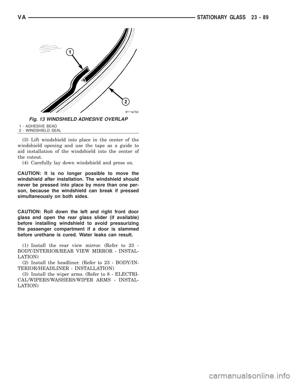
(3) Lift windshield into place in the center of the
windshield opening and use the tape as a guide to
aid installation of the windshield into the center of
the cutout.
(4) Carefully lay down windshield and press on.
CAUTION: It is no longer possible to move the
windshield after installation. The windshield should
never be pressed into place by more than one per-
son, because the windshield can break if pressed
simultaneously on both sides.
CAUTION: Roll down the left and right front door
glass and open the rear glass slider (if available)
before installing windshield to avoid pressurizing
the passenger compartment if a door is slammed
before urethane is cured. Water leaks can result.
(1) Install the rear view mirror. (Refer to 23 -
BODY/INTERIOR/REAR VIEW MIRROR - INSTAL-
LATION)
(2) Install the headliner. (Refer to 23 - BODY/IN-
TERIOR/HEADLINER - INSTALLATION)
(3) Install the wiper arms. (Refer to 8 - ELECTRI-
CAL/WIPERS/WASHERS/WIPER ARMS - INSTAL-
LATION)
Fig. 13 WINDSHIELD ADHESIVE OVERLAP
1 - ADHESIVE BEAD
2 - WINDSHIELD SEAL
VASTATIONARY GLASS 23 - 89
Page 2159 of 2305

INSIDE HANDLE ACTUATOR......23-33, 23-36
INSTRUMENT CLUSTER................8J-2
INSTRUMENT PANEL ANTENNA CABLE....8A-2
INSTRUMENT PANEL ASSEMBLY........23-59
INSTRUMENT PANEL CENTER BEZEL.....23-57
INSTRUMENT PANEL DUCTS...........24-51
INTAKE AIR PRESSURE SENSOR........14-43
INTAKE AIR TEMPERATURE SENSOR.....14-42
INTAKE MANIFOLD....................9-65
INTERIOR..........................23-70
INTERMEDIATE SHAFT.................19-4
INTERNATIONAL SYMBOLS...............0-9
INTERNATIONAL SYMBOLS...........Intro.-2
INTRUSION SENSOR...................8Q-1
IN - CAR TEMPERATURE SENSOR.......24-21
JUMP STARTING.......................0-6
KEY / LOCK CYLINDER.................19-5
KNUCKLE.............................2-5
LAMPS / LIGHTING - EXTERIOR..........8L-2
LAMPS / LIGHTING - INTERIOR.........8L-28
LATCH RELEASE CABLE...............23-52
LATCH RELEASE HANDLE..............23-52
LATCH STRIKER.....................23-18
LATCH ..................23-18, 23-33, 23-52
LATCH / LOCK CONTROL...............23-38
LATERAL ACCELERATION SENSOR........5-33
LEFT MOUNT.........................9-55
LEVER..............................5-26
LICENSE PLATE BRACKET..............23-48
LICENSE PLATE LAMP BULB...........8L-19
LICENSE PLATE LAMP UNIT............8L-19
LINKAGE............................19-9
LIQUID LINE........................24-77
LOCK CYLINDER.....................23-18
LOW BEAM HEADLAMP BULB..........8L-20
LOW FUEL INDICATOR................8J-19
LOW OIL LEVEL INDICATOR............8J-20
LOWER BALL JOINT....................2-6
LOWER CONTROL ARM.................2-6
LOWER ROLLER ARM.................23-37
MAINTENANCE INDICATOR.............8J-20
MAINTENANCE SCHEDULES..............0-8
MALFUNCTION INDICATOR LAMP (MIL) . . . 8J-21
MANIFOLD AIR FLOW (MAF) SENSOR....14-44
MASTER CYLINDER...................5-17
MASTER LOCK SWITCH................8N-1
METRIC SYSTEM...................Intro.-6
MODE DOOR CABLES.................24-21
MULTI - FUNCTION INDICATOR..........8J-22
MULTI - FUNCTION SWITCH............8L-21
O2 SENSOR.........................14-45
ODOMETER.........................8J-22
OIL COOLER & LINES..................9-56
OIL FILTER ..........................9-57
OIL JET .............................9-57
OIL PAN .............................9-58
OIL PUMP...........................9-61
OIL PUMP.........................21-154
OIL SENSOR.........................9-64
OIL ................................9-56
OPENING DIMENSIONS................23-93
OUTPUT SHAFT BEARING.............21-156
OUTPUT SHAFT SEAL................21-159
PAINT TOUCH - UP...................23-77
PAINT.............................23-77
PARK BRAKE INDICATOR..............8J-23
PARK BRAKE SWITCH.................8L-21
PARK LOCK CABLE..................21-160
PARKING BRAKE......................5-23
PASSENGER AIRBAG BRACKET.........8O-27
PASSENGER AIRBAG.................8O-24
PASSENGER HEATED SEAT SWITCH.....8G-13
PEDAL..............................5-19
PISTON & CONNECTING ROD............9-45
PISTON RINGS.......................9-52
PISTONS..........................21-163
PLANETARY GEARTRAIN..............21-164
PLUMBING.........................24-61
POWER BRAKE BOOSTER...............5-19
POWER DISTRIBUTION CENTER.......8W-97-3
POWER DISTRIBUTION..............8W-97-1
POWER MIRROR SWITCH..............8N-3
POWER MIRRORS....................8N-3
POWER OUTLET
...................8W-97-3
POWER WINDOW SWITCH
..............8N-5
POWER WINDOWS
....................8N-5
PROP ROD
.........................23-53
PROPELLER SHAFT
.................3-1, 3-7PUMP.............................19-11
QUARTER TRIM PANEL................23-74
QUARTER WINDOW..................23-84
RADIATOR CROSSMEMBER............23-49
RADIATOR FAN.......................7-14
RADIATOR PRESSURE CAP..............7-19
RADIATOR...........................7-17
RADIO..............................8A-2
RAIN SENSOR CONTROL MODULE......8R-15
RAIN SENSOR.......................8R-12
REAR AXLE..........................3-12
REAR A / C CONDENSER FAN...........24-83
REAR A / C EVAPORATOR..............24-84
REAR A / C EXPANSION VALVE..........24-85
REAR BUMPER - STEP.................13-2
REAR CROSSMEMBER - TRANSMISSION . . 13-11
REAR DISCHARGE LINE...............24-88
REAR FASCIA........................13-3
REAR LATCH STRIKER................23-40
REAR LATCH........................23-40
REAR LIQUID LINE...................24-91
REAR RECEIVER / DRIER..............24-94
REAR REFRIGERANT RESERVOIR........24-95
REAR SEAT BACK SHIELD..............23-82
REAR SEAT BELT & RETRACTOR........8O-28
REAR SEAT BELT BUCKLE.............8O-30
REAR SIDE MARKER LAMP BULB.......8L-22
REAR SUCTION LINE..................24-96
REAR TURN LAMP BULB..............8L-23
REAR VIEW MIRROR.................23-75
REAR WHEEL SPEED SENSOR...........5-31
REAR WINDOW DEFOGGER GRID........8G-7
REAR WINDOW DEFOGGER RELAY.......8G-3
REAR WINDOW DEFOGGER SWITCH......8G-4
REAR...............................2-11
RECEIVER / DRIER...................24-79
RECIRCULATION DOOR ACTUATOR......24-22
REFRIGERANT LINE COUPLER..........24-98
REFRIGERANT OIL...................24-81
REFRIGERANT.......................24-80
RELAY...........................8W-97-4
REMOTE KEYLESS ENTRY
TRANSMITTER.......................8N-1
REPEATER LAMP BULB................8L-23
REPEATER LAMP UNIT................8L-24
RESTRAINTS.........................8O-2
RIGHT MOUNT.......................9-56
ROTORS............................5-20
SAFETY LATCH......................23-53
SEAL - PINION........................3-39
SEAT ADJUSTERS - FRONT.............23-81
SEAT BACK CUSHION / COVER - REAR....23-82
SEAT BACK - FRONT..................23-80
SEAT BELT SWITCH..................8O-31
SEAT BELT TENSIONER................8O-32
SEAT BELT TURNING LOOP ADJUSTER . . . 8O-33
SEAT CUSHION - FRONT...............23-80
SEAT CUSHION / COVER - REAR.........23-83
SEATBELT INDICATOR.................8J-24
SEAT - FRONT.......................23-79
SEAT - REAR........................23-81
SECURITY SYSTEM MODULE............8Q-2
SENTRY KEY REMOTE ENTRY MODULE....8Q-2
SERVO..............................8P-2
SHAFT - AXLE DUAL REAR WHEELS......3-27
SHAFT - AXLE SINGLE REAR WHEEL......3-23
SHIFT MECHANISM..................21-168
SHOCK..............................2-13
SHOES..............................5-27
SIDE CURTAIN AIRBAG................8O-35
SIDE IMPACT SENSOR................8O-39
SIDE VIEW MIRROR..................23-49
SIDE VIEW MIRROR - GLASS...........23-50
SIREN..............................8Q-4
SLIDING DOOR......................23-40
SOLENOID.........................21-171
SPARE TIRE CARRIER.................22-12
SPEAKER............................8A-2
SPEED CONTROL.....................8P-1
SPEEDOMETER......................8J-25
SPRING CLAMP PLATES.................2-8
SPRING SHACKLE.....................2-15
SPRING STOP PLATES..................2-9
SPRING
.........................2-7, 2-14
STABILIZER BAR
..................2-9, 2-15
STABILIZER LINK
.................2-10, 2-16
STABILIZER
.........................23-45
STARTER MOTOR RELAY
..............8F-35STARTER MOTOR....................8F-33
STARTING SYSTEM...................8F-28
STEERING ANGLE SENSOR..............5-32
STEERING COLUMN OPENING COVER....23-68
STEERING WHEEL.....................19-6
STEERING...........................19-1
STEPWELL SCUFF PADS...............23-75
STRUT..............................2-10
SUCTION LINE.......................24-81
SUN VISOR.........................23-76
SUPPORT PLATE......................5-23
SUPPRESSOR FILTER - REAR BLOWER
MOTOR............................24-41
SUPPRESSOR FILTER - REAR
CONDENSER FAN....................24-43
SWITCH.............................8P-3
TACHOMETER.......................8J-25
TAIL LAMP UNIT.....................8L-25
TAILPIPE............................11-3
TEMPERATURE CONTROL..............24-38
TEMPERATURE SENSOR...............24-40
TEMPERATURE SENSOR / PARK -
NEUTRAL CONTACT..................21-176
TERMINAL........................Intro.-10
THREADED HOLE REPAIR.............Intro.-6
TIE ROD END ........................19-10
TIME DELAY RELAY....................8L-35
TIMING CHAIN AND SPROCKETS.........9-72
TIMING CHAIN COVER.................9-70
TIMING CHAIN TENSIONER..............9-81
TIRES..............................22-7
TIRES / WHEELS......................22-1
TONE WHEEL........................5-32
TOP COVER.........................23-67
TOP COVER - CLUSTER................23-64
TOP COVER - TRAY...................23-65
TORQUE CONVERTER HUB SEAL.......21-184
TORQUE CONVERTER................21-178
TORQUE REFERENCES...............Intro.-9
TOWING.............................0-7
TRACTION CONTROL INDICATOR........8J-26
TRACTION CONTROL MALFUNCTION
INDICATOR.........................8J-27
TRAILER HITCH......................13-11
TRANSMISSION CONTROL MODULE......8E-6
TRANSPONDER KEY...................8Q-5
TRIM PANEL.............23-18, 23-34, 23-46
TURBOCHARGER SYSTEM..............11-3
TURBOCHARGER......................11-6
TURN SIGNAL INDICATOR..............8J-27
TURN SIGNAL RELAY.................8L-26
UNDERBODY LINES..................24-100
UPPER ROLLER ARM.................23-36
VACUUM PUMP.......................9-54
VALVE COOLER.......................25-6
VALVE SPRINGS......................9-35
VALVE STEM SEALS...................9-34
VALVE ..............................25-5
VEHICLE IDENTIFICATION NUMBER.....Intro.-1
VEHICLE THEFT SECURITY..............8Q-1
VIBRATION DAMPER...................9-53
VOLTAGE REGULATOR.................8F-24
WAIT - TO - START INDICATOR..........8J-28
WASHER FLUID INDICATOR............8J-29
WASHER FLUID LEVEL SWITCH.........8R-16
WASHER HOSES / TUBES..............8R-18
WASHER NOZZLE....................8R-18
WASHER PUMP / MOTOR..............8R-19
WASHER RESERVOIR.................8R-21
WATER IN FUEL SENSOR..............14-30
WATER PUMP........................7-20
WATER VALVE .......................24-83
WATER - IN - FUEL INDICATOR..........8J-29
WHEEL ALIGNMENT...................2-17
WHEELS...........................22-13
WINDOW MOTOR.....................8N-5
WINDOW REGULATOR - MANUAL........23-21
WINDOW REGULATOR - POWER........23-20
WINDSHIELD........................23-85
WIPER ARM........................8R-23
WIPER BLADE.......................8R-26
WIPER LINKAGE.....................8R-28
WIPER MOTOR......................8R-31
WIPER RELAY.......................8R-34
WIPERS/WASHERS....................8R-2
WIRING DIAGRAM INFORMATION......Intro.-1
YAW RATE SENSOR...................5-35
2 INDEXVA
Description Group-Page Description Group-Page Description Group-Page
Page 2172 of 2305

²Disconnect the live test lead before disconnecting
the common test lead.
²When using the meter function, keep the
DRBIIItaway from spark plug or coil wires to
avoid measuring error from outside interference.
4.3 WARNINGS
4.3.1 VEHICLE DAMAGE WARNINGS
Before disconnecting any control module, make
sure the ignition is9lock9position. Failure to do so
could damage the module.
When testing voltage or continuity at any control
module, use the terminal side (not the wire end) of
the connector. Do not probe a wire through the
insulation: this will damage the wire and eventu-
ally cause the wire to fail because of corrosion.
Be careful when performing electrical tests so as
to prevent accidental shorting of terminals. Such
mistakes can damage fuses or components. Also, a
second DTC could be set, making diagnosis of the
original problem more difficult.
When replacing a blown fuse, it is important to
use only a fuse having the correct amperage rating.
The use of a fuse with a rating other than indicated
may result in a dangerous electrical system over-
load. If a properly rated fuse continues to blow, it
indicates a problem in the circuit that must be
corrected.
4.3.2 ROAD TESTING A COMPLAINT
VEHICLE
Some complaints will require a test drive as part
of the repair verification procedure. The purpose of
the test drive is to try to duplicate the diagnostic
DTC or symptom condition.
CAUTION: Before road testing a vehicle, be
sure that all components are reassembled.
During the test drive, do not try to read
DRBIIITscreen while in motion. Do not hang
the DRBIIITfrom the rear view mirror or
operate it yourself. Have an assistant
available to operate the DRBIIIT.
Road testing is an essential step in the diagnostic
process that must not be overlooked. Along with the
diagnostic information obtained from the DRBIIIt
Scan Tool and the original customer concern, the
road test helps verify the problem was current and
any repairs performed, fixed the vehicle correctly.
Always operate and observe the vehicle under ac-
tual driving conditions.
Just as important as the road test is, there are
preliminary inspections that should be performed
prior to the road test. Always check the fluid leveland condition before taking the vehicle on a road
test. Determine if the incorrect fluid is being used,
improper fluid will result in erratic transmission
operation.
Some of the conditions of incorrect fluid level are as
follows:
²Delayed engagement
²Poor shifting or erratic shifting
²Excessive noise
²Overheating
The next step is to verify that the shift linkage is
correctly adjusted. If the shift linkage is incorrectly
adjusted, a number of complaints can result.
The TCM monitors the Shift Lever Position (SLP)
continuously. If the linkage is incorrectly adjusted,
the TCM will sense a shift lever position that is not
correct for the gear chosen by the driver. This may
cause a DTC to be set.
The following complaints may also be the result of
an incorrectly adjusted or worn linkage:
²Delayed clutch engagement
²Erratic shifts
²Vehicle will drive in neutral
²Engine will not crank in park or neutral
²Gear shift linkage will be able to be shifted
without the key in the ignition
²Not able to remove the ignition key in park
²Parking pawl will not engage properly
The shift linkage should also be adjusted when
replacing the Transmission, repairing the valve
body, or when repairing any component between the
shift lever and the Transmission.
Some questions to ask yourself when performing
the road test are as follows:
²Is the complaint or concern what you think the
problem is, based on the drivers description of the
problem?
²Is the Transmission operating normally, or is
there a real problem?
²When does the problem occur?
²Is the problem only in one gear range?
²What temperature does the problem occur?
²Does the vehicle have to sit over night for the
problem to occur?
²Does the transmission go into Limp-in mode?
4.4.4 BULLETINS AND RECALLS
Always perform all Safety Recalls and Technical
Service Bulletins that are applicable to the prob-
lem.
7
GENERAL INFORMATION