2006 MERCEDES-BENZ SPRINTER radiator
[x] Cancel search: radiatorPage 1581 of 2305
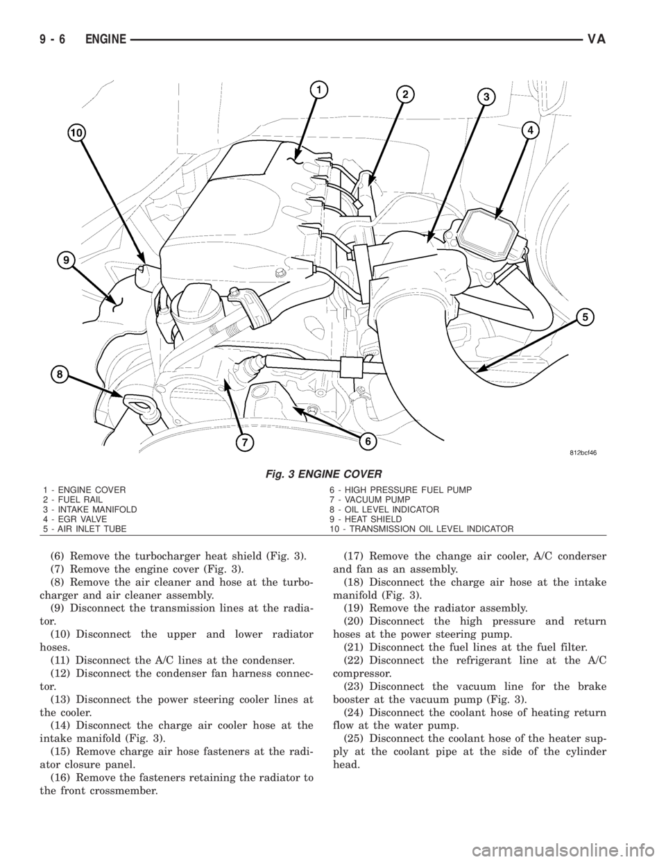
(6) Remove the turbocharger heat shield (Fig. 3).
(7) Remove the engine cover (Fig. 3).
(8) Remove the air cleaner and hose at the turbo-
charger and air cleaner assembly.
(9) Disconnect the transmission lines at the radia-
tor.
(10) Disconnect the upper and lower radiator
hoses.
(11) Disconnect the A/C lines at the condenser.
(12) Disconnect the condenser fan harness connec-
tor.
(13) Disconnect the power steering cooler lines at
the cooler.
(14) Disconnect the charge air cooler hose at the
intake manifold (Fig. 3).
(15) Remove charge air hose fasteners at the radi-
ator closure panel.
(16) Remove the fasteners retaining the radiator to
the front crossmember.(17) Remove the change air cooler, A/C conderser
and fan as an assembly.
(18) Disconnect the charge air hose at the intake
manifold (Fig. 3).
(19) Remove the radiator assembly.
(20) Disconnect the high pressure and return
hoses at the power steering pump.
(21) Disconnect the fuel lines at the fuel filter.
(22) Disconnect the refrigerant line at the A/C
compressor.
(23) Disconnect the vacuum line for the brake
booster at the vacuum pump (Fig. 3).
(24) Disconnect the coolant hose of heating return
flow at the water pump.
(25) Disconnect the coolant hose of the heater sup-
ply at the coolant pipe at the side of the cylinder
head.
Fig. 3 ENGINE COVER
1 - ENGINE COVER 6 - HIGH PRESSURE FUEL PUMP
2 - FUEL RAIL 7 - VACUUM PUMP
3 - INTAKE MANIFOLD 8 - OIL LEVEL INDICATOR
4 - EGR VALVE 9 - HEAT SHIELD
5 - AIR INLET TUBE 10 - TRANSMISSION OIL LEVEL INDICATOR
9 - 6 ENGINEVA
Page 1585 of 2305
(11) Install the torque converter access plate. Refer
to (Refer to 21 - TRANSMISSION/TRANSAXLE/AU-
TOMATIC - NAG1 - INSTALLATION) for correct
sequence and torque specification.
(12) Install the transmission cooler lines to trans-
mission. (Refer to 21 - TRANSMISSION/TRANS-
AXLE/AUTOMATIC - NAG1 - INSTALLATION) for
correct sequence and torque specification.
(13) Connect the engine valley drain hose to the
transmission (Fig. 5).
(14) Install transmission electrical connector and
shifter hardware. Refer to (Refer to 21 - TRANSMIS-
SION/TRANSAXLE/AUTOMATIC - NAG1 - INSTAL-
LATION) for correct sequence and torque
specification.
(15) Install the steering gear and tighten in two
stages. 25 N´m (18.5 lbs. ft.), then 45 N´m (33 lbs. ft.)
plus 90É.
(16) Install the starter.
(17) Connect the ground strap (left side).
(18) Align and install the exhaust and bracket
(Refer to 11 - EXHAUST SYSTEM/EXHAUST PIPE -
INSTALLATION).
(19) Lower the vehicle.
(20) Install the lower heater housing and filter.
(21) Install the air inlet hose, CCV breather and
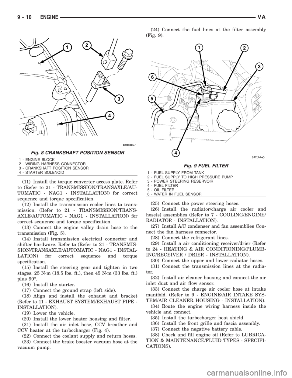
CCV heater at the turbocharger (Fig. 4).
(22) Connect the coolant supply and return hoses.
(23) Connect the brake booster vacuum hose at the
vacuum pump.(24) Connect the fuel lines at the filter assembly
(Fig. 9).
(25) Connect the power steering hoses.
(26) Install the radiator/charge air cooler and
hose(s) assemblies (Refer to 7 - COOLING/ENGINE/
RADIATOR - INSTALLATION).
(27) Install A/C condenser and fan assemblies Con-
nect the fan harness connector.
(28) Connect the refrigerant lines.
(29) Install a air conditioning receiver/drier (Refer
to 24 - HEATING & AIR CONDITIONING/PLUMB-
ING/RECEIVER / DRIER - INSTALLATION).
(30) Connect the upper and lower radiator hoses.
(31) Connect the transmission lines at the radia-
tor.
(32) Install air cleaner housing and connect the air
inlet duct and air flow sensor.
(33) Connect the charge air cooler hose at intake
manifold. (Refer to 9 - ENGINE/AIR INTAKE SYS-
TEM/AIR CLEANER HOUSING - INSTALLATION).
(34) Route the engine wiring harness inside the
vehicle and connect.
(35) Install the turbocharger heat shield.
(36) Install the front grille and fascia assembly.
(37) Connect the negative battery cable.
(38) Check and fill engine oil (Refer to LUBRICA-
TION & MAINTENANCE/FLUID TYPES - SPECIFI-
CATIONS).
Fig. 8 CRANKSHAFT POSITION SENSOR
1 - ENGINE BLOCK
2 - WIRING HARNESS CONNECTOR
3 - CRANKSHAFT POSITION SENSOR
4 - STARTER SOLENOID
Fig. 9 FUEL FILTER
1 - FUEL SUPPLY FROM TANK
2 - FUEL SUPPLY TO HIGH PRESSURE PUMP
3 - POWER STEERING RESERVOIR
4 - FUEL FILTER
5 - OIL FILTER
6 - WATER IN FUEL SENSOR
9 - 10 ENGINEVA
Page 1598 of 2305
NOTE: The camshaft housing Must Not be
machined. Basic bore of the camshaft bearings will
be altered.
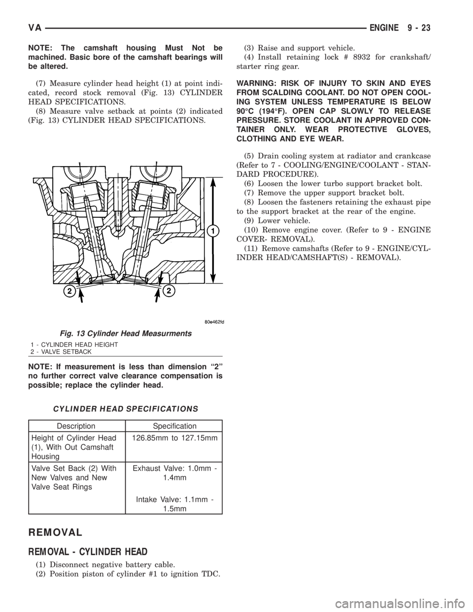
(7) Measure cylinder head height (1) at point indi-
cated, record stock removal (Fig. 13) CYLINDER
HEAD SPECIFICATIONS.
(8) Measure valve setback at points (2) indicated
(Fig. 13) CYLINDER HEAD SPECIFICATIONS.
NOTE: If measurement is less than dimension ª2º
no further correct valve clearance compensation is
possible; replace the cylinder head.
CYLINDER HEAD SPECIFICATIONS
Description Specification
Height of Cylinder Head
(1), With Out Camshaft
Housing126.85mm to 127.15mm
Valve Set Back (2) With
New Valves and New
Valve Seat RingsExhaust Valve: 1.0mm -
1.4mm
Intake Valve: 1.1mm -
1.5mm
REMOVAL
REMOVAL - CYLINDER HEAD
(1) Disconnect negative battery cable.
(2) Position piston of cylinder #1 to ignition TDC.(3) Raise and support vehicle.
(4) Install retaining lock # 8932 for crankshaft/
starter ring gear.
WARNING: RISK OF INJURY TO SKIN AND EYES
FROM SCALDING COOLANT. DO NOT OPEN COOL-
ING SYSTEM UNLESS TEMPERATURE IS BELOW
90ÉC (194ÉF). OPEN CAP SLOWLY TO RELEASE
PRESSURE. STORE COOLANT IN APPROVED CON-
TAINER ONLY. WEAR PROTECTIVE GLOVES,
CLOTHING AND EYE WEAR.
(5) Drain cooling system at radiator and crankcase
(Refer to 7 - COOLING/ENGINE/COOLANT - STAN-
DARD PROCEDURE).
(6) Loosen the lower turbo support bracket bolt.
(7) Remove the upper support bracket bolt.
(8) Loosen the fasteners retaining the exhaust pipe
to the support bracket at the rear of the engine.
(9) Lower vehicle.
(10) Remove engine cover. (Refer to 9 - ENGINE
COVER- REMOVAL).
(11) Remove camshafts (Refer to 9 - ENGINE/CYL-
INDER HEAD/CAMSHAFT(S) - REMOVAL).
Fig. 13 Cylinder Head Measurments
1 - CYLINDER HEAD HEIGHT
2 - VALVE SETBACK
VAENGINE 9 - 23
Page 1599 of 2305
(12) Remove the camshaft housing at the cylinder
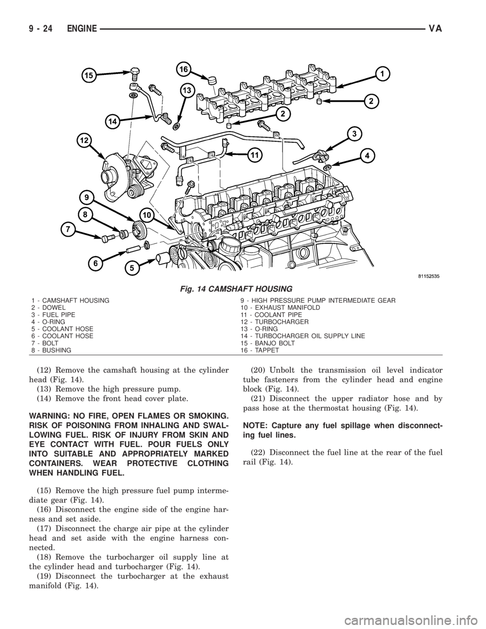
head (Fig. 14).
(13) Remove the high pressure pump.
(14) Remove the front head cover plate.
WARNING: NO FIRE, OPEN FLAMES OR SMOKING.
RISK OF POISONING FROM INHALING AND SWAL-
LOWING FUEL. RISK OF INJURY FROM SKIN AND
EYE CONTACT WITH FUEL. POUR FUELS ONLY
INTO SUITABLE AND APPROPRIATELY MARKED
CONTAINERS. WEAR PROTECTIVE CLOTHING
WHEN HANDLING FUEL.
(15) Remove the high pressure fuel pump interme-
diate gear (Fig. 14).
(16) Disconnect the engine side of the engine har-
ness and set aside.
(17) Disconnect the charge air pipe at the cylinder
head and set aside with the engine harness con-
nected.
(18) Remove the turbocharger oil supply line at
the cylinder head and turbocharger (Fig. 14).
(19) Disconnect the turbocharger at the exhaust
manifold (Fig. 14).(20) Unbolt the transmission oil level indicator
tube fasteners from the cylinder head and engine
block (Fig. 14).
(21) Disconnect the upper radiator hose and by
pass hose at the thermostat housing (Fig. 14).
NOTE: Capture any fuel spillage when disconnect-
ing fuel lines.
(22) Disconnect the fuel line at the rear of the fuel
rail (Fig. 14).
Fig. 14 CAMSHAFT HOUSING
1 - CAMSHAFT HOUSING 9 - HIGH PRESSURE PUMP INTERMEDIATE GEAR
2 - DOWEL 10 - EXHAUST MANIFOLD
3 - FUEL PIPE 11 - COOLANT PIPE
4 - O-RING 12 - TURBOCHARGER
5 - COOLANT HOSE 13 - O-RING
6 - COOLANT HOSE 14 - TURBOCHARGER OIL SUPPLY LINE
7 - BOLT 15 - BANJO BOLT
8 - BUSHING 16 - TAPPET
9 - 24 ENGINEVA
Page 1640 of 2305
REMOVAL
(1) Disconnect the negative battery cable.
(2) Raise and support the vehicle.
(3) Drain engine oil into a suitable, and appropri-
ately marked container.
(4) Remove engine mount to chassis nuts.
(5) Lower vehicle and install engine support.
(6) Remove the turbo charger heat shield to radia-
tor support bolts.
(7) Raise engine until the weight of the engine no
longer rests on the engine mounts.
(8) Raise and support the vehicle.
(9) Detach the front stabilizer bar at the front axle
and rotate it downward.
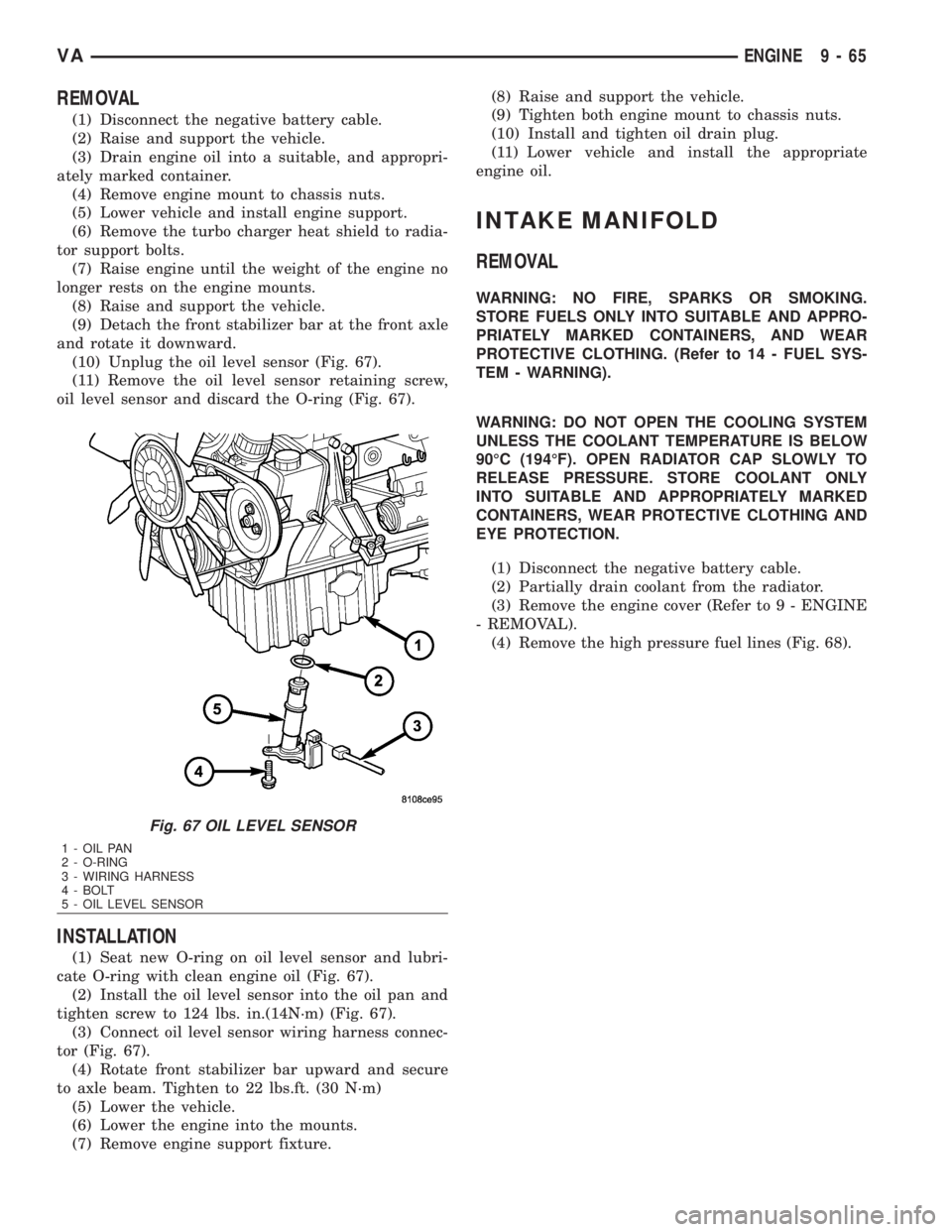
(10) Unplug the oil level sensor (Fig. 67).
(11) Remove the oil level sensor retaining screw,
oil level sensor and discard the O-ring (Fig. 67).
INSTALLATION
(1) Seat new O-ring on oil level sensor and lubri-
cate O-ring with clean engine oil (Fig. 67).
(2) Install the oil level sensor into the oil pan and
tighten screw to 124 lbs. in.(14N´m) (Fig. 67).
(3) Connect oil level sensor wiring harness connec-
tor (Fig. 67).
(4) Rotate front stabilizer bar upward and secure
to axle beam. Tighten to 22 lbs.ft. (30 N´m)
(5) Lower the vehicle.
(6) Lower the engine into the mounts.
(7) Remove engine support fixture.(8) Raise and support the vehicle.
(9) Tighten both engine mount to chassis nuts.
(10) Install and tighten oil drain plug.
(11) Lower vehicle and install the appropriate
engine oil.
INTAKE MANIFOLD
REMOVAL
WARNING: NO FIRE, SPARKS OR SMOKING.
STORE FUELS ONLY INTO SUITABLE AND APPRO-
PRIATELY MARKED CONTAINERS, AND WEAR
PROTECTIVE CLOTHING. (Refer to 14 - FUEL SYS-
TEM - WARNING).
WARNING: DO NOT OPEN THE COOLING SYSTEM
UNLESS THE COOLANT TEMPERATURE IS BELOW
90ÉC (194ÉF). OPEN RADIATOR CAP SLOWLY TO
RELEASE PRESSURE. STORE COOLANT ONLY
INTO SUITABLE AND APPROPRIATELY MARKED
CONTAINERS, WEAR PROTECTIVE CLOTHING AND
EYE PROTECTION.
(1) Disconnect the negative battery cable.
(2) Partially drain coolant from the radiator.
(3) Remove the engine cover (Refer to 9 - ENGINE
- REMOVAL).
(4) Remove the high pressure fuel lines (Fig. 68).
Fig. 67 OIL LEVEL SENSOR
1 - OIL PAN
2 - O-RING
3 - WIRING HARNESS
4 - BOLT
5 - OIL LEVEL SENSOR
VAENGINE 9 - 65
Page 1645 of 2305
(8) Install the exhaust hanger fasteners at the
muffler.
(9) Tighten the exhaust hanger bracket to engine
block.
(10) Install the turbocharger support bracket.
(11) Lower the vehicle.
(12) Install the air cleaner duct to the turbo-
charger (Fig. 71).
(13) Install the exhaust heat shield.
(14) Connect the negative battery cable.
TIMING CHAIN COVER
REMOVAL
WARNING: DO NOT OPEN COOLING SYSTEM
UNLESS TEMPERATURE IS BELOW 90ÉC (194ÉF).
OPEN CAP SLOWLY TO RELEASE PRESSURE.
STORE COOLANT IN APPROVED CONTAINER
ONLY. RISK OF INJURY TO SKIN AND EYES FROM
SCALDING COOLANT. WEAR PROTECTIVE
GLOVES, CLOTHING AND EYE WEAR.
(1) Disconnect negative battery cable.
NOTE: Rotate engine on crankshaft. DO NOT crank
the engine at the bolt of the camshaft sprocket.
NOTE: DO NOT crank engine back.
(2) Position piston of cylinder 1 to ignition TDC.
Markings on the camshaft bearing cap must be
aligned.
(3) Drain coolant (Refer to 7 - COOLING/ENGINE/
COOLANT - STANDARD PROCEDURE).
(4) Install retaining lock for crankshaft/starter
ring gear (Refer to 9 - ENGINE/ENGINE BLOCK/
FLEX PLATE - INSTALLATION).
(5) Drain engine oil.
(6) Remove the oil filter to allow the oil to flow off
into the oil pan.
(7) Remove the radiator assembly (Refer to 7 -
COOLING/ENGINE/RADIATOR - REMOVAL).
(8) Remove engine cover (Refer to 9 - ENGINE -
REMOVAL).
(9) Remove front cover at cylinder head (Refer to 9
- ENGINE/CYLINDER HEAD - REMOVAL).
(10) Remove accessory drive belt.
(11) Remove the high pressure fuel pump (Refer to
14 - FUEL SYSTEM/FUEL DELIVERY/FUEL PUMP
- REMOVAL).
(12) Remove water pump (Refer to 7 - COOLING/
ENGINE/WATER PUMP - REMOVAL).
(13) Remove accessory drive belt pulley and vibra-
tion damper (Refer to 9 - ENGINE/ENGINE BLOCK/
VIBRATION DAMPER - REMOVAL).
(14) Remove the power steering pump.NOTE: NO NOT open the air conditioning system.
(15) Unplug AC compressor electrical connector
and unbolt AC compressor. Relocate in lower engine
compartmentwith outopening the system.
(16) Remove the generator with wiring attached
and relocate somewhere in the engine compartment.
(17) Install engine support fixture.
(18) Remove the oil pan.
(19) Detach the coolant hose to oil-water heat
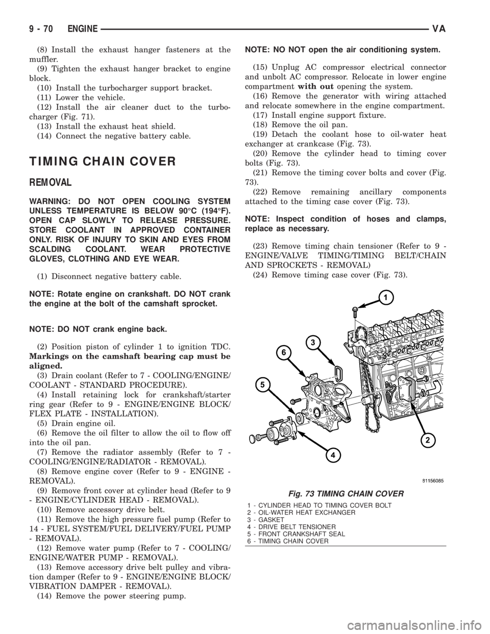
exchanger at crankcase (Fig. 73).
(20) Remove the cylinder head to timing cover
bolts (Fig. 73).
(21) Remove the timing cover bolts and cover (Fig.
73).
(22) Remove remaining ancillary components
attached to the timing case cover (Fig. 73).
NOTE: Inspect condition of hoses and clamps,
replace as necessary.
(23) Remove timing chain tensioner (Refer to 9 -
ENGINE/VALVE TIMING/TIMING BELT/CHAIN
AND SPROCKETS - REMOVAL)
(24) Remove timing case cover (Fig. 73).
Fig. 73 TIMING CHAIN COVER
1 - CYLINDER HEAD TO TIMING COVER BOLT
2 - OIL-WATER HEAT EXCHANGER
3 - GASKET
4 - DRIVE BELT TENSIONER
5 - FRONT CRANKSHAFT SEAL
6 - TIMING CHAIN COVER
9 - 70 ENGINEVA
Page 1646 of 2305
INSTALLATION
CAUTION: Care must be taken to closley inspect
the gasket area around the time case cover to cyl-
inder head gasket coolant port. If damage is found,
replace the cylinder head gasket. Failure to do so
may result in engine damage.
NOTE: Thoroughly clean all mating surfaces with
the appropriate solvents to assure that no grease or
oil is present during assembly.
(1) Inspect cylinder head gasket and oil pan gas-
ket. If damaged, replace.
(2) Replace the front crankshaft seal (Refer to 9 -
ENGINE/ENGINE BLOCK/CRANKSHAFT OIL
SEAL - FRONT - INSTALLATION).
(3) Install ancillary components to timing case
cover.
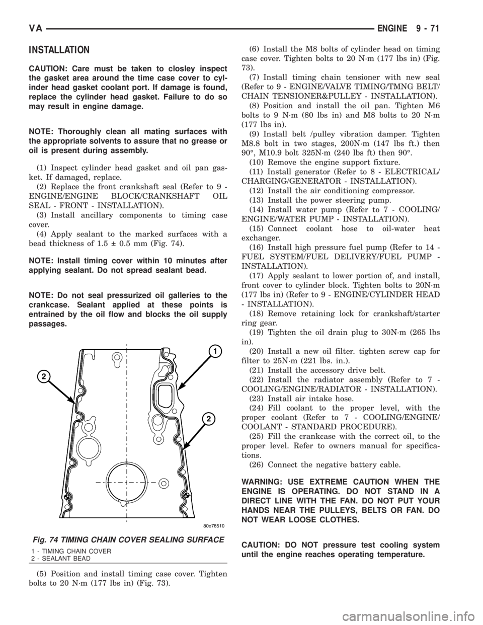
(4) Apply sealant to the marked surfaces with a
bead thickness of 1.5 0.5 mm (Fig. 74).
NOTE: Install timing cover within 10 minutes after
applying sealant. Do not spread sealant bead.
NOTE: Do not seal pressurized oil galleries to the
crankcase. Sealant applied at these points is
entrained by the oil flow and blocks the oil supply
passages.
(5) Position and install timing case cover. Tighten
bolts to 20 N´m (177 lbs in) (Fig. 73).(6) Install the M8 bolts of cylinder head on timing
case cover. Tighten bolts to 20 N´m (177 lbs in) (Fig.
73).
(7) Install timing chain tensioner with new seal
(Refer to 9 - ENGINE/VALVE TIMING/TMNG BELT/
CHAIN TENSIONER&PULLEY - INSTALLATION).
(8) Position and install the oil pan. Tighten M6
bolts to 9 N´m (80 lbs in) and M8 bolts to 20 N´m
(177 lbs in).
(9) Install belt /pulley vibration damper. Tighten
M8.8 bolt in two stages, 200N´m (147 lbs ft.) then
90É, M10.9 bolt 325N´m (240 lbs ft) then 90É.
(10) Remove the engine support fixture.
(11) Install generator (Refer to 8 - ELECTRICAL/
CHARGING/GENERATOR - INSTALLATION).
(12) Install the air conditioning compressor.
(13) Install the power steering pump.
(14) Install water pump (Refer to 7 - COOLING/
ENGINE/WATER PUMP - INSTALLATION).
(15) Connect coolant hose to oil-water heat
exchanger.
(16) Install high pressure fuel pump (Refer to 14 -
FUEL SYSTEM/FUEL DELIVERY/FUEL PUMP -
INSTALLATION).
(17) Apply sealant to lower portion of, and install,
front cover to cylinder block. Tighten bolts to 20N´m
(177 lbs in) (Refer to 9 - ENGINE/CYLINDER HEAD
- INSTALLATION).
(18) Remove retaining lock for crankshaft/starter
ring gear.
(19) Tighten the oil drain plug to 30N´m (265 lbs
in).
(20) Install a new oil filter. tighten screw cap for
filter to 25N´m (221 lbs. in.).
(21) Install the accessory drive belt.
(22) Install the radiator assembly (Refer to 7 -
COOLING/ENGINE/RADIATOR - INSTALLATION).
(23) Install air intake hose.
(24) Fill coolant to the proper level, with the
proper coolant (Refer to 7 - COOLING/ENGINE/
COOLANT - STANDARD PROCEDURE).
(25) Fill the crankcase with the correct oil, to the
proper level. Refer to owners manual for specifica-
tions.
(26) Connect the negative battery cable.
WARNING: USE EXTREME CAUTION WHEN THE
ENGINE IS OPERATING. DO NOT STAND IN A
DIRECT LINE WITH THE FAN. DO NOT PUT YOUR
HANDS NEAR THE PULLEYS, BELTS OR FAN. DO
NOT WEAR LOOSE CLOTHES.
CAUTION: DO NOT pressure test cooling system
until the engine reaches operating temperature.
Fig. 74 TIMING CHAIN COVER SEALING SURFACE
1 - TIMING CHAIN COVER
2 - SEALANT BEAD
VAENGINE 9 - 71
Page 1662 of 2305
OPERATION
Intake air is drawn through the air cleaner and
into the turbocharger compressor housing. Pressur-
ized air from the turbocharger then flows forward
through the charge air cooler located in front of the
radiator. From the charge air cooler the air flows
back into the intake manifold.
DIAGNOSIS AND TESTING - CHARGE AIR
COOLER SYSTEM - LEAKS
NOTE: Slight engine oil pooling in the charge air
inlet hose IS NOT premature turbocharger failure.
Slight pooling is the normal result of the breather
system. Test the air breather tube for normal oper-
ation by referring to the appropriate diagnostic
manual.
Low turbocharger boost pressure and low engine
performance can be caused by leaks in the charge air
cooler or it's plumbing. The following procedure out-
lines how to check for leaks in the charge air cooler
system.
(1) Loosen clamp and remove turbocharger to air
inlet duct rubber sleeve from turbocharger.
(2) Insert Special Tool 8442 Adapter into the rub-
ber sleeve. Tighten existing clamp to 8 N´m (72
in.lbs.).
CAUTION: Do not apply more than 138 kpa (20 psi)
air pressure to the charge air cooler system, sever
damage to the charge air cooler system may occur.
(3) Connect regulated air supply to air fitting on
Special Tool 8442 Adapter. Set air pressure to a Max-
imum of 138 kpa (20 psi).
(4) Using soapy water check the air inlet ducts,
rubber sleeves, charge air cooler and intake manifold
for leaks.
REMOVAL
(1) Remove front bumper.
(2) Remove headlamp assemblies.
(3) Remove front cross member together with front
grille.
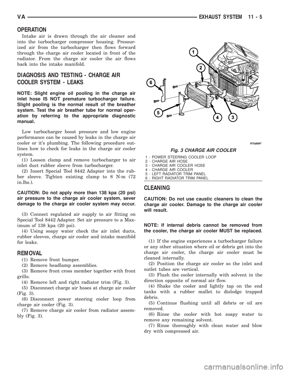
(4) Remove left and right radiator trim (Fig. 3).
(5) Disconnect charge air hoses at charge air cooler
(Fig. 3).
(6) Disconnect power steering cooler loop from
charge air cooler (Fig. 3).
(7) Remove charge air cooler from radiator assem-
bly (Fig. 3).
CLEANING
CAUTION: Do not use caustic cleaners to clean the
charge air cooler. Damage to the charge air cooler
will result.
NOTE: If internal debris cannot be removed from
the cooler, the charge air cooler MUST be replaced.
(1) If the engine experiences a turbocharger failure
or any other situation where oil or debris get into the
charge air cooler, the charge air cooler must be
cleaned internally.
(2) Position the charge air cooler so the inlet and
outlet tubes are vertical.
(3) Flush the cooler internally with solvent in the
direction opposite of normal air flow.
(4) Shake the cooler and lightly tap on the end
tanks with a rubber mallet to dislodge trapped
debris.
(5) Continue flushing until all debris or oil are
removed.
(6) Rinse the cooler with hot soapy water to
remove any remaining solvent.
(7) Rinse thoroughly with clean water and blow
dry with compressed air.
Fig. 3 CHARGE AIR COOLER
1 - POWER STEERING COOLER LOOP
2 - CHARGE AIR HOSE
3 - CHARGE AIR COOLER HOSE
4 - CHARGE AIR COOLER
5 - LEFT RADIATOR TRIM PANEL
6 - RIGHT RADIATOR TRIM PANEL
VAEXHAUST SYSTEM 11 - 5