2006 MERCEDES-BENZ SPRINTER radiator
[x] Cancel search: radiatorPage 1663 of 2305
INSPECTION
Visually inspect the charge air cooler for cracks,
holes, or damage. Inspect the tubes, fins, and welds
for tears, breaks, or other damage. Replace the
charge air cooler if damage is found.
Pressure test the charge air cooler, using Charge
Air Cooler Tester Kit.
INSTALLATION
(1) Install charge air cooler to radiator (Fig. 3).
(2) Connect power steering cooler loop to charge
air cooler (Fig. 3).
(3) Connect charge air hoses (Fig. 3).
(4) Install both radiator trim pieces (Fig. 3).
(5) Install front grille with front cross member.
(6) Install headlamp assemblies.
(7) Install front bumper.
TURBOCHARGER
DESCRIPTION
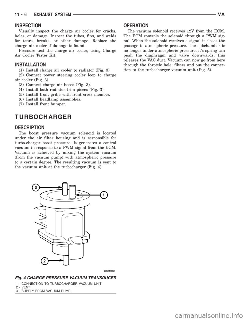
The boost pressure vacuum solenoid is located
under the air filter housing and is responsible for
turbo-charger boost pressure. It generates a control
vacuum in response to a PWM signal from the ECM.
Vacuum is achieved by mixing the system vacuum
(from the vacuum pump) with atmospheric pressure
to a certain degree. The resulting vacuum is sent to
the vacuum unit at the turbocharger (Fig. 4).
OPERATION
The vacuum solenoid receives 12V from the ECM.
The ECM controls the solenoid through a PWM sig-
nal. When the solenoid receives a signal it closes the
passage to atmospheric pressure. The subchamber is
no longer under atmospheric pressure, it's spring can
push the diaphragm and valve downwards; this
releases the VAC duct. Vacuum can now go from here
through the throttle hole, filters and out the connec-
tion to the turbocharger vacuum unit (Fig. 5).
Fig. 4 CHARGE PRESSURE VACUUM TRANSDUCER
1 - CONNECTION TO TURBOCHARGER VACUUM UNIT
2 - VENT
3 - SUPPLY FROM VACUUM PUMP
11 - 6 EXHAUST SYSTEMVA
Page 1742 of 2305
SPECIFICATIONS - TORQUE CHART
TORQUE SPECIFICATIONS
DESCRIPTION N´m Ft. Lbs. In. Lbs.
Power Steering Pump To
Timing Case Cover/Sup-
port21 15 185
High Pressure Flexible
Hose To Power Steering
Pump38 28 336
Power Steering Pulley To
Pump30 22 265
FLUID
STANDARD PROCEDURE
POWER STEERING PUMP FILL AND BLEED
PROCEDURE
(1) Remove the cap from the fluid reservoir.
Check cap seal for damage and replace if
needed.
(2) Fill the power steering pump with approved
fluid (Refer to LUBRICATION & MAINTENANCE/
FLUID TYPES - DESCRIPTION).Do not fill fluid
beyond the MAX mark.
(3) Raise the vehicles front wheels off the ground.
(4) With the engine off turn the steering wheel
from right to left.Perform this step until all the
bubble formations can no longer be seen in the
power steering reservoir.
(5) Start the engine and turn the steering wheel
with the engine at idle speed then shut the engine off
and check for correct oil level and no bubble in the
system.
(6) Reinstall power steering cap tightly.
(7) Test the system for leaks and proper operation.
FLUID COOLER TUBE
REMOVAL
(1) Siphon as much power steering fluid as possi-
ble out of the reservoir.
(2) Remove the grille (Refer to 23 - BODY/EXTE-
RIOR/GRILLE - REMOVAL).
(3) Remove the left headlight assembly.
(4) Disconnect the return lines from the cooler
tube.
(5) Remove the radiator clips (2).
(6) Remove the heat shield bolt for the turbo at
the core support.
(7) Remove the right headlight assembly.(8) Remove the core support bolts (4) and discon-
nect the hood latch cable.
(9) Remove the fan bracket bolts (4) to the radiator
(Fig. 2).
(10) Remove the two upper screws for the con-
denser (Fig. 2).
(11) Remove the condenser air dam shield.
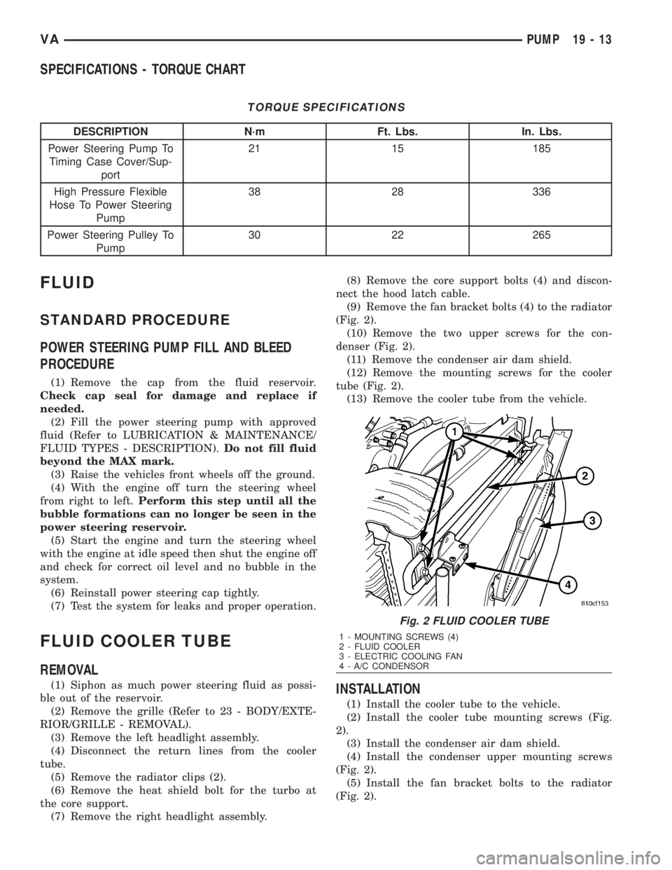
(12) Remove the mounting screws for the cooler
tube (Fig. 2).
(13) Remove the cooler tube from the vehicle.INSTALLATION
(1) Install the cooler tube to the vehicle.
(2) Install the cooler tube mounting screws (Fig.
2).
(3) Install the condenser air dam shield.
(4) Install the condenser upper mounting screws
(Fig. 2).
(5) Install the fan bracket bolts to the radiator
(Fig. 2).
Fig. 2 FLUID COOLER TUBE
1 - MOUNTING SCREWS (4)
2 - FLUID COOLER
3 - ELECTRIC COOLING FAN
4 - A/C CONDENSOR
VAPUMP 19 - 13
Page 1743 of 2305
(6) Install the core support bolts and reconnect the
hood latch cable.
(7) Install the right headlight assembly.
(8) Install the bolt for the turbo shield at the core
support.
(9) Install the radiator clips.
(10) Install the return lines to the cooler tube.
(11) Install the left headlight assembly.
(12) Install the grille assembly (Refer to 23 -
BODY/EXTERIOR/GRILLE - INSTALLATION).
(13) Fill the power steering fluid (Refer to 19 -
STEERING/PUMP/FLUID - STANDARD PROCE-
DURE).
HOSES
REMOVAL
REMOVAL - PRESSURE HOSE
(1) Siphon as much power steering fluid as possi-
ble out of the reservoir.
(2) Disconnect the pressure hose at the pump.
(3) Disconnect the pressure hose at the steering
gear.
(4) Remove the pressure hose mounting bracket
from the gear.
(5) Remove the pressure hose from the vehicle.
REMOVAL - RETURN LINE FROM PUMP TO
COOLER TUBE
(1) Siphon as much power steering fluid as possi-
ble out of the reservoir.
(2) Disconnect the return line at the pump.
(3) Remove the grille (Refer to 23 - BODY/EXTE-
RIOR/GRILLE - REMOVAL).
(4) Remove the left headlight assembly.
(5) Disconnect the return line at the cooler tube.
(6) Remove the return line from the vehicle.
REMOVAL - RETURN HOSE FROM GEAR TO
COOLER TUBE
(1) Siphon as much power steering fluid as possi-
ble out of the reservoir.
(2) Disconnect the return hose from the gear.
(3) Remove the grille (Refer to 23 - BODY/EXTE-
RIOR/GRILLE - REMOVAL).
(4) Remove the left headlight assembly.
(5) Disconnect the return line at the cooler tube.
(6) Remove the return line from the vehicle.
INSTALLATION
INSTALLATION - PRESSURE HOSE
(1) Install the pressure hose to the vehicle.(2) Reconnect the pressure hose at the steering
gear. Tighten to 37 N´m (27 ft.lbs.).
(3) Install the pressure hose mounting bracket to
the steering gear.
(4) Reconnect the pressure hose at the power
steering pump. Tighten to 38 N´m (28 ft.lbs.).
(5) Fill the power steering fluid (Refer to 19 -
STEERING/PUMP/FLUID - STANDARD PROCE-
DURE).
INSTALLATION - RETURN LINE FROM PUMP
TO COOLER TUBE
(1) Install the return line to the vehicle.
(2) Reconnect the return line at the cooler tube.
(3) Install the left headlight assembly.
(4) Install the grille assembly (Refer to 23 - BODY/
EXTERIOR/GRILLE - INSTALLATION).
(5) Reconnect the return line at the power steering
pump.
(6) Fill the power steering fluid (Refer to 19 -
STEERING/PUMP/FLUID - STANDARD PROCE-
DURE).
INSTALLATION - RETURN HOSE FROM GEAR
TO COOLER TUBE
(1) Install the return line to the vehicle.
(2) Reconnect the return line at the cooler tube.
(3) Install the left headlight assembly.
(4) Install the grille assembly (Refer to 23 - BODY/
EXTERIOR/GRILLE - INSTALLATION).
(5) Reconnect the return line at the power steering
gear.
(6) Fill the power steering fluid (Refer to 19 -
STEERING/PUMP/FLUID - STANDARD
PROCEDURE).
19 - 14 PUMPVA
Page 1875 of 2305
CAUSES OF BURNT FLUID
Burnt, discolored fluid is a result of overheating
which has three primary causes.
1. Internal clutch slippage, usually caused by low
line pressure, inadequate clutch apply pressure, or
clutch seal failure.
2. A result of restricted fluid flow through the
main and/or auxiliary cooler. This condition is usu-
ally the result of a faulty or improperly installed
drainback valve, a damaged oil cooler, or severe
restrictions in the coolers and lines caused by debris
or kinked lines.
3. Heavy duty operation with a vehicle not prop-
erly equipped for this type of operation. Trailer tow-
ing or similar high load operation will overheat the
transmission fluid if the vehicle is improperly
equipped. Such vehicles should have an auxiliary
transmission fluid cooler, a heavy duty cooling sys-
tem, and the engine/axle ratio combination needed to
handle heavy loads.
FLUID CONTAMINATION
Transmission fluid contamination is generally a
result of:
²adding incorrect fluid
²failure to clean dipstick and fill tube when
checking level
²engine coolant entering the fluid
²internal failure that generates debris
²overheat that generates sludge (fluid break-
down)
²failure to replace contaminated converter after
repair
The use of non-recommended fluids can result in
transmission failure. The usual results are erratic
shifts, slippage, abnormal wear and eventual failure
due to fluid breakdown and sludge formation. Avoid
this condition by using recommended fluids only.
The dipstick cap and fill tube should be wiped
clean before checking fluid level. Dirt, grease and
other foreign material on the cap and tube could fall
into the tube if not removed beforehand. Take the
time to wipe the cap and tube clean before withdraw-
ing the dipstick.
Engine coolant in the transmission fluid is gener-
ally caused by a cooler malfunction. The only remedy
is to replace the radiator as the cooler in the radiator
is not a serviceable part. If coolant has circulated
through the transmission, an overhaul is necessary.
The torque converter should be replaced whenever
a failure generates sludge and debris. This is neces-
sary because normal converter flushing procedures
will not remove all contaminants.
STANDARD PROCEDURE
CHECK OIL LEVEL
(1) Verify that the vehicle is parked on a level sur-
face.
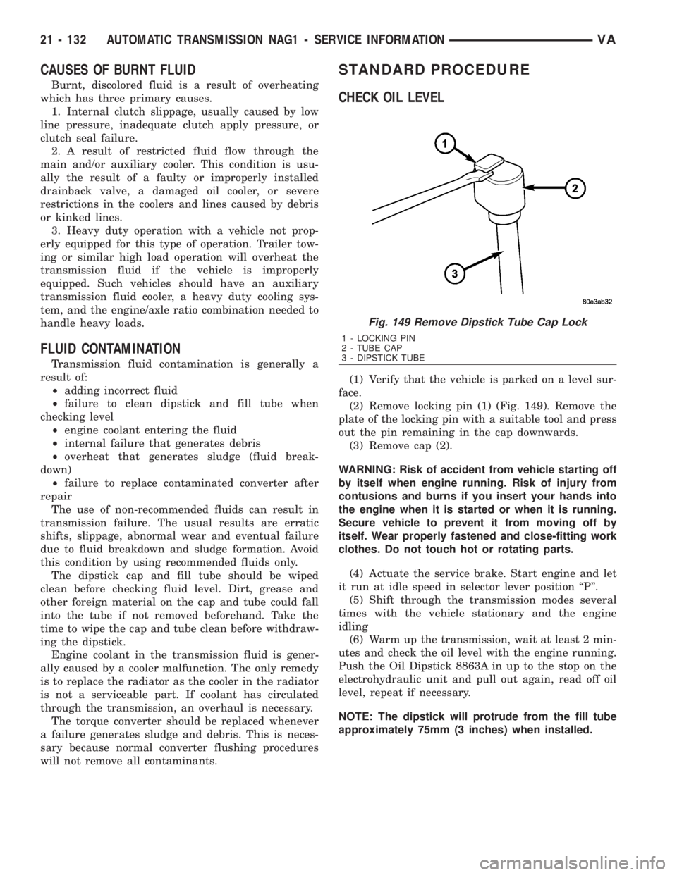
(2) Remove locking pin (1) (Fig. 149). Remove the
plate of the locking pin with a suitable tool and press
out the pin remaining in the cap downwards.
(3) Remove cap (2).
WARNING: Risk of accident from vehicle starting off
by itself when engine running. Risk of injury from
contusions and burns if you insert your hands into
the engine when it is started or when it is running.
Secure vehicle to prevent it from moving off by
itself. Wear properly fastened and close-fitting work
clothes. Do not touch hot or rotating parts.
(4) Actuate the service brake. Start engine and let
it run at idle speed in selector lever position ªPº.
(5) Shift through the transmission modes several
times with the vehicle stationary and the engine
idling
(6) Warm up the transmission, wait at least 2 min-
utes and check the oil level with the engine running.
Push the Oil Dipstick 8863A in up to the stop on the
electrohydraulic unit and pull out again, read off oil
level, repeat if necessary.
NOTE: The dipstick will protrude from the fill tube
approximately 75mm (3 inches) when installed.
Fig. 149 Remove Dipstick Tube Cap Lock
1 - LOCKING PIN
2 - TUBE CAP
3 - DIPSTICK TUBE
21 - 132 AUTOMATIC TRANSMISSION NAG1 - SERVICE INFORMATIONVA
Page 1955 of 2305
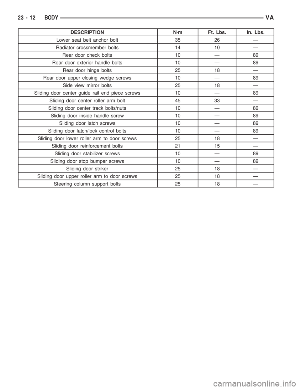
DESCRIPTION N´m Ft. Lbs. In. Lbs.
Lower seat belt anchor bolt 35 26 Ð
Radiator crossmember bolts 14 10 Ð
Rear door check bolts 10 Ð 89
Rear door exterior handle bolts 10 Ð 89
Rear door hinge bolts 25 18 Ð
Rear door upper closing wedge screws 10 Ð 89
Side view mirror bolts 25 18 Ð
Sliding door center guide rail end piece screws 10 Ð 89
Sliding door center roller arm bolt 45 33 Ð
Sliding door center track bolts/nuts 10 Ð 89
Sliding door inside handle screw 10 Ð 89
Sliding door latch screws 10 Ð 89
Sliding door latch/lock control bolts 10 Ð 89
Sliding door lower roller arm to door screws 25 18 Ð
Sliding door reinforcement bolts 21 15 Ð
Sliding door stabilizer screws 10 Ð 89
Sliding door stop bumper screws 10 Ð 89
Sliding door striker 25 18 Ð
Sliding door upper roller arm to door screws 25 18 Ð
Steering column support bolts 25 18 Ð
23 - 12 BODYVA
Page 1991 of 2305
EXTERIOR
TABLE OF CONTENTS
page page
FUEL FILL DOOR
REMOVAL.............................48
INSTALLATION.........................48
GRILLE
REMOVAL.............................48
INSTALLATION.........................48
LICENSE PLATE BRACKET
REMOVAL.............................48
INSTALLATION.........................48RADIATOR CROSSMEMBER
REMOVAL.............................49
INSTALLATION.........................49
SIDE VIEW MIRROR
REMOVAL.............................49
INSTALLATION.........................50
SIDE VIEW MIRROR - GLASS
REMOVAL.............................50
INSTALLATION.........................50
FUEL FILL DOOR
REMOVAL
(1) Open passenger compartment door.
(2) Open fuel fill door.
(3) Using a trim stick C-4755 or equivalent, dis-
connect the filler cap tether.
(4) Remove two bolts and remove filler door.
INSTALLATION
(1) Install the door and bolts.
(2) Connect filler cap tether.
(3) Close doors.
GRILLE
REMOVAL
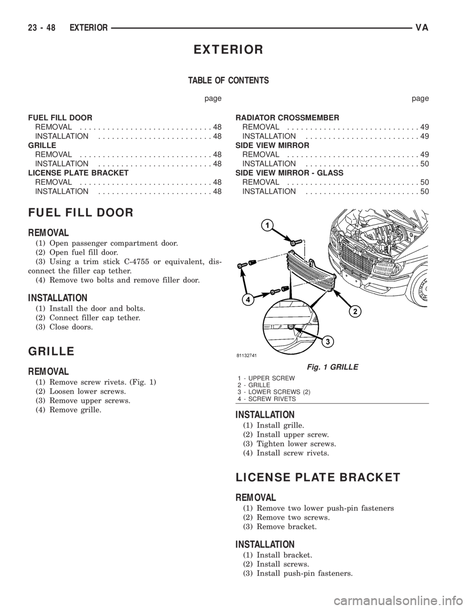
(1) Remove screw rivets. (Fig. 1)
(2) Loosen lower screws.
(3) Remove upper screws.
(4) Remove grille.
INSTALLATION
(1) Install grille.
(2) Install upper screw.
(3) Tighten lower screws.
(4) Install screw rivets.
LICENSE PLATE BRACKET
REMOVAL
(1) Remove two lower push-pin fasteners
(2) Remove two screws.
(3) Remove bracket.
INSTALLATION
(1) Install bracket.
(2) Install screws.
(3) Install push-pin fasteners.
Fig. 1 GRILLE
1 - UPPER SCREW
2 - GRILLE
3 - LOWER SCREWS (2)
4 - SCREW RIVETS
23 - 48 EXTERIORVA
Page 1992 of 2305
RADIATOR CROSSMEMBER
REMOVAL
(1) Remove grille. (Refer to 23 - BODY/EXTERI-
OR/GRILLE - REMOVAL)
(2) Remove headlamps. (Refer to 8 - ELECTRI-
CAL/LAMPS/LIGHTING - EXTERIOR/FRONT
LAMP UNIT - REMOVAL)
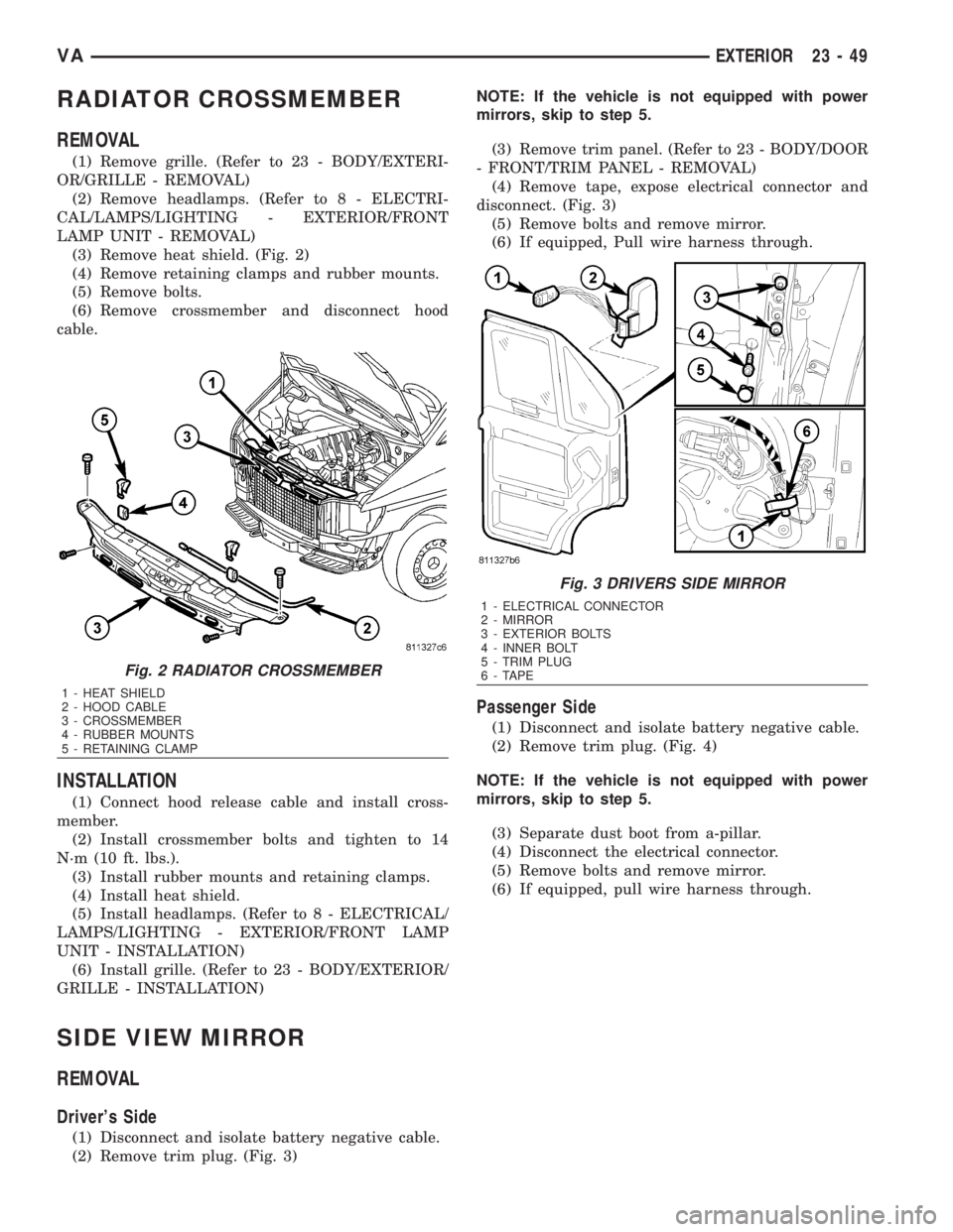
(3) Remove heat shield. (Fig. 2)
(4) Remove retaining clamps and rubber mounts.
(5) Remove bolts.
(6) Remove crossmember and disconnect hood
cable.
INSTALLATION
(1) Connect hood release cable and install cross-
member.
(2) Install crossmember bolts and tighten to 14
N´m (10 ft. lbs.).
(3) Install rubber mounts and retaining clamps.
(4) Install heat shield.
(5) Install headlamps. (Refer to 8 - ELECTRICAL/
LAMPS/LIGHTING - EXTERIOR/FRONT LAMP
UNIT - INSTALLATION)
(6) Install grille. (Refer to 23 - BODY/EXTERIOR/
GRILLE - INSTALLATION)
SIDE VIEW MIRROR
REMOVAL
Driver's Side
(1) Disconnect and isolate battery negative cable.
(2) Remove trim plug. (Fig. 3)NOTE: If the vehicle is not equipped with power
mirrors, skip to step 5.
(3) Remove trim panel. (Refer to 23 - BODY/DOOR
- FRONT/TRIM PANEL - REMOVAL)
(4) Remove tape, expose electrical connector and
disconnect. (Fig. 3)
(5) Remove bolts and remove mirror.
(6) If equipped, Pull wire harness through.
Passenger Side
(1) Disconnect and isolate battery negative cable.
(2) Remove trim plug. (Fig. 4)
NOTE: If the vehicle is not equipped with power
mirrors, skip to step 5.
(3) Separate dust boot from a-pillar.
(4) Disconnect the electrical connector.
(5) Remove bolts and remove mirror.
(6) If equipped, pull wire harness through.
Fig. 2 RADIATOR CROSSMEMBER
1 - HEAT SHIELD
2 - HOOD CABLE
3 - CROSSMEMBER
4 - RUBBER MOUNTS
5 - RETAINING CLAMP
Fig. 3 DRIVERS SIDE MIRROR
1 - ELECTRICAL CONNECTOR
2 - MIRROR
3 - EXTERIOR BOLTS
4 - INNER BOLT
5 - TRIM PLUG
6 - TAPE
VAEXTERIOR 23 - 49
Page 2038 of 2305
HEATING & AIR CONDITIONING
TABLE OF CONTENTS
page page
HEATING & AIR CONDITIONING
DESCRIPTION..........................1
OPERATION............................2
DIAGNOSIS AND TESTING
A/C PERFORMANCE....................3
HEATER PERFORMANCE TEST...........5
ATC FUNCTION TEST...................6
SPECIFICATIONS
HEATING-A/C SYSTEM..................6CONTROLS-FRONT........................8
CONTROLS - REAR......................24
DISTRIBUTION - FRONT...................45
DISTRIBUTION - REAR....................52
PLUMBING.............................60
CABIN HEATER.........................104
HEATING & AIR CONDITION-
ING
DESCRIPTION
An automatic temperature control (ATC) single
zone type heating-A/C system is standard equipment
on this model.
To maintain the performance level of the heating,
ventilation and air conditioning (HVAC) system, the
engine cooling system must be properly maintained.
The use of a bug screen is not recommended. Any
obstructions in front of the radiator or A/C condenser
will reduce the performance of the A/C and engine
cooling systems.
The engine cooling system includes the radiator,
thermostat, radiator hoses and the engine coolant
pump. Refer to 7 - Cooling for more information
before opening or attempting any service to the
engine cooling system.
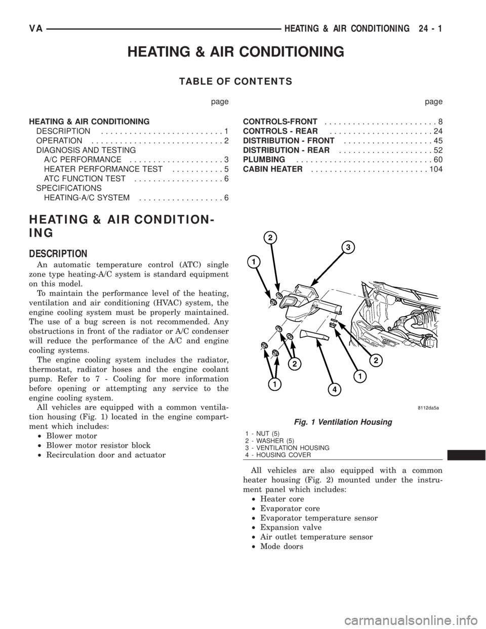
All vehicles are equipped with a common ventila-
tion housing (Fig. 1) located in the engine compart-
ment which includes:
²Blower motor
²Blower motor resistor block
²Recirculation door and actuator
All vehicles are also equipped with a common
heater housing (Fig. 2) mounted under the instru-
ment panel which includes:
²Heater core
²Evaporator core
²Evaporator temperature sensor
²Expansion valve
²Air outlet temperature sensor
²Mode doors
Fig. 1 Ventilation Housing
1 - NUT (5)
2 - WASHER (5)
3 - VENTILATION HOUSING
4 - HOUSING COVER
VAHEATING & AIR CONDITIONING 24 - 1