Page 2141 of 2305
CABIN HEATER
TABLE OF CONTENTS
page page
CABIN HEATER
DESCRIPTION........................104
OPERATION..........................104
DIAGNOSIS AND TESTING
SUPPLEMENTAL CABIN HEATER........104
EXHAUST TUBE
REMOVAL............................105
INSTALLATION........................106
FUEL DOSING PUMP
DESCRIPTION........................106
OPERATION..........................106
REMOVAL............................106
INSTALLATION........................107
FUEL LINE
STANDARD PROCEDURE
CLEANING.........................107REMOVAL............................108
INSTALLATION........................109
HEATER UNIT
REMOVAL
HEATER UNIT.......................110
WIRE HARNESS.....................110
INSTALLATION
HEATER UNIT.......................110
WIRE HARNESS.....................111
INLET HOSE
REMOVAL............................111
INSTALLATION........................112
CABIN HEATER
DESCRIPTION
Vehicles equipped with the diesel engine are also
equipped with a supplemental cabin heater. This
cabin heater is mounted under the vehicle and oper-
ates similar to an oil fired furnace. The heater burns
small amounts of fuel to provide additional heat to
the coolant. Coolant is routed from the engine, to the
supplemental cabin heater and then to the front
heater core. This provides additional heat to the pas-
senger compartment. The supplemental cabin heater
system is interfaced to the vehicles on-board com-
puter systems and DRBIIItdiagnostics.
The supplemental cabin heater has an electronic
control module that monitors the heat output of the
heater. The cabin heater operates at full load (5 kW),
half load or idle mode (no additional heat) depending
on engine coolant temperature.
OPERATION
The supplemental cabin heater is activated by
using the temperature control on the A/C-heater con-
trol. The supplemental cabin heater is activated
when the temperature control is set to/or above the
upper set point. The supplemental cabin heater can
operate in a full or partial load range as well as an
idle mode, all dependent on the engine coolant tem-
perature. The heater unit will also turn off if the
temperature control is set to less than the lower set
point. The supplemental cabin heater can take up to
three minutes to completely shut down when eitherthe heater temperature is set below the lower set
point or the vehicle ignition is turned off.
The supplemental cabin heater only operates when
the engine is running, the mileage exceeds 8 kilome-
ter (5 mph) and the fuel tank volume exceeds 1/8 of a
tank. The heater should start if the coolant temper-
ature is below 40É C (104É F).
NOTE: Do not apply a strong vacuum directly on
the supplemental cabin heater exhaust line. Place
the vacuum within 75 mm (3 inches) of the exhaust
port. Too strong of a vacuum can prevent the heater
from starting. The heater control module monitors
the blower speed and combustion during its start-
up.
DIAGNOSIS AND TESTING
SUPPLEMENTAL CABIN HEATER
Refer to the Symptoms Diagnosis table for basic
checks of the diesel fueled supplemental cabin heater.
24 - 104 CABIN HEATERVA
Page 2143 of 2305
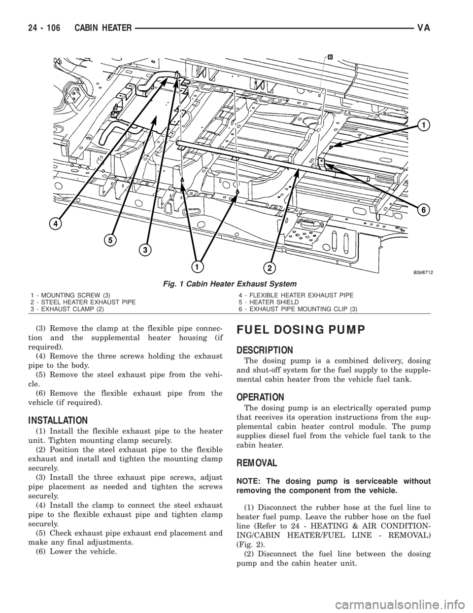
(3) Remove the clamp at the flexible pipe connec-
tion and the supplemental heater housing (if
required).
(4) Remove the three screws holding the exhaust
pipe to the body.
(5) Remove the steel exhaust pipe from the vehi-
cle.
(6) Remove the flexible exhaust pipe from the
vehicle (if required).
INSTALLATION
(1) Install the flexible exhaust pipe to the heater
unit. Tighten mounting clamp securely.
(2) Position the steel exhaust pipe to the flexible
exhaust and install and tighten the mounting clamp
securely.
(3) Install the three exhaust pipe screws, adjust
pipe placement as needed and tighten the screws
securely.
(4) Install the clamp to connect the steel exhaust
pipe to the flexible exhaust pipe and tighten clamp
securely.
(5) Check exhaust pipe exhaust end placement and
make any final adjustments.
(6) Lower the vehicle.
FUEL DOSING PUMP
DESCRIPTION
The dosing pump is a combined delivery, dosing
and shut-off system for the fuel supply to the supple-
mental cabin heater from the vehicle fuel tank.
OPERATION
The dosing pump is an electrically operated pump
that receives its operation instructions from the sup-
plemental cabin heater control module. The pump
supplies diesel fuel from the vehicle fuel tank to the
cabin heater.
REMOVAL
NOTE: The dosing pump is serviceable without
removing the component from the vehicle.
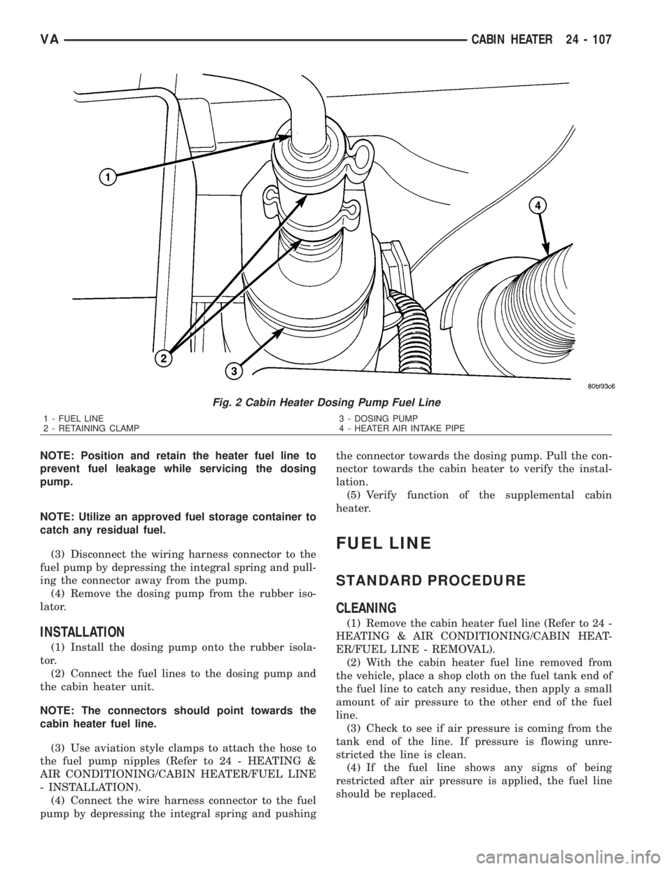
(1) Disconnect the rubber hose at the fuel line to
heater fuel pump. Leave the rubber hose on the fuel
line (Refer to 24 - HEATING & AIR CONDITION-
ING/CABIN HEATER/FUEL LINE - REMOVAL)
(Fig. 2).
(2) Disconnect the fuel line between the dosing
pump and the cabin heater unit.
Fig. 1 Cabin Heater Exhaust System
1 - MOUNTING SCREW (3)
2 - STEEL HEATER EXHAUST PIPE
3 - EXHAUST CLAMP (2)4 - FLEXIBLE HEATER EXHAUST PIPE
5 - HEATER SHIELD
6 - EXHAUST PIPE MOUNTING CLIP (3)
24 - 106 CABIN HEATERVA
Page 2144 of 2305
NOTE: Position and retain the heater fuel line to
prevent fuel leakage while servicing the dosing
pump.
NOTE: Utilize an approved fuel storage container to
catch any residual fuel.
(3) Disconnect the wiring harness connector to the
fuel pump by depressing the integral spring and pull-
ing the connector away from the pump.
(4) Remove the dosing pump from the rubber iso-
lator.
INSTALLATION
(1) Install the dosing pump onto the rubber isola-
tor.
(2) Connect the fuel lines to the dosing pump and
the cabin heater unit.
NOTE: The connectors should point towards the
cabin heater fuel line.
(3) Use aviation style clamps to attach the hose to
the fuel pump nipples (Refer to 24 - HEATING &
AIR CONDITIONING/CABIN HEATER/FUEL LINE
- INSTALLATION).
(4) Connect the wire harness connector to the fuel
pump by depressing the integral spring and pushingthe connector towards the dosing pump. Pull the con-
nector towards the cabin heater to verify the instal-
lation.
(5) Verify function of the supplemental cabin
heater.
FUEL LINE
STANDARD PROCEDURE
CLEANING
(1) Remove the cabin heater fuel line (Refer to 24 -
HEATING & AIR CONDITIONING/CABIN HEAT-
ER/FUEL LINE - REMOVAL).
(2) With the cabin heater fuel line removed from
the vehicle, place a shop cloth on the fuel tank end of
the fuel line to catch any residue, then apply a small
amount of air pressure to the other end of the fuel
line.
(3) Check to see if air pressure is coming from the
tank end of the line. If pressure is flowing unre-
stricted the line is clean.
(4) If the fuel line shows any signs of being
restricted after air pressure is applied, the fuel line
should be replaced.
Fig. 2 Cabin Heater Dosing Pump Fuel Line
1 - FUEL LINE
2 - RETAINING CLAMP3 - DOSING PUMP
4 - HEATER AIR INTAKE PIPE
VACABIN HEATER 24 - 107
Page:
< prev 1-8 9-16 17-24