2006 MERCEDES-BENZ SPRINTER fuel filter
[x] Cancel search: fuel filterPage 1589 of 2305
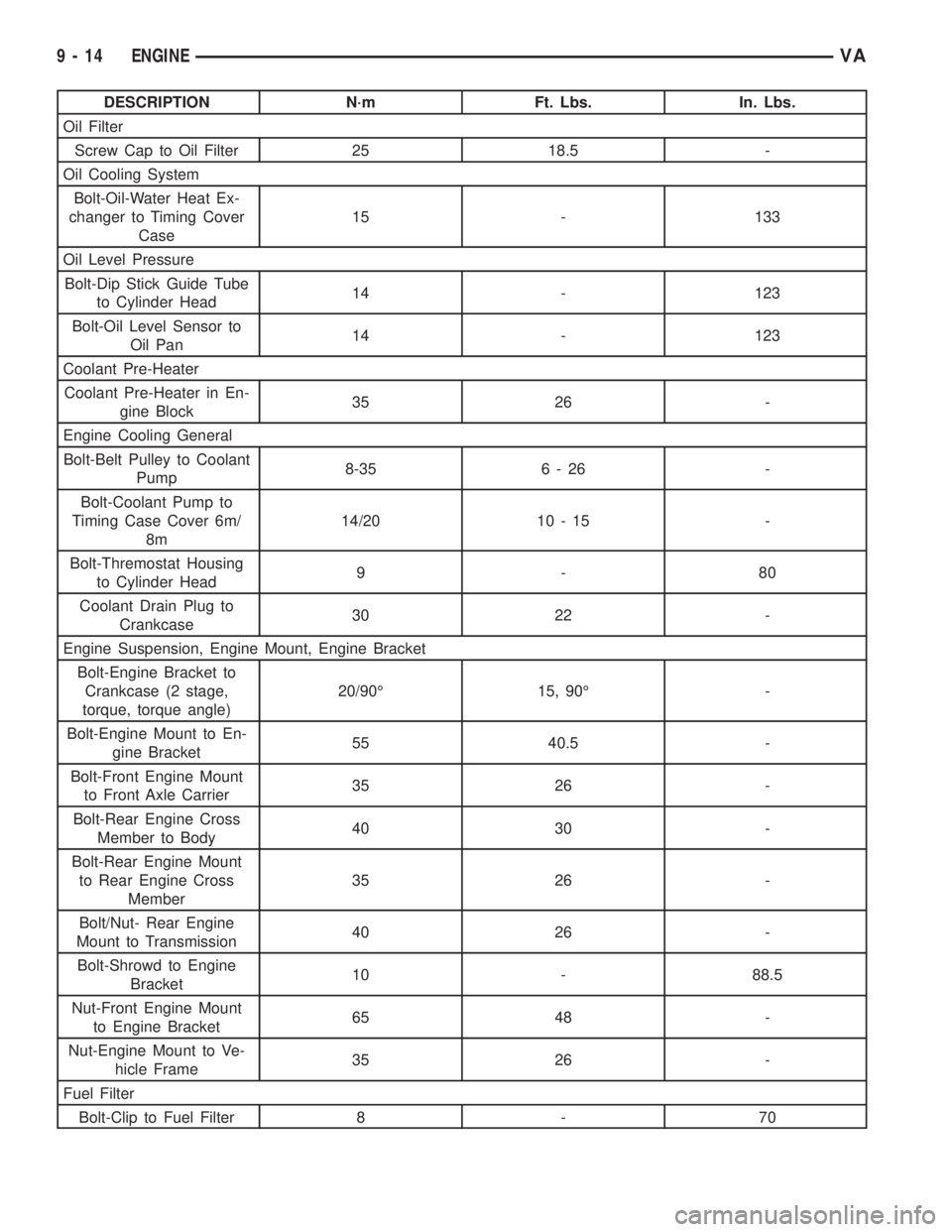
DESCRIPTION N´m Ft. Lbs. In. Lbs.
Oil Filter
Screw Cap to Oil Filter 25 18.5 -
Oil Cooling System
Bolt-Oil-Water Heat Ex-
changer to Timing Cover
Case15 - 133
Oil Level Pressure
Bolt-Dip Stick Guide Tube
to Cylinder Head14 - 123
Bolt-Oil Level Sensor to
Oil Pan14 - 123
Coolant Pre-Heater
Coolant Pre-Heater in En-
gine Block35 26 -
Engine Cooling General
Bolt-Belt Pulley to Coolant
Pump8-35 6 - 26 -
Bolt-Coolant Pump to
Timing Case Cover 6m/
8m14/20 10 - 15 -
Bolt-Thremostat Housing
to Cylinder Head9-80
Coolant Drain Plug to
Crankcase30 22 -
Engine Suspension, Engine Mount, Engine Bracket
Bolt-Engine Bracket to
Crankcase (2 stage,
torque, torque angle)20/90É 15, 90É -
Bolt-Engine Mount to En-
gine Bracket55 40.5 -
Bolt-Front Engine Mount
to Front Axle Carrier35 26 -
Bolt-Rear Engine Cross
Member to Body40 30 -
Bolt-Rear Engine Mount
to Rear Engine Cross
Member35 26 -
Bolt/Nut- Rear Engine
Mount to Transmission40 26 -
Bolt-Shrowd to Engine
Bracket10 - 88.5
Nut-Front Engine Mount
to Engine Bracket65 48 -
Nut-Engine Mount to Ve-
hicle Frame35 26 -
Fuel Filter
Bolt-Clip to Fuel Filter 8 - 70
9 - 14 ENGINEVA
Page 1590 of 2305
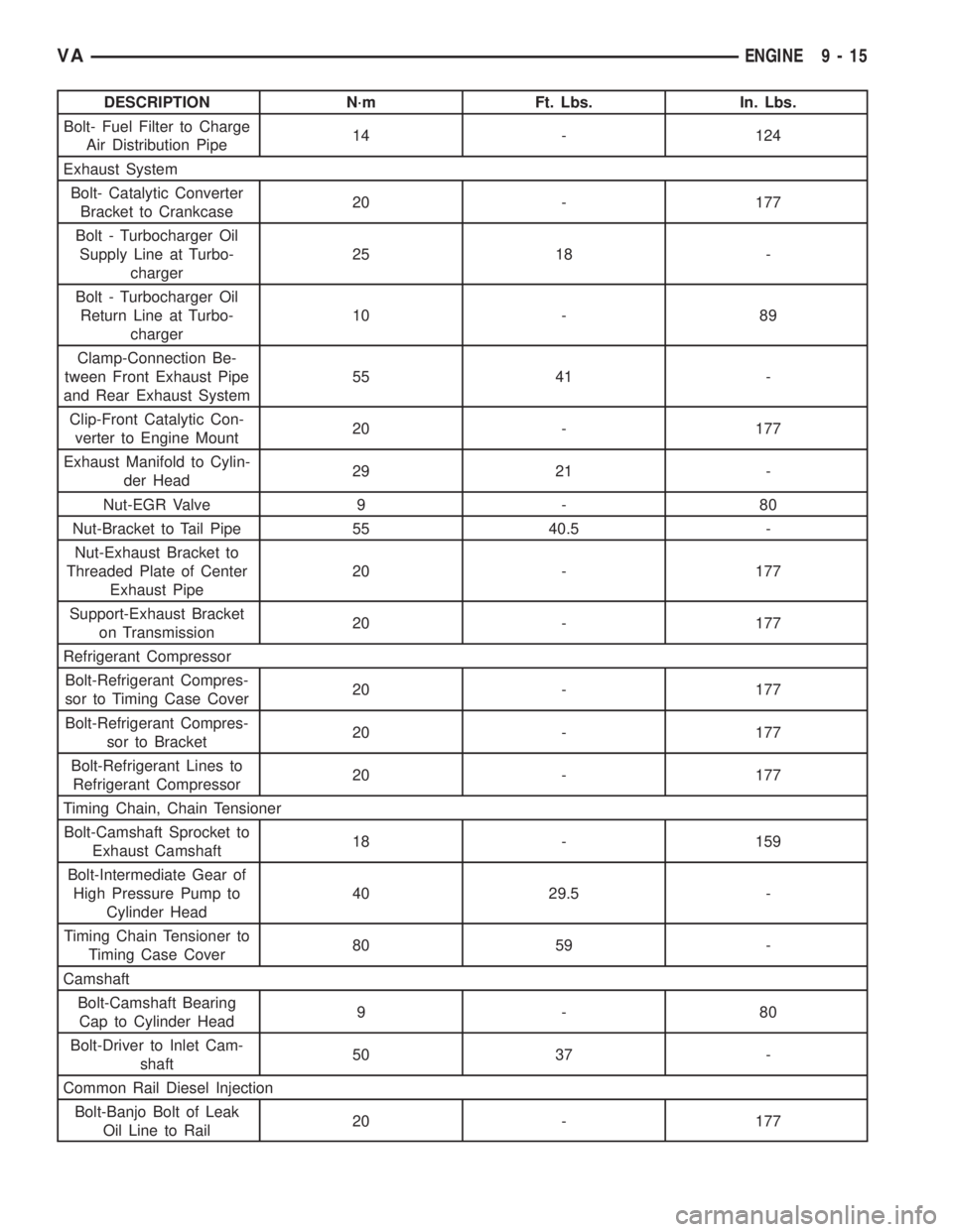
DESCRIPTION N´m Ft. Lbs. In. Lbs.
Bolt- Fuel Filter to Charge
Air Distribution Pipe14 - 124
Exhaust System
Bolt- Catalytic Converter
Bracket to Crankcase20 - 177
Bolt - Turbocharger Oil
Supply Line at Turbo-
charger25 18 -
Bolt - Turbocharger Oil
Return Line at Turbo-
charger10 - 89
Clamp-Connection Be-
tween Front Exhaust Pipe
and Rear Exhaust System55 41 -
Clip-Front Catalytic Con-
verter to Engine Mount20 - 177
Exhaust Manifold to Cylin-
der Head29 21 -
Nut-EGR Valve 9 - 80
Nut-Bracket to Tail Pipe 55 40.5 -
Nut-Exhaust Bracket to
Threaded Plate of Center
Exhaust Pipe20 - 177
Support-Exhaust Bracket
on Transmission20 - 177
Refrigerant Compressor
Bolt-Refrigerant Compres-
sor to Timing Case Cover20 - 177
Bolt-Refrigerant Compres-
sor to Bracket20 - 177
Bolt-Refrigerant Lines to
Refrigerant Compressor20 - 177
Timing Chain, Chain Tensioner
Bolt-Camshaft Sprocket to
Exhaust Camshaft18 - 159
Bolt-Intermediate Gear of
High Pressure Pump to
Cylinder Head40 29.5 -
Timing Chain Tensioner to
Timing Case Cover80 59 -
Camshaft
Bolt-Camshaft Bearing
Cap to Cylinder Head9-80
Bolt-Driver to Inlet Cam-
shaft50 37 -
Common Rail Diesel Injection
Bolt-Banjo Bolt of Leak
Oil Line to Rail20 - 177
VAENGINE 9 - 15
Page 1642 of 2305
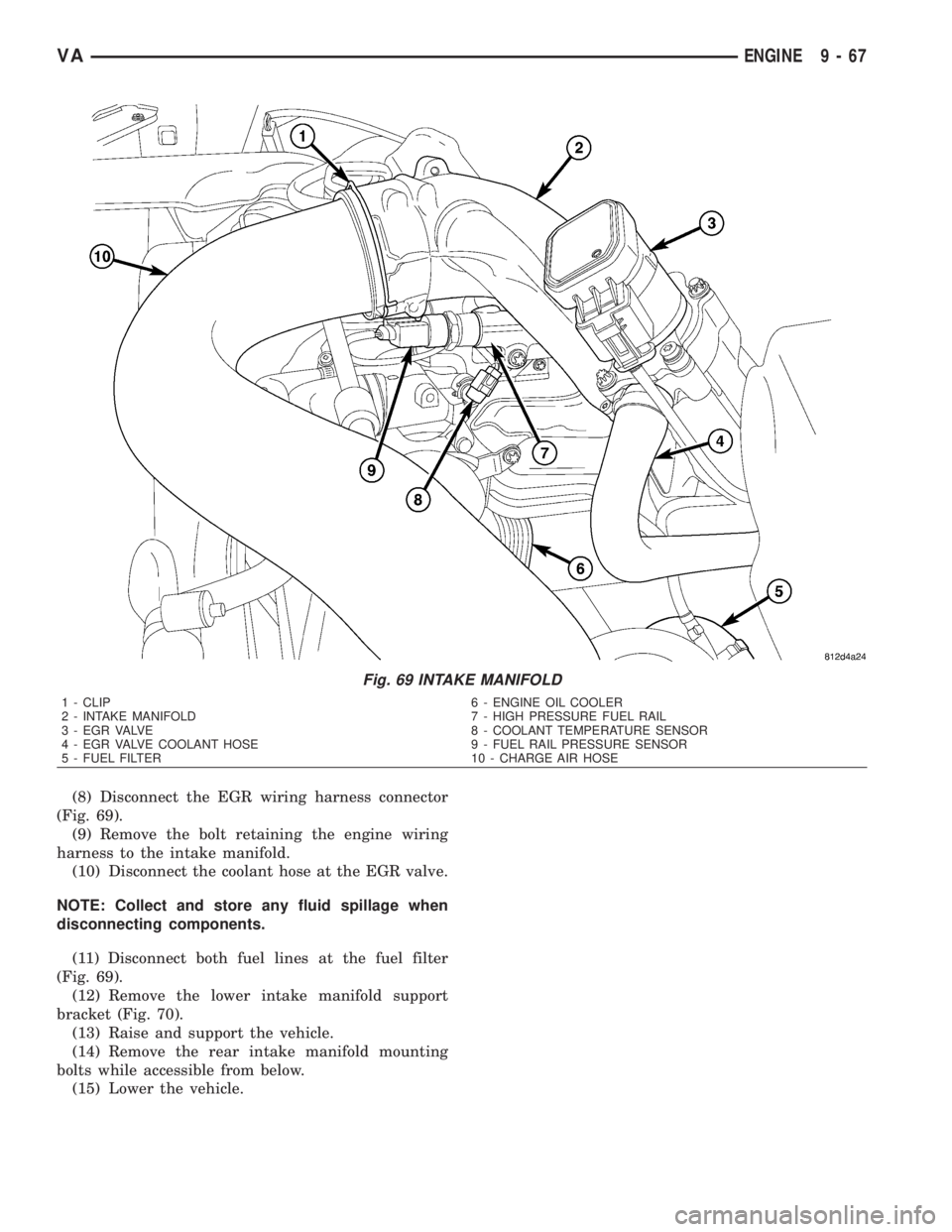
(8) Disconnect the EGR wiring harness connector
(Fig. 69).
(9) Remove the bolt retaining the engine wiring
harness to the intake manifold.
(10) Disconnect the coolant hose at the EGR valve.
NOTE: Collect and store any fluid spillage when
disconnecting components.
(11) Disconnect both fuel lines at the fuel filter
(Fig. 69).
(12) Remove the lower intake manifold support
bracket (Fig. 70).
(13) Raise and support the vehicle.
(14) Remove the rear intake manifold mounting
bolts while accessible from below.
(15) Lower the vehicle.
Fig. 69 INTAKE MANIFOLD
1 - CLIP 6 - ENGINE OIL COOLER
2 - INTAKE MANIFOLD 7 - HIGH PRESSURE FUEL RAIL
3 - EGR VALVE 8 - COOLANT TEMPERATURE SENSOR
4 - EGR VALVE COOLANT HOSE 9 - FUEL RAIL PRESSURE SENSOR
5 - FUEL FILTER 10 - CHARGE AIR HOSE
VAENGINE 9 - 67
Page 1643 of 2305
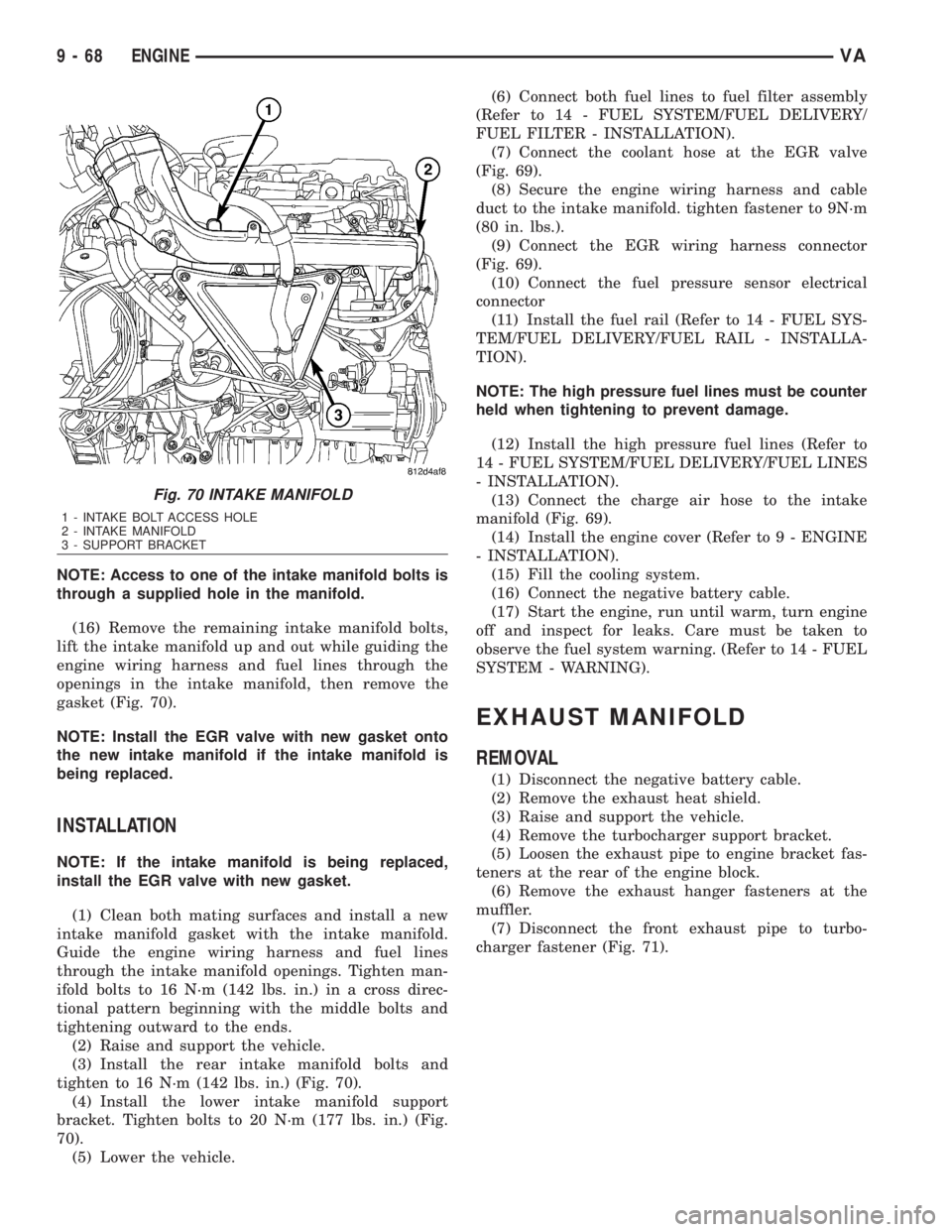
NOTE: Access to one of the intake manifold bolts is
through a supplied hole in the manifold.
(16) Remove the remaining intake manifold bolts,
lift the intake manifold up and out while guiding the
engine wiring harness and fuel lines through the
openings in the intake manifold, then remove the
gasket (Fig. 70).
NOTE: Install the EGR valve with new gasket onto
the new intake manifold if the intake manifold is
being replaced.
INSTALLATION
NOTE: If the intake manifold is being replaced,
install the EGR valve with new gasket.
(1) Clean both mating surfaces and install a new
intake manifold gasket with the intake manifold.
Guide the engine wiring harness and fuel lines
through the intake manifold openings. Tighten man-
ifold bolts to 16 N´m (142 lbs. in.) in a cross direc-
tional pattern beginning with the middle bolts and
tightening outward to the ends.
(2) Raise and support the vehicle.
(3) Install the rear intake manifold bolts and
tighten to 16 N´m (142 lbs. in.) (Fig. 70).
(4) Install the lower intake manifold support
bracket. Tighten bolts to 20 N´m (177 lbs. in.) (Fig.
70).
(5) Lower the vehicle.(6) Connect both fuel lines to fuel filter assembly
(Refer to 14 - FUEL SYSTEM/FUEL DELIVERY/
FUEL FILTER - INSTALLATION).
(7) Connect the coolant hose at the EGR valve
(Fig. 69).
(8) Secure the engine wiring harness and cable
duct to the intake manifold. tighten fastener to 9N´m
(80 in. lbs.).
(9) Connect the EGR wiring harness connector
(Fig. 69).
(10) Connect the fuel pressure sensor electrical
connector
(11) Install the fuel rail (Refer to 14 - FUEL SYS-
TEM/FUEL DELIVERY/FUEL RAIL - INSTALLA-
TION).
NOTE: The high pressure fuel lines must be counter
held when tightening to prevent damage.
(12) Install the high pressure fuel lines (Refer to
14 - FUEL SYSTEM/FUEL DELIVERY/FUEL LINES
- INSTALLATION).
(13) Connect the charge air hose to the intake
manifold (Fig. 69).
(14) Install the engine cover (Refer to 9 - ENGINE
- INSTALLATION).
(15) Fill the cooling system.
(16) Connect the negative battery cable.
(17) Start the engine, run until warm, turn engine
off and inspect for leaks. Care must be taken to
observe the fuel system warning. (Refer to 14 - FUEL
SYSTEM - WARNING).
EXHAUST MANIFOLD
REMOVAL
(1) Disconnect the negative battery cable.
(2) Remove the exhaust heat shield.
(3) Raise and support the vehicle.
(4) Remove the turbocharger support bracket.
(5) Loosen the exhaust pipe to engine bracket fas-
teners at the rear of the engine block.
(6) Remove the exhaust hanger fasteners at the
muffler.
(7) Disconnect the front exhaust pipe to turbo-
charger fastener (Fig. 71).
Fig. 70 INTAKE MANIFOLD
1 - INTAKE BOLT ACCESS HOLE
2 - INTAKE MANIFOLD
3 - SUPPORT BRACKET
9 - 68 ENGINEVA
Page 1645 of 2305
(8) Install the exhaust hanger fasteners at the
muffler.
(9) Tighten the exhaust hanger bracket to engine
block.
(10) Install the turbocharger support bracket.
(11) Lower the vehicle.
(12) Install the air cleaner duct to the turbo-
charger (Fig. 71).
(13) Install the exhaust heat shield.
(14) Connect the negative battery cable.
TIMING CHAIN COVER
REMOVAL
WARNING: DO NOT OPEN COOLING SYSTEM
UNLESS TEMPERATURE IS BELOW 90ÉC (194ÉF).
OPEN CAP SLOWLY TO RELEASE PRESSURE.
STORE COOLANT IN APPROVED CONTAINER
ONLY. RISK OF INJURY TO SKIN AND EYES FROM
SCALDING COOLANT. WEAR PROTECTIVE
GLOVES, CLOTHING AND EYE WEAR.
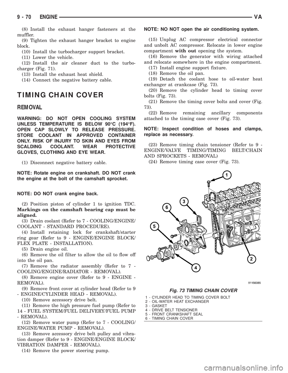
(1) Disconnect negative battery cable.
NOTE: Rotate engine on crankshaft. DO NOT crank
the engine at the bolt of the camshaft sprocket.
NOTE: DO NOT crank engine back.
(2) Position piston of cylinder 1 to ignition TDC.
Markings on the camshaft bearing cap must be
aligned.
(3) Drain coolant (Refer to 7 - COOLING/ENGINE/
COOLANT - STANDARD PROCEDURE).
(4) Install retaining lock for crankshaft/starter
ring gear (Refer to 9 - ENGINE/ENGINE BLOCK/
FLEX PLATE - INSTALLATION).
(5) Drain engine oil.
(6) Remove the oil filter to allow the oil to flow off
into the oil pan.
(7) Remove the radiator assembly (Refer to 7 -
COOLING/ENGINE/RADIATOR - REMOVAL).
(8) Remove engine cover (Refer to 9 - ENGINE -
REMOVAL).
(9) Remove front cover at cylinder head (Refer to 9
- ENGINE/CYLINDER HEAD - REMOVAL).
(10) Remove accessory drive belt.
(11) Remove the high pressure fuel pump (Refer to
14 - FUEL SYSTEM/FUEL DELIVERY/FUEL PUMP
- REMOVAL).
(12) Remove water pump (Refer to 7 - COOLING/
ENGINE/WATER PUMP - REMOVAL).
(13) Remove accessory drive belt pulley and vibra-
tion damper (Refer to 9 - ENGINE/ENGINE BLOCK/
VIBRATION DAMPER - REMOVAL).
(14) Remove the power steering pump.NOTE: NO NOT open the air conditioning system.
(15) Unplug AC compressor electrical connector
and unbolt AC compressor. Relocate in lower engine
compartmentwith outopening the system.
(16) Remove the generator with wiring attached
and relocate somewhere in the engine compartment.
(17) Install engine support fixture.
(18) Remove the oil pan.
(19) Detach the coolant hose to oil-water heat
exchanger at crankcase (Fig. 73).
(20) Remove the cylinder head to timing cover
bolts (Fig. 73).
(21) Remove the timing cover bolts and cover (Fig.
73).
(22) Remove remaining ancillary components
attached to the timing case cover (Fig. 73).
NOTE: Inspect condition of hoses and clamps,
replace as necessary.
(23) Remove timing chain tensioner (Refer to 9 -
ENGINE/VALVE TIMING/TIMING BELT/CHAIN
AND SPROCKETS - REMOVAL)
(24) Remove timing case cover (Fig. 73).
Fig. 73 TIMING CHAIN COVER
1 - CYLINDER HEAD TO TIMING COVER BOLT
2 - OIL-WATER HEAT EXCHANGER
3 - GASKET
4 - DRIVE BELT TENSIONER
5 - FRONT CRANKSHAFT SEAL
6 - TIMING CHAIN COVER
9 - 70 ENGINEVA
Page 1646 of 2305
INSTALLATION
CAUTION: Care must be taken to closley inspect
the gasket area around the time case cover to cyl-
inder head gasket coolant port. If damage is found,
replace the cylinder head gasket. Failure to do so
may result in engine damage.
NOTE: Thoroughly clean all mating surfaces with
the appropriate solvents to assure that no grease or
oil is present during assembly.
(1) Inspect cylinder head gasket and oil pan gas-
ket. If damaged, replace.
(2) Replace the front crankshaft seal (Refer to 9 -
ENGINE/ENGINE BLOCK/CRANKSHAFT OIL
SEAL - FRONT - INSTALLATION).
(3) Install ancillary components to timing case
cover.
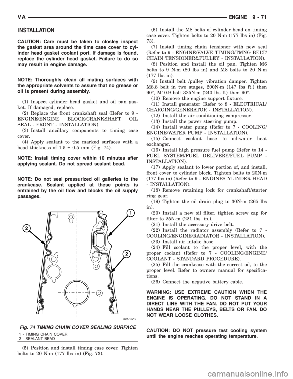
(4) Apply sealant to the marked surfaces with a
bead thickness of 1.5 0.5 mm (Fig. 74).
NOTE: Install timing cover within 10 minutes after
applying sealant. Do not spread sealant bead.
NOTE: Do not seal pressurized oil galleries to the
crankcase. Sealant applied at these points is
entrained by the oil flow and blocks the oil supply
passages.
(5) Position and install timing case cover. Tighten
bolts to 20 N´m (177 lbs in) (Fig. 73).(6) Install the M8 bolts of cylinder head on timing
case cover. Tighten bolts to 20 N´m (177 lbs in) (Fig.
73).
(7) Install timing chain tensioner with new seal
(Refer to 9 - ENGINE/VALVE TIMING/TMNG BELT/
CHAIN TENSIONER&PULLEY - INSTALLATION).
(8) Position and install the oil pan. Tighten M6
bolts to 9 N´m (80 lbs in) and M8 bolts to 20 N´m
(177 lbs in).
(9) Install belt /pulley vibration damper. Tighten
M8.8 bolt in two stages, 200N´m (147 lbs ft.) then
90É, M10.9 bolt 325N´m (240 lbs ft) then 90É.
(10) Remove the engine support fixture.
(11) Install generator (Refer to 8 - ELECTRICAL/
CHARGING/GENERATOR - INSTALLATION).
(12) Install the air conditioning compressor.
(13) Install the power steering pump.
(14) Install water pump (Refer to 7 - COOLING/
ENGINE/WATER PUMP - INSTALLATION).
(15) Connect coolant hose to oil-water heat
exchanger.
(16) Install high pressure fuel pump (Refer to 14 -
FUEL SYSTEM/FUEL DELIVERY/FUEL PUMP -
INSTALLATION).
(17) Apply sealant to lower portion of, and install,
front cover to cylinder block. Tighten bolts to 20N´m
(177 lbs in) (Refer to 9 - ENGINE/CYLINDER HEAD
- INSTALLATION).
(18) Remove retaining lock for crankshaft/starter
ring gear.
(19) Tighten the oil drain plug to 30N´m (265 lbs
in).
(20) Install a new oil filter. tighten screw cap for
filter to 25N´m (221 lbs. in.).
(21) Install the accessory drive belt.
(22) Install the radiator assembly (Refer to 7 -
COOLING/ENGINE/RADIATOR - INSTALLATION).
(23) Install air intake hose.
(24) Fill coolant to the proper level, with the
proper coolant (Refer to 7 - COOLING/ENGINE/
COOLANT - STANDARD PROCEDURE).
(25) Fill the crankcase with the correct oil, to the
proper level. Refer to owners manual for specifica-
tions.
(26) Connect the negative battery cable.
WARNING: USE EXTREME CAUTION WHEN THE
ENGINE IS OPERATING. DO NOT STAND IN A
DIRECT LINE WITH THE FAN. DO NOT PUT YOUR
HANDS NEAR THE PULLEYS, BELTS OR FAN. DO
NOT WEAR LOOSE CLOTHES.
CAUTION: DO NOT pressure test cooling system
until the engine reaches operating temperature.
Fig. 74 TIMING CHAIN COVER SEALING SURFACE
1 - TIMING CHAIN COVER
2 - SEALANT BEAD
VAENGINE 9 - 71
Page 1682 of 2305
FUEL SYSTEM
TABLE OF CONTENTS
page page
FUEL SYSTEM
WARNING
WARNING - HIGH FUEL SYSTEM
PRESSURE...........................1
WARNING............................1
DIAGNOSIS AND TESTING
DIAGNOSIS AND TESTING - HIGH
PRESSURE FUEL LINES.................1
DIAGNOSIS AND TESTING - AIR IN FUEL
SYSTEM.............................2
DIAGNOSIS AND TESTING - INJECTOR
LEAK QUANTITY.......................2STANDARD PROCEDURE
STANDARD PROCEDURES - CLEANING
FUEL SYSTEM COMPONENTS............3
STANDARD PROCEDURES - DRAINING
WATER FROM FUEL FILTER..............3
STANDARD PROCEDURE - LOW
PRESSURE FUEL PUMP TEST............4
FUEL DELIVERY..........................6
FUEL INJECTION........................31
FUEL SYSTEM
WARNING
WARNING - HIGH FUEL SYSTEM PRESSURE
WARNING: HIGH-PRESSURE FUEL LINES DELIVER
FUEL UNDER EXTREME PRESSURE FROM THE
INJECTION PUMP TO THE INJECTORS. THIS
MAYBE AS HIGH AS 1600BAR (23,200PSI). USE
EXTREME CAUTION WHEN INSPECTING FOR HIGH-
PRESSURE FUEL LEAKS. FUEL UNDER THIS
AMOUNT OF PRESSURE CAN PENETRATE SKIN
CAUSING PERSONAL INJURY OR DEATH. INSPECT
FOR HIGH-PRESSURE FUEL LEAKS WITH A SHEET
OF CARDBOARD PLACED IN THE SUSPECTED
AREA WHILE THE ENGINE IS NOT RUNNING.
START THE VEHICLE AND ALLOW THE ENGINE TO
RUN FOR A SHORT PERIOD. TURN THE ENGINE
OFF AND INSPECT THE PIECE OF CARDBOARD.
WEAR SAFETY GOGGLES AND ADEQUATE PRO-
TECTIVE CLOTHING WHEN SERVICING FUEL SYS-
TEM.
WARNING
WARNING: UNDER NO CIRCUMSTANCES SHOULD
GASOLINE BE MIXED WITH DIESEL FUEL (NOT
EVEN DURING WINTER). THE HIGH PRESSURE
PUMP IS LUBRICATED BY DIESEL FUEL. IMMEDI-
ATE FUEL SYSTEM DAMAGE MAY OCCUR CAUS-
ING REPLACEMENT AND FLUSHING OF THE
COMPLETE DIESEL FUEL SYSTEM. HIGH PRES-
SURE PUMP SEIZURE WILL CAUSE METAL PARTI-
CLES TO SPREAD THROUGH OUT THE FUELCIRCUIT. ALL CDI FUEL SYSTEM COMPONENTS
CONNECTED TO THE FUEL CIRCUIT WILL HAVE TO
BE EXCHANGED AND THE LINES FLUSHED.
DIAGNOSIS AND TESTING
DIAGNOSIS AND TESTING - HIGH PRESSURE
FUEL LINES
WARNING: HIGH-PRESSURE FUEL LINES DELIVER
FUEL UNDER EXTREME PRESSURE FROM THE
INJECTION PUMP TO THE INJECTORS. THIS
MAYBE AS HIGH AS 1600BAR (23,200PSI). USE
EXTREME CAUTION WHEN INSPECTING FOR HIGH-
PRESSURE FUEL LEAKS. FUEL UNDER THIS
AMOUNT OF PRESSURE CAN PENETRATE SKIN
CAUSING PERSONAL INJURY OR DEATH. INSPECT
FOR HIGH-PRESSURE FUEL LEAKS WITH A SHEET
OF CARDBOARD PLACED IN THE SUSPECTED
AREA WHILE THE ENGINE IS NOT RUNNING.
START THE VEHICLE AND ALLOW THE ENGINE TO
RUN FOR A SHORT PERIOD. TURN THE ENGINE
OFF AND INSPECT THE PIECE OF CARDBOARD.
WEAR SAFETY GOGGLES AND ADEQUATE PRO-
TECTIVE CLOTHING WHEN SERVICING FUEL SYS-
TEM.
High-pressure fuel line leaks can cause starting
problems and poor engine performance.
²Turn the engine off.
²Place a piece for cardboard in the suspected area
(Fig. 1).
²Start the engine and allow to run for a short
period.
²Turn the engine off.
²Inspect the cardboard.
VAFUEL SYSTEM 14 - 1
Page 1683 of 2305
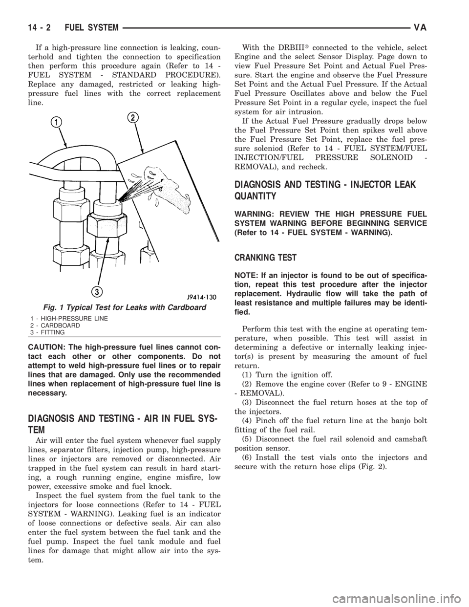
If a high-pressure line connection is leaking, coun-
terhold and tighten the connection to specification
then perform this procedure again (Refer to 14 -
FUEL SYSTEM - STANDARD PROCEDURE).
Replace any damaged, restricted or leaking high-
pressure fuel lines with the correct replacement
line.
CAUTION: The high-pressure fuel lines cannot con-
tact each other or other components. Do not
attempt to weld high-pressure fuel lines or to repair
lines that are damaged. Only use the recommended
lines when replacement of high-pressure fuel line is
necessary.
DIAGNOSIS AND TESTING - AIR IN FUEL SYS-
TEM
Air will enter the fuel system whenever fuel supply
lines, separator filters, injection pump, high-pressure
lines or injectors are removed or disconnected. Air
trapped in the fuel system can result in hard start-
ing, a rough running engine, engine misfire, low
power, excessive smoke and fuel knock.
Inspect the fuel system from the fuel tank to the
injectors for loose connections (Refer to 14 - FUEL
SYSTEM - WARNING). Leaking fuel is an indicator
of loose connections or defective seals. Air can also
enter the fuel system between the fuel tank and the
fuel pump. Inspect the fuel tank module and fuel
lines for damage that might allow air into the sys-
tem.With the DRBIIItconnected to the vehicle, select
Engine and the select Sensor Display. Page down to
view Fuel Pressure Set Point and Actual Fuel Pres-
sure. Start the engine and observe the Fuel Pressure
Set Point and the Actual Fuel Pressure. If the Actual
Fuel Pressure Oscillates above and below the Fuel
Pressure Set Point in a regular cycle, inspect the fuel
system for air intrusion.
If the Actual Fuel Pressure gradually drops below
the Fuel Pressure Set Point then spikes well above
the Fuel Pressure Set Point, replace the fuel pres-
sure soleniod (Refer to 14 - FUEL SYSTEM/FUEL
INJECTION/FUEL PRESSURE SOLENOID -
REMOVAL), and recheck.
DIAGNOSIS AND TESTING - INJECTOR LEAK
QUANTITY
WARNING: REVIEW THE HIGH PRESSURE FUEL
SYSTEM WARNING BEFORE BEGINNING SERVICE
(Refer to 14 - FUEL SYSTEM - WARNING).
CRANKING TEST
NOTE: If an injector is found to be out of specifica-
tion, repeat this test procedure after the injector
replacement. Hydraulic flow will take the path of
least resistance and multiple failures may be identi-
fied.
Perform this test with the engine at operating tem-
perature, when possible. This test will assist in
determining a defective or internally leaking injec-
tor(s) is present by measuring the amount of fuel
return.
(1) Turn the ignition off.
(2) Remove the engine cover (Refer to 9 - ENGINE
- REMOVAL).
(3) Disconnect the fuel return hoses at the top of
the injectors.
(4) Pinch off the fuel return line at the banjo bolt
fitting of the fuel rail.
(5) Disconnect the fuel rail solenoid and camshaft
position sensor.
(6) Install the test vials onto the injectors and
secure with the return hose clips (Fig. 2).
Fig. 1 Typical Test for Leaks with Cardboard
1 - HIGH-PRESSURE LINE
2 - CARDBOARD
3 - FITTING
14 - 2 FUEL SYSTEMVA