Page 1893 of 2305
ASSEMBLY
(1) Check all sealing rings (2-4, 6) (Fig. 177),
replace if necessary. The rounded off edges on the
sealing rings (2, 4, 6) must point outwards.
Fig. 177 Holding Clutch B2/B3 Seals
1 - PISTON GUIDE RING 4 - B2 PISTON SEALING RING
2 - PISTON GUIDE RING SEALING RING 5 - B3 PISTON/B2 OUTER DISC CARRIER
3 - PISTON GUIDE RING SEALING RING 6 - B3 PISTON SEALING RING
21 - 150 AUTOMATIC TRANSMISSION NAG1 - SERVICE INFORMATIONVA
Page 1894 of 2305
(2) Assemble piston guide (4) (Fig. 178) and B3
piston (8) in the correct position. Verify that the
missing tooth in the B3 piston/B2 outer disc carrier
(8) is aligned with the centerline of the two threaded
holes in the B2 and B3 piston guide (4).
(3) Insert B2 piston (10) (Fig. 178) in B3 piston
(8).
Fig. 178 Holding Clutch B2
1 - SNAP-RING 9 - B2 PISTON SEALING RING
2 - MULTIPLE DISC PACK 10 - B2 PISTON
3 - DISC SPRING 11 - PISTON GUIDE SEALING RING
4 - B2 AND B3 PISTON GUIDE 12 - PISTON GUIDE SEALING RING
5 - O-RING 13 - PISTON GUIDE RING
6 - B3 PISTON SEALING RING 14 - PISTON BACK PRESSURE DISC SPRING
7 - B3 PISTON SEALING RING 15 - SPRING PLATE
8 - B3 PISTON/B2 OUTER DISC CARRIER 16 - SNAP-RING
VAAUTOMATIC TRANSMISSION NAG1 - SERVICE INFORMATION 21 - 151
Page 1895 of 2305
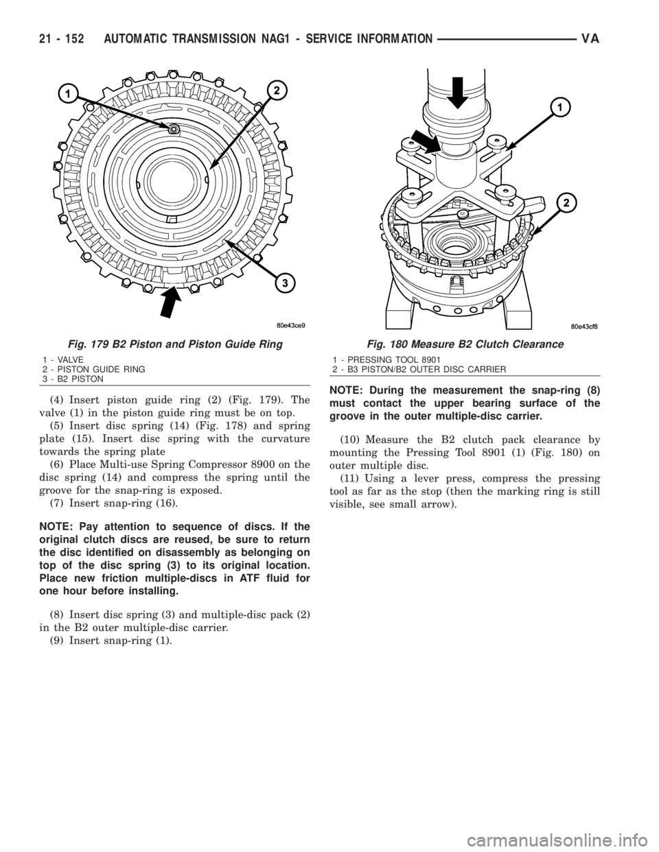
(4) Insert piston guide ring (2) (Fig. 179). The
valve (1) in the piston guide ring must be on top.
(5) Insert disc spring (14) (Fig. 178) and spring
plate (15). Insert disc spring with the curvature
towards the spring plate
(6) Place Multi-use Spring Compressor 8900 on the
disc spring (14) and compress the spring until the
groove for the snap-ring is exposed.
(7) Insert snap-ring (16).
NOTE: Pay attention to sequence of discs. If the
original clutch discs are reused, be sure to return
the disc identified on disassembly as belonging on
top of the disc spring (3) to its original location.
Place new friction multiple-discs in ATF fluid for
one hour before installing.
(8) Insert disc spring (3) and multiple-disc pack (2)
in the B2 outer multiple-disc carrier.
(9) Insert snap-ring (1).NOTE: During the measurement the snap-ring (8)
must contact the upper bearing surface of the
groove in the outer multiple-disc carrier.
(10) Measure the B2 clutch pack clearance by
mounting the Pressing Tool 8901 (1) (Fig. 180) on
outer multiple disc.
(11) Using a lever press, compress the pressing
tool as far as the stop (then the marking ring is still
visible, see small arrow).
Fig. 179 B2 Piston and Piston Guide Ring
1 - VALVE
2 - PISTON GUIDE RING
3 - B2 PISTON
Fig. 180 Measure B2 Clutch Clearance
1 - PRESSING TOOL 8901
2 - B3 PISTON/B2 OUTER DISC CARRIER
21 - 152 AUTOMATIC TRANSMISSION NAG1 - SERVICE INFORMATIONVA
Page 1896 of 2305
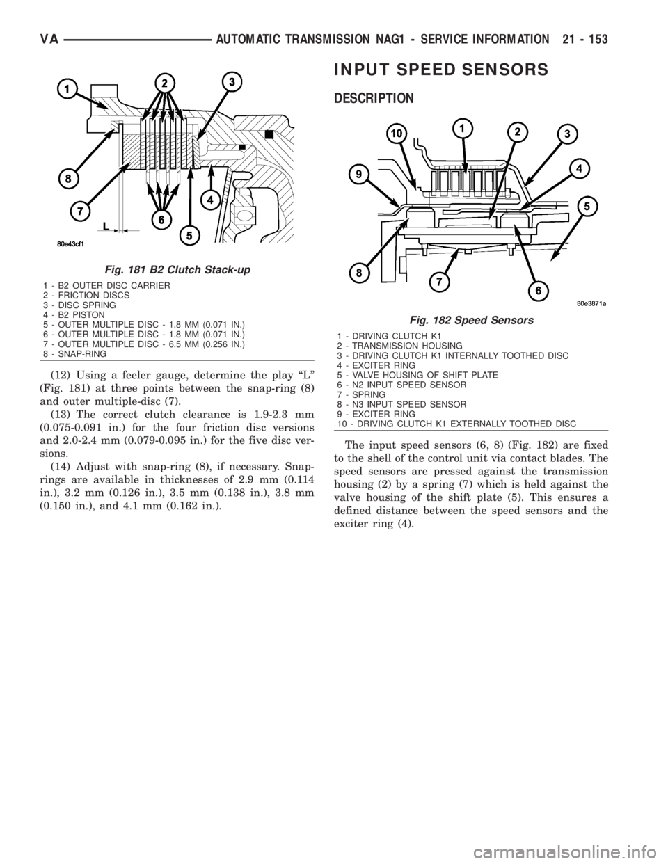
(12) Using a feeler gauge, determine the play ªLº
(Fig. 181) at three points between the snap-ring (8)
and outer multiple-disc (7).
(13) The correct clutch clearance is 1.9-2.3 mm
(0.075-0.091 in.) for the four friction disc versions
and 2.0-2.4 mm (0.079-0.095 in.) for the five disc ver-
sions.
(14) Adjust with snap-ring (8), if necessary. Snap-
rings are available in thicknesses of 2.9 mm (0.114
in.), 3.2 mm (0.126 in.), 3.5 mm (0.138 in.), 3.8 mm
(0.150 in.), and 4.1 mm (0.162 in.).
INPUT SPEED SENSORS
DESCRIPTION
The input speed sensors (6, 8) (Fig. 182) are fixed
to the shell of the control unit via contact blades. The
speed sensors are pressed against the transmission
housing (2) by a spring (7) which is held against the
valve housing of the shift plate (5). This ensures a
defined distance between the speed sensors and the
exciter ring (4).
Fig. 181 B2 Clutch Stack-up
1 - B2 OUTER DISC CARRIER
2 - FRICTION DISCS
3 - DISC SPRING
4 - B2 PISTON
5 - OUTER MULTIPLE DISC - 1.8 MM (0.071 IN.)
6 - OUTER MULTIPLE DISC - 1.8 MM (0.071 IN.)
7 - OUTER MULTIPLE DISC - 6.5 MM (0.256 IN.)
8 - SNAP-RING
Fig. 182 Speed Sensors
1 - DRIVING CLUTCH K1
2 - TRANSMISSION HOUSING
3 - DRIVING CLUTCH K1 INTERNALLY TOOTHED DISC
4 - EXCITER RING
5 - VALVE HOUSING OF SHIFT PLATE
6 - N2 INPUT SPEED SENSOR
7 - SPRING
8 - N3 INPUT SPEED SENSOR
9 - EXCITER RING
10 - DRIVING CLUTCH K1 EXTERNALLY TOOTHED DISC
VAAUTOMATIC TRANSMISSION NAG1 - SERVICE INFORMATION 21 - 153
Page 1897 of 2305
OPERATION
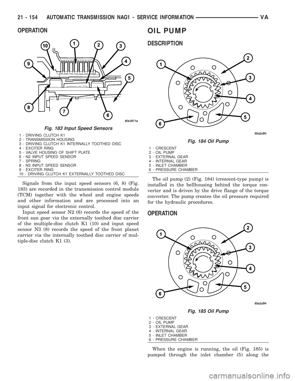
Signals from the input speed sensors (6, 8) (Fig.
183) are recorded in the transmission control module
(TCM) together with the wheel and engine speeds
and other information and are processed into an
input signal for electronic control.
Input speed sensor N2 (6) records the speed of the
front sun gear via the externally toothed disc carrier
of the multiple-disc clutch K1 (10) and input speed
sensor N3 (8) records the speed of the front planet
carrier via the internally toothed disc carrier of mul-
tiple-disc clutch K1 (3).
OIL PUMP
DESCRIPTION
The oil pump (2) (Fig. 184) (crescent-type pump) is
installed in the bellhousing behind the torque con-
verter and is driven by the drive flange of the torque
converter. The pump creates the oil pressure required
for the hydraulic procedures.
OPERATION
When the engine is running, the oil (Fig. 185) is
pumped through the inlet chamber (5) along the
Fig. 183 Input Speed Sensors
1 - DRIVING CLUTCH K1
2 - TRANSMISSION HOUSING
3 - DRIVING CLUTCH K1 INTERNALLY TOOTHED DISC
4 - EXCITER RING
5 - VALVE HOUSING OF SHIFT PLATE
6 - N2 INPUT SPEED SENSOR
7 - SPRING
8 - N3 INPUT SPEED SENSOR
9 - EXCITER RING
10 - DRIVING CLUTCH K1 EXTERNALLY TOOTHED DISC
Fig. 184 Oil Pump
1 - CRESCENT
2 - OIL PUMP
3 - EXTERNAL GEAR
4 - INTERNAL GEAR
5 - INLET CHAMBER
6 - PRESSURE CHAMBER
Fig. 185 Oil Pump
1 - CRESCENT
2 - OIL PUMP
3 - EXTERNAL GEAR
4 - INTERNAL GEAR
5 - INLET CHAMBER
6 - PRESSURE CHAMBER
21 - 154 AUTOMATIC TRANSMISSION NAG1 - SERVICE INFORMATIONVA
Page 1898 of 2305
upper and lower side of the crescent (1) to the pres-
sure chamber (6) of the housing. The meshing of the
teeth prevents oil flowing from the delivery side to
the intake side. An external gear (3) is eccentrically
mounted in the pump housing. The external gear is
driven by the internal gear (4) which is connected to
the torque converter hub.
DISASSEMBLY
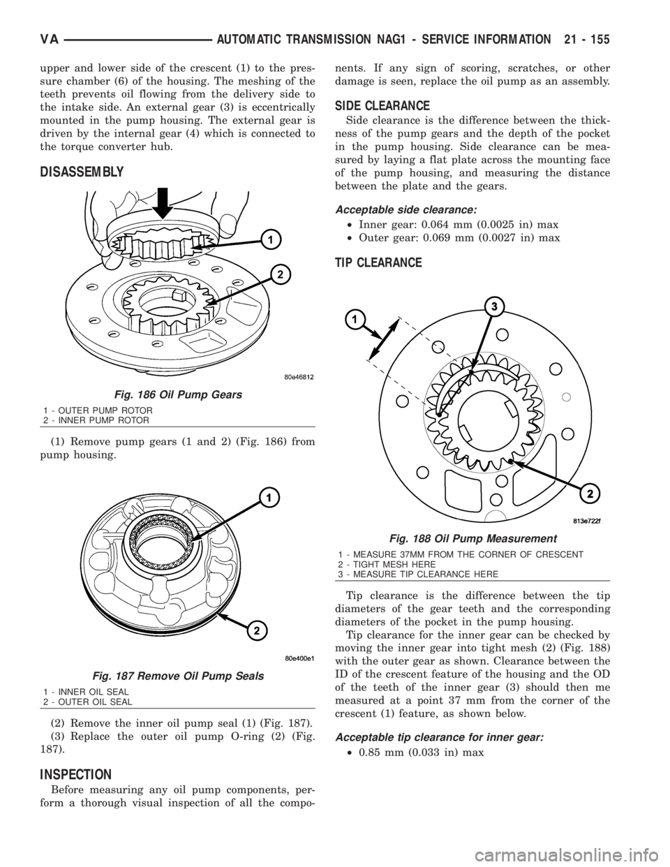
(1) Remove pump gears (1 and 2) (Fig. 186) from
pump housing.
(2) Remove the inner oil pump seal (1) (Fig. 187).
(3) Replace the outer oil pump O-ring (2) (Fig.
187).
INSPECTION
Before measuring any oil pump components, per-
form a thorough visual inspection of all the compo-nents. If any sign of scoring, scratches, or other
damage is seen, replace the oil pump as an assembly.
SIDE CLEARANCE
Side clearance is the difference between the thick-
ness of the pump gears and the depth of the pocket
in the pump housing. Side clearance can be mea-
sured by laying a flat plate across the mounting face
of the pump housing, and measuring the distance
between the plate and the gears.
Acceptable side clearance:
²Inner gear: 0.064 mm (0.0025 in) max
²Outer gear: 0.069 mm (0.0027 in) max
TIP CLEARANCE
Tip clearance is the difference between the tip
diameters of the gear teeth and the corresponding
diameters of the pocket in the pump housing.
Tip clearance for the inner gear can be checked by
moving the inner gear into tight mesh (2) (Fig. 188)
with the outer gear as shown. Clearance between the
ID of the crescent feature of the housing and the OD
of the teeth of the inner gear (3) should then me
measured at a point 37 mm from the corner of the
crescent (1) feature, as shown below.
Acceptable tip clearance for inner gear:
²0.85 mm (0.033 in) max
Fig. 186 Oil Pump Gears
1 - OUTER PUMP ROTOR
2 - INNER PUMP ROTOR
Fig. 187 Remove Oil Pump Seals
1 - INNER OIL SEAL
2 - OUTER OIL SEAL
Fig. 188 Oil Pump Measurement
1 - MEASURE 37MM FROM THE CORNER OF CRESCENT
2 - TIGHT MESH HERE
3 - MEASURE TIP CLEARANCE HERE
VAAUTOMATIC TRANSMISSION NAG1 - SERVICE INFORMATION 21 - 155
Page 1899 of 2305
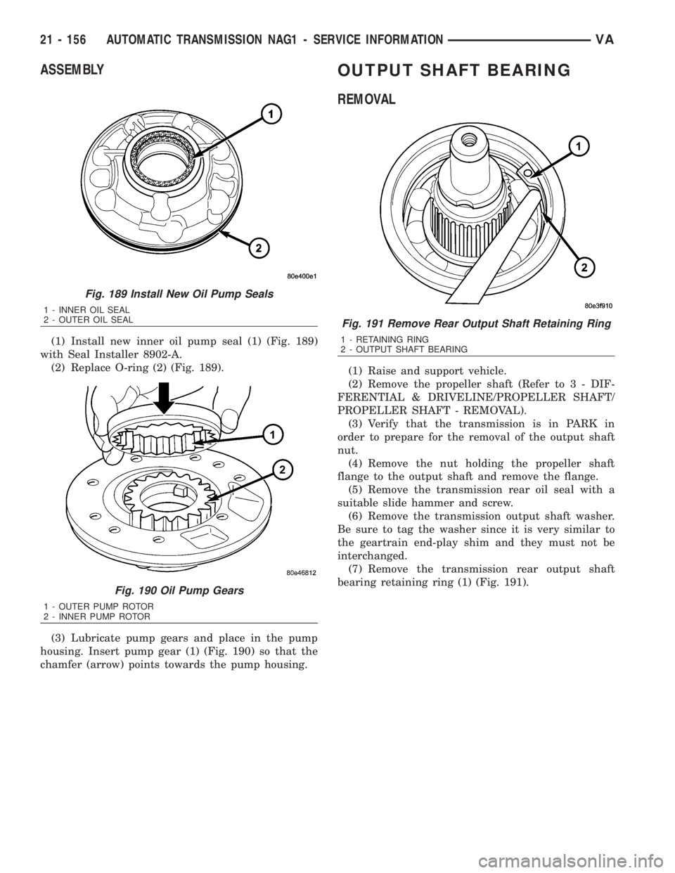
ASSEMBLY
(1) Install new inner oil pump seal (1) (Fig. 189)
with Seal Installer 8902-A.
(2) Replace O-ring (2) (Fig. 189).
(3) Lubricate pump gears and place in the pump
housing. Insert pump gear (1) (Fig. 190) so that the
chamfer (arrow) points towards the pump housing.
OUTPUT SHAFT BEARING
REMOVAL
(1) Raise and support vehicle.
(2) Remove the propeller shaft (Refer to 3 - DIF-
FERENTIAL & DRIVELINE/PROPELLER SHAFT/
PROPELLER SHAFT - REMOVAL).
(3) Verify that the transmission is in PARK in
order to prepare for the removal of the output shaft
nut.
(4) Remove the nut holding the propeller shaft
flange to the output shaft and remove the flange.
(5) Remove the transmission rear oil seal with a
suitable slide hammer and screw.
(6) Remove the transmission output shaft washer.
Be sure to tag the washer since it is very similar to
the geartrain end-play shim and they must not be
interchanged.
(7) Remove the transmission rear output shaft
bearing retaining ring (1) (Fig. 191).
Fig. 189 Install New Oil Pump Seals
1 - INNER OIL SEAL
2 - OUTER OIL SEAL
Fig. 190 Oil Pump Gears
1 - OUTER PUMP ROTOR
2 - INNER PUMP ROTOR
Fig. 191 Remove Rear Output Shaft Retaining Ring
1 - RETAINING RING
2 - OUTPUT SHAFT BEARING
21 - 156 AUTOMATIC TRANSMISSION NAG1 - SERVICE INFORMATIONVA
Page 1900 of 2305
(8) Position Bearing Remover 9082 (1) (Fig. 192)
over the inner race of the output shaft bearing.
(9) Slide the collar (3) (Fig. 193) on the Bearing
Remover 9082 (1) downward over the fingers (3) of
the tool.CAUTION: Verify that the geartrain end-play shim
has remained on the output shaft and against the
park gear. The shim may be adhered to the bearing
inner race. Retrieve the shim from the bearing and
install over the output shaft and against the park
gear.
(10) Remove the output shaft bearing (3) (Fig.
194).
Fig. 192 Position Remover 9082 On Bearing
1 - BEARING REMOVER 9082
2 - TRANSMISSION CASE
3 - OUTPUT SHAFT BEARING
Fig. 193 Slide Remover 9082 Collar Downward
1 - BEARING REMOVER 9082
2 - TRANSMISSION CASE
3 - COLLAR
4 - FINGERS
Fig. 194 Remove Output Shaft Bearing
1 - BEARING REMOVER 9082
2 - TRANSMISSION CASE
3 - OUTPUT SHAFT BEARING
VAAUTOMATIC TRANSMISSION NAG1 - SERVICE INFORMATION 21 - 157