Page 1917 of 2305
SHIFT PRESSURE CONTROL SOLENOID VALVE
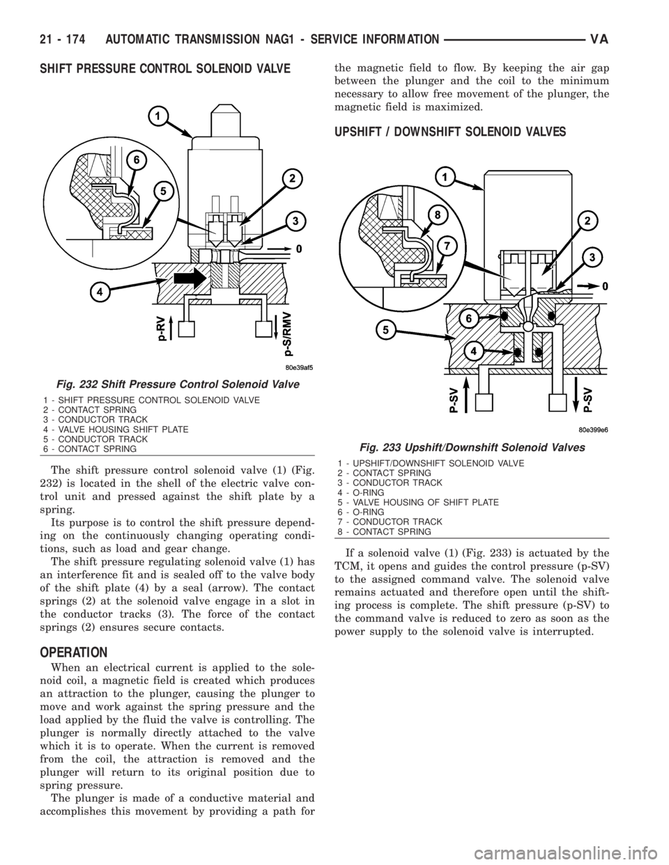
The shift pressure control solenoid valve (1) (Fig.
232) is located in the shell of the electric valve con-
trol unit and pressed against the shift plate by a
spring.
Its purpose is to control the shift pressure depend-
ing on the continuously changing operating condi-
tions, such as load and gear change.
The shift pressure regulating solenoid valve (1) has
an interference fit and is sealed off to the valve body
of the shift plate (4) by a seal (arrow). The contact
springs (2) at the solenoid valve engage in a slot in
the conductor tracks (3). The force of the contact
springs (2) ensures secure contacts.
OPERATION
When an electrical current is applied to the sole-
noid coil, a magnetic field is created which produces
an attraction to the plunger, causing the plunger to
move and work against the spring pressure and the
load applied by the fluid the valve is controlling. The
plunger is normally directly attached to the valve
which it is to operate. When the current is removed
from the coil, the attraction is removed and the
plunger will return to its original position due to
spring pressure.
The plunger is made of a conductive material and
accomplishes this movement by providing a path forthe magnetic field to flow. By keeping the air gap
between the plunger and the coil to the minimum
necessary to allow free movement of the plunger, the
magnetic field is maximized.
UPSHIFT / DOWNSHIFT SOLENOID VALVES
If a solenoid valve (1) (Fig. 233) is actuated by the
TCM, it opens and guides the control pressure (p-SV)
to the assigned command valve. The solenoid valve
remains actuated and therefore open until the shift-
ing process is complete. The shift pressure (p-SV) to
the command valve is reduced to zero as soon as the
power supply to the solenoid valve is interrupted.
Fig. 232 Shift Pressure Control Solenoid Valve
1 - SHIFT PRESSURE CONTROL SOLENOID VALVE
2 - CONTACT SPRING
3 - CONDUCTOR TRACK
4 - VALVE HOUSING SHIFT PLATE
5 - CONDUCTOR TRACK
6 - CONTACT SPRING
Fig. 233 Upshift/Downshift Solenoid Valves
1 - UPSHIFT/DOWNSHIFT SOLENOID VALVE
2 - CONTACT SPRING
3 - CONDUCTOR TRACK
4 - O-RING
5 - VALVE HOUSING OF SHIFT PLATE
6 - O-RING
7 - CONDUCTOR TRACK
8 - CONTACT SPRING
21 - 174 AUTOMATIC TRANSMISSION NAG1 - SERVICE INFORMATIONVA
Page 1918 of 2305
MODULATING PRESSURE CONTROL SOLENOID
VALVE
The modulating pressure regulating solenoid valve
(1) (Fig. 234) assigns a proportional pressure to the
current which is controlled by the TCM according to
the load.
TORQUE CONVERTER LOCKUP CLUTCH PWM
SOLENOID VALVE
The torque converter lockup PWM solenoid (1)
(Fig. 235) valve converts pulse-wave-modulated cur-
rent controlled by the TCM into the appropriate
hydraulic control pressure (p-S/TCC).
Fig. 234 Modulating Pressure Control Solenoid
Valve
1 - MODULATING PRESSURE CONTROL SOLENOID VALVE
2 - CONTACT SPRING
3 - CONDUCTOR TRACK
4 - VALVE HOUSING SHIFT PLATE
5 - CONDUCTOR TRACK
6 - CONTACT SPRING
Fig. 235 Torque Converter Lockup Clutch PWM
Solenoid Valve
1 - TORQUE CONVERTER LOCKUP CLUTCH PWM SOLENOID
VA LV E
2 - CONTACT SPRING
3 - CONDUCTOR TRACK
4 - VALVE HOUSING OF SHIFT PLATE
5 - O-RING
6 - CONDUCTOR TRACK
7 - CONTACT SPRING
VAAUTOMATIC TRANSMISSION NAG1 - SERVICE INFORMATION 21 - 175
Page 1919 of 2305
SHIFT PRESSURE CONTROL SOLENOID VALVE
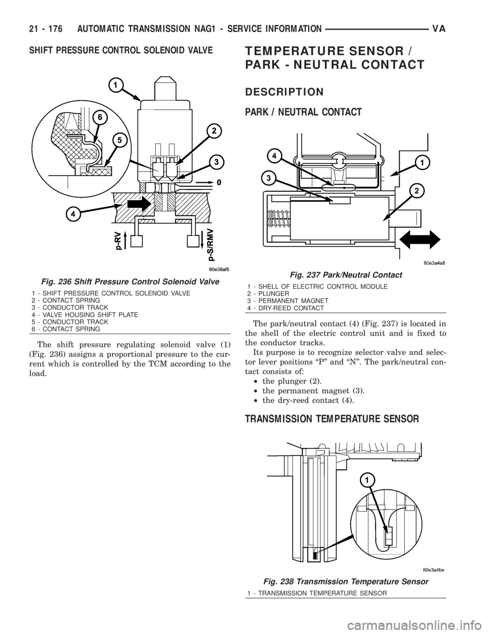
The shift pressure regulating solenoid valve (1)
(Fig. 236) assigns a proportional pressure to the cur-
rent which is controlled by the TCM according to the
load.
TEMPERATURE SENSOR /
PARK - NEUTRAL CONTACT
DESCRIPTION
PARK / NEUTRAL CONTACT
The park/neutral contact (4) (Fig. 237) is located in
the shell of the electric control unit and is fixed to
the conductor tracks.
Its purpose is to recognize selector valve and selec-
tor lever positions ªPº and ªNº. The park/neutral con-
tact consists of:
²the plunger (2).
²the permanent magnet (3).
²the dry-reed contact (4).
TRANSMISSION TEMPERATURE SENSOR
Fig. 236 Shift Pressure Control Solenoid Valve
1 - SHIFT PRESSURE CONTROL SOLENOID VALVE
2 - CONTACT SPRING
3 - CONDUCTOR TRACK
4 - VALVE HOUSING SHIFT PLATE
5 - CONDUCTOR TRACK
6 - CONTACT SPRING
Fig. 237 Park/Neutral Contact
1 - SHELL OF ELECTRIC CONTROL MODULE
2 - PLUNGER
3 - PERMANENT MAGNET
4 - DRY-REED CONTACT
Fig. 238 Transmission Temperature Sensor
1 - TRANSMISSION TEMPERATURE SENSOR
21 - 176 AUTOMATIC TRANSMISSION NAG1 - SERVICE INFORMATIONVA
Page 1920 of 2305
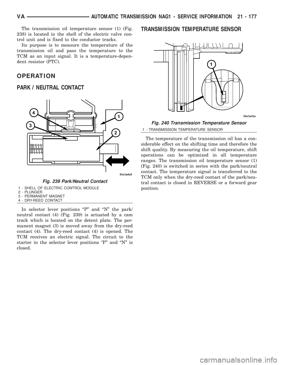
The transmission oil temperature sensor (1) (Fig.
238) is located in the shell of the electric valve con-
trol unit and is fixed to the conductor tracks.
Its purpose is to measure the temperature of the
transmission oil and pass the temperature to the
TCM as an input signal. It is a temperature-depen-
dent resistor (PTC).
OPERATION
PARK / NEUTRAL CONTACT
In selector lever positions ªPº and ªNº the park/
neutral contact (4) (Fig. 239) is actuated by a cam
track which is located on the detent plate. The per-
manent magnet (3) is moved away from the dry-reed
contact (4). The dry-reed contact (4) is opened. The
TCM receives an electric signal. The circuit to the
starter in the selector lever positions9Pº and ªNº is
closed.
TRANSMISSION TEMPERATURE SENSOR
The temperature of the transmission oil has a con-
siderable effect on the shifting time and therefore the
shift quality. By measuring the oil temperature, shift
operations can be optimized in all temperature
ranges. The transmission oil temperature sensor (1)
(Fig. 240) is switched in series with the park/neutral
contact. The temperature signal is transferred to the
TCM only when the dry-reed contact of the park/neu-
tral contact is closed in REVERSE or a forward gear
position.
Fig. 239 Park/Neutral Contact
1 - SHELL OF ELECTRIC CONTROL MODULE
2 - PLUNGER
3 - PERMANENT MAGNET
4 - DRY-REED CONTACT
Fig. 240 Transmission Temperature Sensor
1 - TRANSMISSION TEMPERATURE SENSOR
VAAUTOMATIC TRANSMISSION NAG1 - SERVICE INFORMATION 21 - 177
Page 1921 of 2305
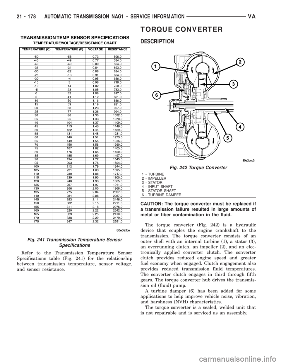
Refer to the Transmission Temperature Sensor
Specifications table (Fig. 241) for the relationship
between transmission temperature, sensor voltage,
and sensor resistance.
TORQUE CONVERTER
DESCRIPTION
CAUTION: The torque converter must be replaced if
a transmission failure resulted in large amounts of
metal or fiber contamination in the fluid.
The torque converter (Fig. 242) is a hydraulic
device that couples the engine crankshaft to the
transmission. The torque converter consists of an
outer shell with an internal turbine (1), a stator (3),
an overrunning clutch, an impeller (2), and an elec-
tronically applied converter clutch. The converter
clutch provides reduced engine speed and greater
fuel economy when engaged. Clutch engagement also
provides reduced transmission fluid temperatures.
The converter clutch engages in third through fifth
gears. The torque converter hub drives the transmis-
sion oil (fluid) pump.
A turbine damper (6) has been added for some
applications to help improve vehicle noise, vibration,
and harshness (NVH) characteristics.
The torque converter is a sealed, welded unit that
is not repairable and is serviced as an assembly.
Fig. 241 Transmission Temperature Sensor
Specifications
Fig. 242 Torque Converter
1 - TURBINE
2 - IMPELLER
3-STATOR
4 - INPUT SHAFT
5 - STATOR SHAFT
6 - TURBINE DAMPER
21 - 178 AUTOMATIC TRANSMISSION NAG1 - SERVICE INFORMATIONVA
Page 1922 of 2305
IMPELLER
The impeller (3) (Fig. 243) is an integral part of
the converter housing. The impeller consists of
curved blades placed radially along the inside of the
housing on the transmission side of the converter. As
the converter housing is rotated by the engine, so is
the impeller, because they are one and the same and
are the driving members of the system.
Fig. 243 Impeller
1 - ENGINE FLEXPLATE 4 - ENGINE ROTATION
2 - OIL FLOW FROM IMPELLER SECTION INTO TURBINE SEC-
TION5 - ENGINE ROTATION
3 - IMPELLER VANES AND COVER ARE INTEGRAL
VAAUTOMATIC TRANSMISSION NAG1 - SERVICE INFORMATION 21 - 179
Page 1923 of 2305
TURBINE
The turbine (1) (Fig. 244) is the output, or driven,
member of the converter. The turbine is mounted
within the housing opposite the impeller, but is not
attached to the housing. The input shaft is inserted
through the center of the impeller and splined into
the turbine. The design of the turbine is similar to
the impeller, except the blades of the turbine are
curved in the opposite direction.
Fig. 244 Turbine
1 - TURBINE VANE 4 - PORTION OF TORQUE CONVERTER COVER
2 - ENGINE ROTATION 5 - ENGINE ROTATION
3 - INPUT SHAFT 6 - OIL FLOW WITHIN TURBINE SECTION
21 - 180 AUTOMATIC TRANSMISSION NAG1 - SERVICE INFORMATIONVA
Page 1924 of 2305
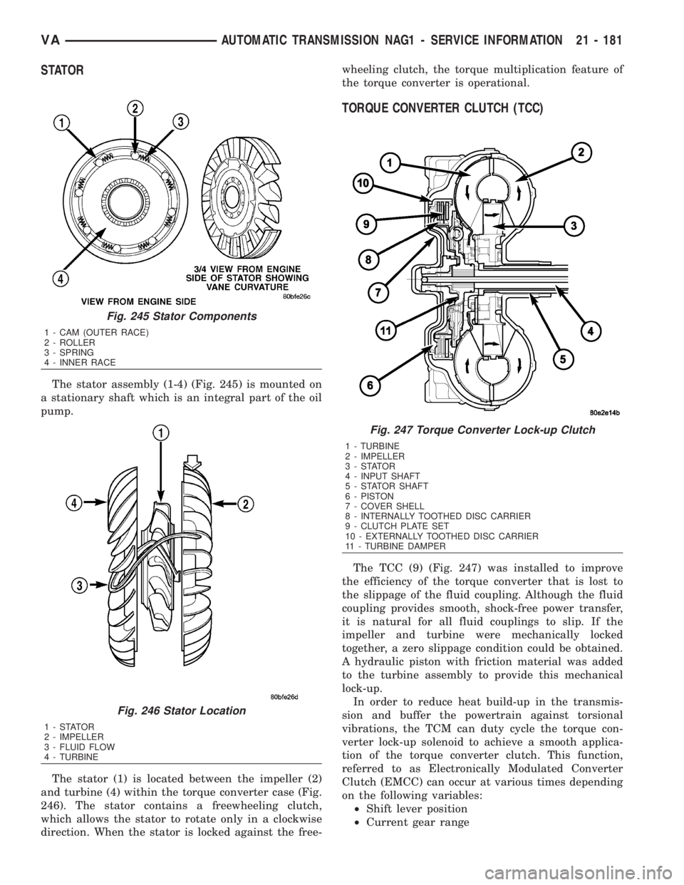
STATOR
The stator assembly (1-4) (Fig. 245) is mounted on
a stationary shaft which is an integral part of the oil
pump.
The stator (1) is located between the impeller (2)
and turbine (4) within the torque converter case (Fig.
246). The stator contains a freewheeling clutch,
which allows the stator to rotate only in a clockwise
direction. When the stator is locked against the free-wheeling clutch, the torque multiplication feature of
the torque converter is operational.
TORQUE CONVERTER CLUTCH (TCC)
The TCC (9) (Fig. 247) was installed to improve
the efficiency of the torque converter that is lost to
the slippage of the fluid coupling. Although the fluid
coupling provides smooth, shock-free power transfer,
it is natural for all fluid couplings to slip. If the
impeller and turbine were mechanically locked
together, a zero slippage condition could be obtained.
A hydraulic piston with friction material was added
to the turbine assembly to provide this mechanical
lock-up.
In order to reduce heat build-up in the transmis-
sion and buffer the powertrain against torsional
vibrations, the TCM can duty cycle the torque con-
verter lock-up solenoid to achieve a smooth applica-
tion of the torque converter clutch. This function,
referred to as Electronically Modulated Converter
Clutch (EMCC) can occur at various times depending
on the following variables:
²Shift lever position
²Current gear range
Fig. 245 Stator Components
1 - CAM (OUTER RACE)
2 - ROLLER
3 - SPRING
4 - INNER RACE
Fig. 246 Stator Location
1-STATOR
2 - IMPELLER
3 - FLUID FLOW
4 - TURBINE
Fig. 247 Torque Converter Lock-up Clutch
1 - TURBINE
2 - IMPELLER
3-STATOR
4 - INPUT SHAFT
5 - STATOR SHAFT
6 - PISTON
7 - COVER SHELL
8 - INTERNALLY TOOTHED DISC CARRIER
9 - CLUTCH PLATE SET
10 - EXTERNALLY TOOTHED DISC CARRIER
11 - TURBINE DAMPER
VAAUTOMATIC TRANSMISSION NAG1 - SERVICE INFORMATION 21 - 181