Page 1885 of 2305

OPERATION
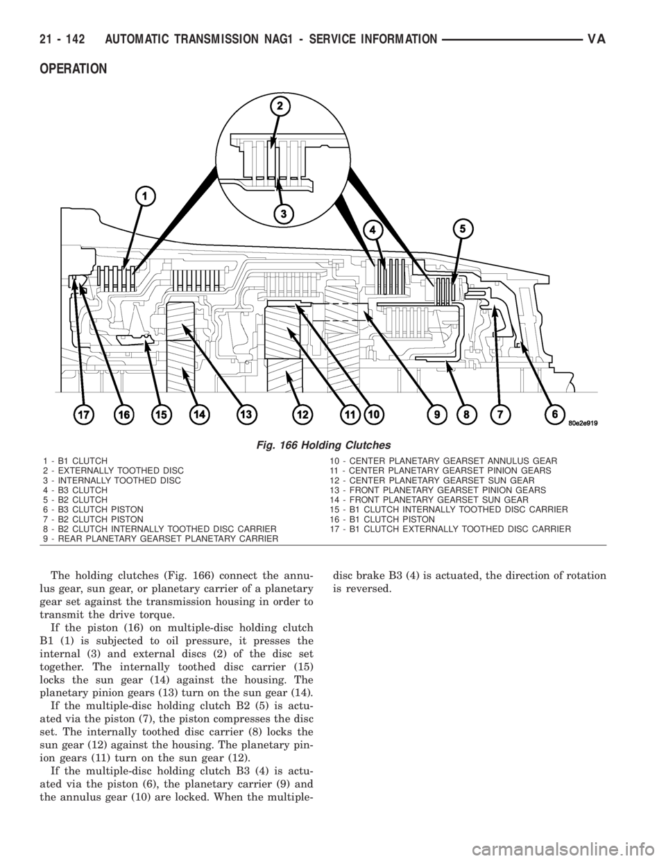
The holding clutches (Fig. 166) connect the annu-
lus gear, sun gear, or planetary carrier of a planetary
gear set against the transmission housing in order to
transmit the drive torque.
If the piston (16) on multiple-disc holding clutch
B1 (1) is subjected to oil pressure, it presses the
internal (3) and external discs (2) of the disc set
together. The internally toothed disc carrier (15)
locks the sun gear (14) against the housing. The
planetary pinion gears (13) turn on the sun gear (14).
If the multiple-disc holding clutch B2 (5) is actu-
ated via the piston (7), the piston compresses the disc
set. The internally toothed disc carrier (8) locks the
sun gear (12) against the housing. The planetary pin-
ion gears (11) turn on the sun gear (12).
If the multiple-disc holding clutch B3 (4) is actu-
ated via the piston (6), the planetary carrier (9) and
the annulus gear (10) are locked. When the multiple-disc brake B3 (4) is actuated, the direction of rotation
is reversed.
Fig. 166 Holding Clutches
1 - B1 CLUTCH 10 - CENTER PLANETARY GEARSET ANNULUS GEAR
2 - EXTERNALLY TOOTHED DISC 11 - CENTER PLANETARY GEARSET PINION GEARS
3 - INTERNALLY TOOTHED DISC 12 - CENTER PLANETARY GEARSET SUN GEAR
4 - B3 CLUTCH 13 - FRONT PLANETARY GEARSET PINION GEARS
5 - B2 CLUTCH 14 - FRONT PLANETARY GEARSET SUN GEAR
6 - B3 CLUTCH PISTON 15 - B1 CLUTCH INTERNALLY TOOTHED DISC CARRIER
7 - B2 CLUTCH PISTON 16 - B1 CLUTCH PISTON
8 - B2 CLUTCH INTERNALLY TOOTHED DISC CARRIER 17 - B1 CLUTCH EXTERNALLY TOOTHED DISC CARRIER
9 - REAR PLANETARY GEARSET PLANETARY CARRIER
21 - 142 AUTOMATIC TRANSMISSION NAG1 - SERVICE INFORMATIONVA
Page 1886 of 2305
HOLDING CLUTCH B1
DISASSEMBLY
(1) Remove the teflon rings (1) (Fig. 167) from the
B1 plate carrier hub (2).
Fig. 167 Remove the Teflon Rings
1 - TEFLON RINGS
2 - PLATE CARRIER HUB
VAAUTOMATIC TRANSMISSION NAG1 - SERVICE INFORMATION 21 - 143
Page 1887 of 2305
(2) Remove snap-ring (7) (Fig. 168).
(3) Remove multiple-disc pack (6) and disc spring
(5) from outer multiple-disc carrier. Note which
clutch disc is removed just prior to the disc spring (5)
for re-assembly. If the clutch discs are re-used, this
disc must be returned to its original position on top
of the disc spring.
(4) Place the Multi-use Spring Compressor 8900
(8) (Fig. 168) on disc spring (3) and compress the
spring until the snap-ring (4) is exposed.
(5) Remove snap-ring (4).
(6) Remove piston (2) from the outer multiple-disc
carrier by carefully blowing compressed air into the
bore (A).
Fig. 168 Holding Clutch B1
1 - HOLDING CLUTCH B1 OUTER CARRIER 5 - DISC SPRING
2 - PISTON 6 - MULTIPLE DISC PACK
3 - DISC SPRING 7 - SNAP-RING
4 - SNAP-RING 8 - MULTI-USE SPRING COMPRESSOR 8900
21 - 144 AUTOMATIC TRANSMISSION NAG1 - SERVICE INFORMATIONVA
Page 1888 of 2305
ASSEMBLY
NOTE: Check vulcanized gasket, replace if neces-
sary.
(1) Install piston (2) (Fig. 169) in outer multiple-
disc carrier (1).
(2) Place compressor (8) on disc spring (3) and
compress until the groove of the snap-ring is exposed.
NOTE: The collar of the snap-ring must point
towards the multiple-disc pack. After installing,
check snap-ring for correct seat.
(3) Insert snap-ring (4) (Fig. 169).
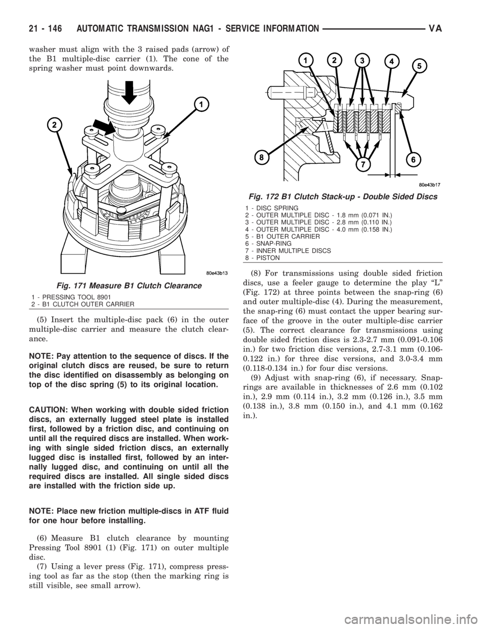
(4) Insert disc spring (2) (Fig. 170) in the outer
multiple-disc carrier. Observe the disc spring (2)
installation position. The lugs of the disc spring (2)
Fig. 169 Holding Clutch B1
1 - HOLDING CLUTCH B1 OUTER CARRIER 5 - DISC SPRING
2 - PISTON 6 - MULTIPLE DISC PACK
3 - DISC SPRING 7 - SNAP-RING
4 - SNAP-RING 8 - MULTI-USE SPRING COMPRESSOR 8900
Fig. 170 Install the Disc Spring
1 - B1 MULTIPLE-DISC CARRIER
2 - DISC SPRING
VAAUTOMATIC TRANSMISSION NAG1 - SERVICE INFORMATION 21 - 145
Page 1889 of 2305

washer must align with the 3 raised pads (arrow) of
the B1 multiple-disc carrier (1). The cone of the
spring washer must point downwards.
(5) Insert the multiple-disc pack (6) in the outer
multiple-disc carrier and measure the clutch clear-
ance.
NOTE: Pay attention to the sequence of discs. If the
original clutch discs are reused, be sure to return
the disc identified on disassembly as belonging on
top of the disc spring (5) to its original location.
CAUTION: When working with double sided friction
discs, an externally lugged steel plate is installed
first, followed by a friction disc, and continuing on
until all the required discs are installed. When work-
ing with single sided friction discs, an externally
lugged disc is installed first, followed by an inter-
nally lugged disc, and continuing on until all the
required discs are installed. All single sided discs
are installed with the friction side up.
NOTE: Place new friction multiple-discs in ATF fluid
for one hour before installing.
(6) Measure B1 clutch clearance by mounting
Pressing Tool 8901 (1) (Fig. 171) on outer multiple
disc.
(7) Using a lever press (Fig. 171), compress press-
ing tool as far as the stop (then the marking ring is
still visible, see small arrow).(8) For transmissions using double sided friction
discs, use a feeler gauge to determine the play ªLº
(Fig. 172) at three points between the snap-ring (6)
and outer multiple-disc (4). During the measurement,
the snap-ring (6) must contact the upper bearing sur-
face of the groove in the outer multiple-disc carrier
(5). The correct clearance for transmissions using
double sided friction discs is 2.3-2.7 mm (0.091-0.106
in.) for two friction disc versions, 2.7-3.1 mm (0.106-
0.122 in.) for three disc versions, and 3.0-3.4 mm
(0.118-0.134 in.) for four disc versions.
(9) Adjust with snap-ring (6), if necessary. Snap-
rings are available in thicknesses of 2.6 mm (0.102
in.), 2.9 mm (0.114 in.), 3.2 mm (0.126 in.), 3.5 mm
(0.138 in.), 3.8 mm (0.150 in.), and 4.1 mm (0.162
in.).
Fig. 171 Measure B1 Clutch Clearance
1 - PRESSING TOOL 8901
2 - B1 CLUTCH OUTER CARRIER
Fig. 172 B1 Clutch Stack-up - Double Sided Discs
1 - DISC SPRING
2 - OUTER MULTIPLE DISC - 1.8 mm (0.071 IN.)
3 - OUTER MULTIPLE DISC - 2.8 mm (0.110 IN.)
4 - OUTER MULTIPLE DISC - 4.0 mm (0.158 IN.)
5 - B1 OUTER CARRIER
6 - SNAP-RING
7 - INNER MULTIPLE DISCS
8 - PISTON
21 - 146 AUTOMATIC TRANSMISSION NAG1 - SERVICE INFORMATIONVA
Page 1890 of 2305

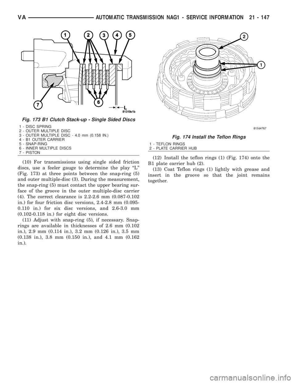
(10) For transmissions using single sided friction
discs, use a feeler gauge to determine the play ªLº
(Fig. 173) at three points between the snap-ring (5)
and outer multiple-disc (3). During the measurement,
the snap-ring (5) must contact the upper bearing sur-
face of the groove in the outer multiple-disc carrier
(4). The correct clearance is 2.2-2.6 mm (0.087-0.102
in.) for four friction disc versions, 2.4-2.8 mm (0.095-
0.110 in.) for six disc versions, and 2.6-3.0 mm
(0.102-0.118 in.) for eight disc versions.
(11) Adjust with snap-ring (5), if necessary. Snap-
rings are available in thicknesses of 2.6 mm (0.102
in.), 2.9 mm (0.114 in.), 3.2 mm (0.126 in.), 3.5 mm
(0.138 in.), 3.8 mm (0.150 in.), and 4.1 mm (0.162
in.).(12) Install the teflon rings (1) (Fig. 174) onto the
B1 plate carrier hub (2).
(13) Coat Teflon rings (1) lightly with grease and
insert in the groove so that the joint remains
together.
Fig. 173 B1 Clutch Stack-up - Single Sided Discs
1 - DISC SPRING
2 - OUTER MULTIPLE DISC
3 - OUTER MULTIPLE DISC - 4.0 mm (0.158 IN.)
4 - B1 OUTER CARRIER
5 - SNAP-RING
6 - INNER MULTIPLE DISCS
7 - PISTON
Fig. 174 Install the Teflon Rings
1 - TEFLON RINGS
2 - PLATE CARRIER HUB
VAAUTOMATIC TRANSMISSION NAG1 - SERVICE INFORMATION 21 - 147
Page 1891 of 2305

HOLDING CLUTCH B2
DISASSEMBLY
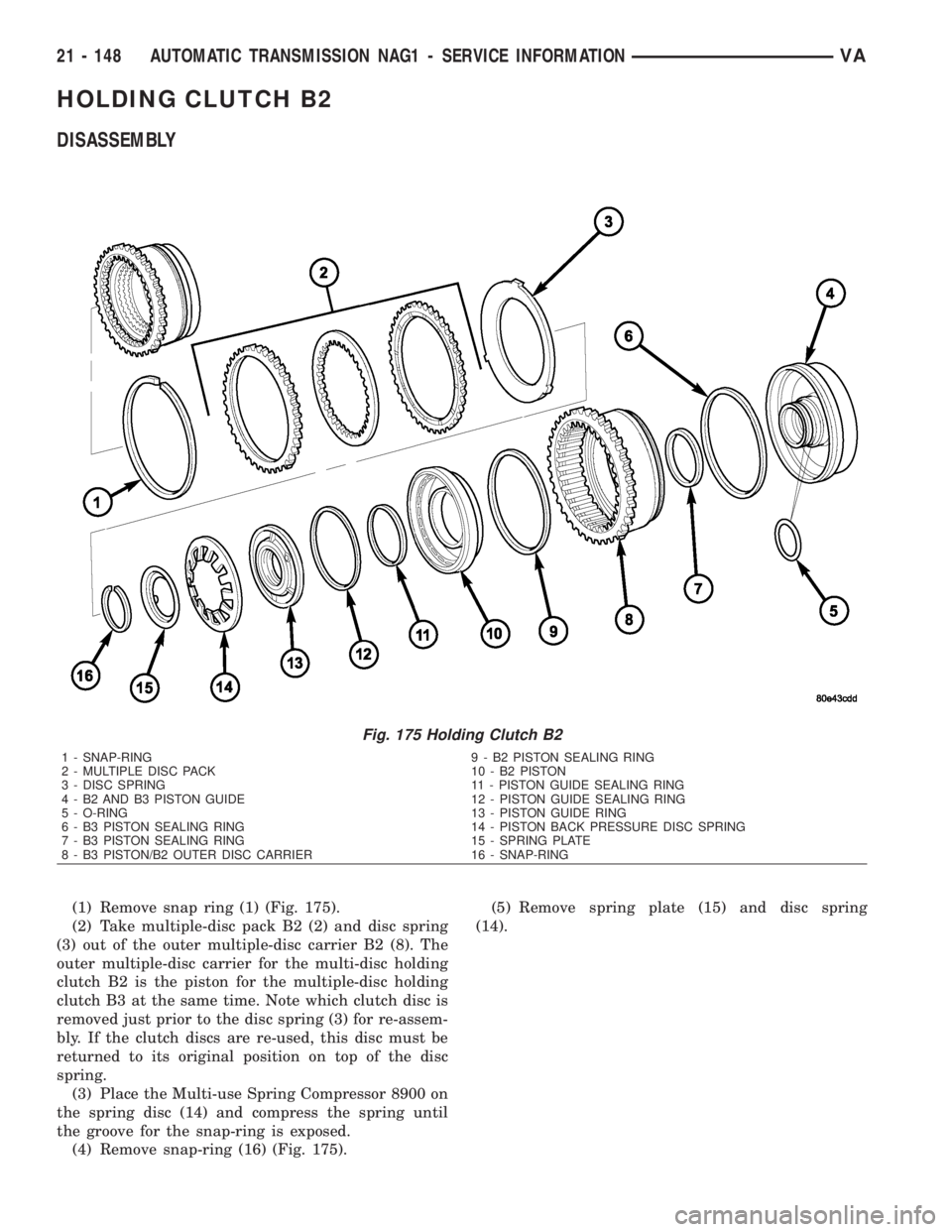
(1) Remove snap ring (1) (Fig. 175).
(2) Take multiple-disc pack B2 (2) and disc spring
(3) out of the outer multiple-disc carrier B2 (8). The
outer multiple-disc carrier for the multi-disc holding
clutch B2 is the piston for the multiple-disc holding
clutch B3 at the same time. Note which clutch disc is
removed just prior to the disc spring (3) for re-assem-
bly. If the clutch discs are re-used, this disc must be
returned to its original position on top of the disc
spring.
(3) Place the Multi-use Spring Compressor 8900 on
the spring disc (14) and compress the spring until
the groove for the snap-ring is exposed.
(4) Remove snap-ring (16) (Fig. 175).(5) Remove spring plate (15) and disc spring
(14).
Fig. 175 Holding Clutch B2
1 - SNAP-RING 9 - B2 PISTON SEALING RING
2 - MULTIPLE DISC PACK 10 - B2 PISTON
3 - DISC SPRING 11 - PISTON GUIDE SEALING RING
4 - B2 AND B3 PISTON GUIDE 12 - PISTON GUIDE SEALING RING
5 - O-RING 13 - PISTON GUIDE RING
6 - B3 PISTON SEALING RING 14 - PISTON BACK PRESSURE DISC SPRING
7 - B3 PISTON SEALING RING 15 - SPRING PLATE
8 - B3 PISTON/B2 OUTER DISC CARRIER 16 - SNAP-RING
21 - 148 AUTOMATIC TRANSMISSION NAG1 - SERVICE INFORMATIONVA
Page 1892 of 2305
(6) Separate piston guide ring (13) and the B2 pis-
ton (10) from the B3 piston (8) by blowing com-
pressed air into the bore (D) (Fig. 176).
(7) Press piston guide ring (13) out of the B2 pis-
ton (10).
(8) Separate piston guide (4) from the B3 piston
(8) by blowing compressed air into the bore (A) (Fig.
176).
Fig. 176 B2 Clutch Oil Supply Locations
A - B3 PISTON
B - B2 PISTON GUIDE RING SIDE
C - K3 CLUTCH FEED
D - B2 PISTON SHIFT SIDE
VAAUTOMATIC TRANSMISSION NAG1 - SERVICE INFORMATION 21 - 149