2006 MERCEDES-BENZ SPRINTER oil change
[x] Cancel search: oil changePage 793 of 2305
As the dragging brake overheats, efficiency is so
reduced that fade occurs. Since the opposite brake
unit is still functioning normally, its braking effect is
magnified. This causes pull to switch direction in
favor of the normally functioning brake unit.
An additional point when diagnosing a change in
pull condition concerns brake cool down. Remember
that pull will return to the original direction, if the
dragging brake unit is allowed to cool down (and is
not seriously damaged).
REAR BRAKE GRAB OR PULL
Rear grab or pull is usually caused by improperly
adjusted or seized parking brake cables, contami-
nated lining, bent or binding shoes and support
plates, or improperly assembled components. This is
particularly true when only one rear wheel is
involved. However, when both rear wheels are
affected, the master cylinder or proportioning valve
could be at fault.
BRAKES DO NOT HOLD AFTER DRIVING THROUGH DEEP
WATER PUDDLES
This condition is generally caused by water soaked
lining. If the lining is only wet, it can be dried by
driving with the brakes very lightly applied for a
mile or two. However, if the lining is both soaked and
dirt contaminated, cleaning and/or replacement will
be necessary.
BRAKE LINING CONTAMINATION
Brake lining contamination is mostly a product of
leaking calipers or worn seals, driving through deep
water puddles, or lining that has become covered
with grease and grit during repair. Contaminated lin-
ing should be replaced to avoid further brake prob-
lems.
WHEEL AND TIRE PROBLEMS
Some conditions attributed to brake components
may actually be caused by a wheel or tire problem.
A damaged wheel can cause shudder, vibration and
pull. A worn or damaged tire can also cause pull.
Severely worn tires with very little tread left can
produce a grab-like condition as the tire loses and
recovers traction. Flat-spotted tires can cause vibra-
tion and generate shudder during brake operation. A
tire with internal damage such as a severe bruise,
cut, or ply separation can cause pull and vibration.
BRAKE NOISES
Some brake noise is common with rear drum
brakes and on some disc brakes during the first few
stops after a vehicle has been parked overnight or
stored. This is primarily due to the formation of trace
corrosion (light rust) on metal surfaces. This light
corrosion is typically cleared from the metal surfacesafter a few brake applications causing the noise to
subside.
BRAKE SQUEAK / SQUEAL
Brake squeak or squeal may be due to linings that
are wet or contaminated with brake fluid, grease, or
oil. Glazed linings and rotors with hard spots can
also contribute to squeak. Dirt and foreign material
embedded in the brake lining will also cause squeak/
squeal.
A very loud squeak or squeal is frequently a sign of
severely worn brake lining. If the lining has worn
through to the brake pads in spots, metal-to-metal
contact occurs. If the condition is allowed to continue,
rotors can become so scored that replacement is nec-
essary.
BRAKE CHATTER
Brake chatter is usually caused by loose or worn
components, or glazed/burnt lining. Rotors with hard
spots can also contribute to chatter. Additional causes
of chatter are out-of-tolerance rotors, brake lining not
securely attached to the shoes, loose wheel bearings
and contaminated brake lining.
THUMP / CLUNK NOISE
Thumping or clunk noises during braking are fre-
quentlynotcaused by brake components. In many
cases, such noises are caused by loose or damaged
steering, suspension, or engine components. However,
calipers that bind on the slide surfaces can generate
a thump or clunk noise.
STANDARD PROCEDURE
STANDARD PROCEDURE - MANUAL BLEEDING
Use approved brake fluid (Refer to LUBRICATION
& MAINTENANCE/FLUID TYPES - DESCRIP-
TION). Use fresh, clean fluid from a sealed container
at all times.
(1) Remove reservoir filler caps and fill reservoir.
(2) If calipers, or wheel cylinders were overhauled,
open all caliper and wheel cylinder bleed screws.
Then close each bleed screw as fluid starts to drip
from it. Top off master cylinder reservoir once more
before proceeding.
(3) Attach one end of bleed hose to bleed screw
and insert opposite end in glass container partially
filled with brake fluid (Fig. 1). Be sure end of bleed
hose is immersed in fluid.
5 - 4 BRAKES - BASEVA
Page 859 of 2305

ECM Control Strategy The engine control module
is involved with a variety of functions such as: (Fig.
3)
²Individual injector activation
²Engine idle speed control to ensure smooth
engine idling independent of engine load
²Ride comfort function such as anti jerk control:
The CDI control module detects irregularities in
engine speed (resulting, for example, from load
changes or gear shift) from the signal supplied by the
crankshaft position sensor and reduces them by
adjusting the quantity injected into each of the cylin-
ders
²Constant RPM (high idle feature) for ambulance
vehicle bodies equipped with electrical appliances
²Starter control, immobilizer, cruise control, kick
down, air conditioner
²Maintenance computer ASSYST (optional)
²Glow plug for pre-heating, post heating and
intermittent heating
²Error code memory/diagnostics, communication
interface for diagnosis and handling the fault codes
²The maximum vehicle speed is programmable
from 19±82 m.p.h. The standard is 82 m.p.h.
Fig. 2 ECM
1 - MASS AIR FLOW SENSOR 8 - CHARGE AIR PRESSURE SENSOR
2 - TURBOCHARGER SERVO MOTOR 9 - CHARGE AIR TEMPERATURE SENSOR
3 - CAMSHAFT POSITION SENSOR 10 - COOLANT TEMPERATURE SENSOR
4 - ENGINE OIL SENSOR 11 - FUEL RAIL PRESSURE SENSOR
5 - CRANKSHAFT POSITION SENSOR 12 - FUEL TEMPERATURE SENSOR
6 - PRESSURE REGULATOR VALVE 13 - FUEL QUANTITY CONTROL VALVE
7 - EGR VALVE 14 - AIR INTAKE PRESSURE SENSOR
8E - 4 ELECTRONIC CONTROL MODULESVA
Page 918 of 2305

IGNITION CONTROL
TABLE OF CONTENTS
page page
IGNITION CONTROL
OPERATION - GLOW PLUG................1
SPECIAL TOOLS........................1
GLOW PLUG
REMOVAL.............................1
INSTALLATION..........................1GLOW PLUG RELAY
DESCRIPTION..........................1
OPERATION............................2
DIAGNOSIS AND TESTING - GLOW PLUG
RELAYS..............................2
IGNITION CONTROL
OPERATION - GLOW PLUG
Pre - Glowing
With the key in the On position, the glow plug out-
put stage and the indicator lamp are actuated by the
ECM. The pre-heating time is calculated by the ECM
in line with the coolant temperature. The glow plug
output stage switches the current through the glow
plugs. The glow plug indicator lamp goes out after a
pre-glow period has elapsed. Component or cable fail-
ures in the pre-glow system are indicated by the glow
plug lamp and stored in the ECM.
Glow Output Stage
With the ignition key in the On position a signal is
transmitted from the ECM to the glow plug output
stager. If no data is exchanged with the ECM the
glow plug stage is terminated after two seconds. The
glow plug out put stage constantly signals the cur-
rent operating state (ON/OFF) and any system
faults. The following faults are recognized by the out
put stage and transmitted to the ECM:
²Open circuit in one or more of the glow plug
leads
²Short circuit in the glow plug circuit
²Out put stage fault or temperature related shut-
off
If a failure in the glow plug system occurs, the
glow plug indicator lamp will be illuminated only as
long as the fault is current. If the failure is no longer
present, the glow plug indicator lamp will be
switched off but a code will be stored in the ECM.
After Glow
Once the engine has started, the ECM determines
the after glow time depending on cooling tempera-
ture. During this time the glow plugs continue to be
actuated by the glow plug output stage. This results
in improved smooth running after a cold start and
improved warming up properties, elimination of blueexhaust after a cold start up and a more stable cold
starting speed.
If no signal is received from the coolant tempera-
ture sensor the signal from the oil sensor is used as a
substitute.
SPECIAL TOOLS
GLOW PLUG
REMOVAL
(1) Disconnect the negative battery cable.
(2) Remove the engine cover.
(3) Use special tool #9286 pliers to unplug the
glow plug wiring harness connector(s) at the glow
plug.
(4) Remove the glow plug(s) (Fig. 1).
INSTALLATION
(1) Screw glow plug(s) into cylinder head and
tighten to 12 N´m (115 lbs. in) (Fig. 1).
(2) Connect the glow plug wiring harness connec-
tor(s)
(3) Install the engine cover.
(4) Connect negative battery cable.
GLOW PLUG RELAY
DESCRIPTION
The glow plug relay supplies battery voltage to the
glow plug through a timed cycle that is related to
coolant temperature. The glow plug relay is located
under the battery. The purpose of a glow plug system
GLOW PLUG PLIERS
VAIGNITION CONTROL 8I - 1
Page 924 of 2305

procedures, further details on wire harness routing
and retention, as well as pin-out and location views
for the various wire harness connectors, splices and
grounds.
The EMIC modules for this model are serviced only
as complete units. The EMIC module cannot be
adjusted or repaired. If a gauge, an LED indicator,
the multi-fuction indicator LCD unit, an electronic
tone generator, the electronic circuit board, the cir-
cuit board hardware, the cluster overlay, the cluster
housing, the cluster hood, the cluster lens, or the
cluster rear cover are damaged or faulty, the entire
EMIC module must be replaced.
OPERATION
The ElectroMechanical Instrument Cluster (EMIC)
is designed to allow the vehicle operator to monitor
the conditions of many of the vehicle components and
operating systems. The gauges, meters and indicators
in the EMIC provide valuable information about the
powertrain, fuel and emissions systems, cooling sys-
tem, lighting systems, safety systems and many
other convenience items. The EMIC is installed in
the instrument panel so that all of these monitors
can be easily viewed by the vehicle operator when
driving, while still allowing relative ease of access for
service. The microprocessor-based EMIC hardware
and software uses various inputs to control the
gauges and indicators visible on the face of the clus-
ter. Some of these inputs are hard wired, but many
are in the form of electronic messages that are trans-
mitted by other electronic modules over the Control-
ler Area Network (CAN) data bus network. (Refer to
8 - ELECTRICAL/ELECTRONIC CONTROL MOD-
ULES/COMMUNICATION - OPERATION).
The EMIC microprocessor smooths the input data
using algorithms to provide gauge readings that are
accurate, stable and responsive to operating condi-
tions. These algorithms are designed to provide
gauge readings during normal operation that are con-
sistent with customer expectations. However, when
abnormal conditions exist such as high coolant tem-
perature, the algorithm can drive the gauge pointer
to an extreme position and the microprocessor can
sound a chime through the on-board audible tone
generator to provide distinct visual and audible indi-
cations of a problem to the vehicle operator. The
instrument cluster circuitry also provides audible
turn signal and hazard warning support by emulat-
ing the ªtickingº sound associated with a conven-
tional electro-mechanical flasher using a contactless
relay. The relay will also provide an indication of a
turn signal failure by sounding at double the usual
frequency. Each audible warning is provided to the
vehicle operator to supplement a visual indication.
The EMIC circuitry operates on battery current
received through a non-switched fused B(+) circuit,
and on a fused ignition switch output circuit. TheEMIC circuitry is grounded through a ground circuit
and take out of the frame wire harness with an eye-
let terminal connector that is secured to a stud by a
nut at a ground location on the dash panel just for-
ward of the instrument cluster. Separate switched
ground inputs from the key-in ignition switch and
the front door jamb switches provide wake-up signals
to the EMIC circuitry. This arrangement allows the
EMIC to provide some features regardless of the igni-
tion switch position, while other features will operate
only with the ignition switch in the On position.
Proper diagnosis and testing of the EMIC, the
CAN data bus, the data bus electronic message
inputs to and outputs from the EMIC, as well as the
retrieval or erasure of a Diagnostic Trouble Code
(DTC) requires the use of a diagnostic scan tool.
Refer to the appropriate diagnostic information. See
the owner's manual in the vehicle glove box for more
information on the features, use and operation of the
EMIC.
GAUGES
All gauges receive battery current through the
EMIC circuitry only when the instrument cluster
detects the ignition switch is in the On position. With
the ignition switch in the Off position, battery cur-
rent is not supplied to any gauges and the EMIC cir-
cuitry is programmed to move all of the gauge
needles back to the low end of their respective scales.
Therefore, the gauges do not accurately indicate any
vehicle condition unless the ignition switch is in the
On position.
All of the EMIC gauges are air core magnetic
units. Two fixed electromagnetic coils are located
within each gauge. These coils are wrapped at right
angles to each other around a movable permanent
magnet. The movable magnet is suspended within
the coils on one end of a pivot shaft, while the gauge
needle is attached to the other end of the shaft. One
of the coils has a fixed current flowing through it to
maintain a constant magnetic field strength. Current
flow through the second coil changes, which causes
changes in its magnetic field strength. The current
flowing through the second coil is changed by the
EMIC circuitry in response to messages received over
the CAN data bus. The gauge needle moves as the
movable permanent magnet aligns itself to the
changing magnetic fields created around it by the
electromagnets.
Proper diagnosis and testing of the gauges, the
CAN data bus and the electronic data bus message
inputs to the EMIC that control each gauge require
the use of a diagnostic scan tool. Refer to the appro-
priate diagnostic information. Specific operation
details for each gauge may be found elsewhere in
this service information.
VAINSTRUMENT CLUSTER 8J - 5
Page 939 of 2305

through the fuel level sense circuit. The fuel level
sensor is a potentiometer that changes resistance
according to the fuel level. As the fuel level
decreases, the resistance through the fuel level sen-
sor increases. The instrument cluster applies a fuel
tank characteristic curve and fuel tank reserve valve
setting to the fuel level sensor input, which must be
configured when the cluster is initialized. These
characteristics determine the algorithm the cluster
uses to display the fuel level data on the fuel gauge
and the control for the low fuel warning indicator.
The fuel level sensor and the fuel level sense circuit
to the instrument cluster can be diagnosed using con-
ventional diagnostic tools and methods. For proper
diagnosis of the instrument cluster circuitry that con-
trols the fuel gauge, a diagnostic scan tool is
required. Refer to the appropriate diagnostic infor-
mation.
LOW OIL LEVEL INDICATOR
DESCRIPTION
A low oil level indicator is standard equipment on
all instrument clusters. The low oil level indicator is
located near the lower edge of the instrument cluster,
to the left of the multi-function indicator display. The
low oil level indicator consists of the International
Control and Display Symbol icon for ªEngine Oilº
imprinted within a rectangular cutout in the opaque
layer of the instrument cluster overlay. The dark
outer layer of the overlay prevents the indicator from
being clearly visible when it is not illuminated. A red
Light Emitting Diode (LED) behind the cutout in the
opaque layer of the overlay causes the icon to appear
silhouetted against a red field through the translu-
cent outer layer of the overlay when the indicator is
illuminated from behind by the LED, which is sol-
dered onto the instrument cluster electronic circuit
board. The low oil level indicator is serviced as a unit
with the instrument cluster.
OPERATION
The low oil level indicator gives an indication to
the vehicle operator when the engine oil level is low.
This indicator is controlled by a transistor on the
instrument cluster electronic circuit board based
upon cluster programming and electronic messages
received by the cluster from the Engine Control Mod-
ule (ECM) over the Controller Area Network (CAN)
data bus. The low oil level indicator Light Emitting
Diode (LED) is completely controlled by the instru-
ment cluster logic circuit, and that logic will only
allow this indicator to operate when the instrument
cluster detects that the ignition switch is in the On
position. Therefore, the LED will always be off when
the ignition switch is in any position except On. The
LED only illuminates when it is provided a path toground by the instrument cluster transistor. The
instrument cluster will turn on the low oil level indi-
cator for the following reasons:
²Bulb Test- Each time the ignition switch is
turned to the On position the low oil level indicator
is illuminated for about two seconds as a bulb test.
²Engine Oil Level Low Message- Once the
engine has been started, each time the cluster
receives a message from the ECM indicating that the
engine oil level is at or near the ªMinimumº mark on
the dipstick, the low oil level indicator is illuminated.
The indicator remains illuminated briefly at first, but
will remain illuminated for longer periods as subse-
quent messages indicate that the oil level has
dropped further. Eventually, the indicator will
remain illuminated solid until the engine oil level is
corrected, or until the ignition switch is turned to the
Off position, whichever occurs first.
The instrument cluster also supplements the oil
level indicator by displaying an engine oil icon along
with alpha-numeric messages in the multi-function
indicator Liquid Crystal Display (LCD) advising the
vehicle operator how much oil is required to correct
the engine oil level, and when the ªMaximumº engine
oil level has been exceeded. See the owner's manual
in the vehicle glove box for more information on this
feature.
The ECM continually monitors the engine oil level
and temperature sensor to determine the engine oil
level. The ECM then sends the proper engine oil
level messages to the instrument cluster. If the
instrument cluster turns on the indicator after the
bulb test, even after the engine oil level is sufficient,
it may indicate that the engine or the engine oiling
system requires service. For proper diagnosis of the
engine oil level and temperature sensor, the ECM,
the CAN data bus, or the electronic message inputs
to the instrument cluster that control the low oil
level indicator, a diagnostic scan tool is required.
Refer to the appropriate diagnostic information.
MAINTENANCE INDICATOR
DESCRIPTION
An Active Service SYSTem (ASSYST) engine oil
maintenance indicator is optional equipment on all
instrument clusters. In vehicles so equipped, a sec-
ond, dedicated ASSYST microprocessor is integral to
the cluster electronic circuit board. The ASSYST indi-
cations are displayed and can be toggled with the
clock indication on the right side of the multi-func-
tion indicator Liquid Crystal Display (LCD) located
near the lower edge of the instrument cluster,
directly below the speedometer. The ASSYST displays
include numeric values combined with several icons
to indicate actual engine oil level, and reminders in
time (days) or distance (miles or kilometers) until the
8J - 20 INSTRUMENT CLUSTERVA
Page 953 of 2305
seat riser, a fog lamp switch installed in the cluster
bezel on the instrument panel outboard of the steer-
ing column, and a fog lamp bulb installed in each of
the two front lamp units. The front fog lamps have a
path to ground at all times through their connection
to the vehicle wire harness. The headlamp switch cir-
cuitry of the left (lighting) control stalk of the multi-
function switch controls front fog lamp operation by
providing battery current to the front fog lamp relay
only when the low beam headlamps are selected. The
fog lamp switch controls front fog lamp operation by
energizing or de-energizing the front fog lamp relay
control coil.
HAZARD WARNING LAMPS
With the hazard switch in the On position, the
hazard switch button illuminates and the right and
left turn signal indicators as well as the right and
left turn signal lamps begin to flash on and off. When
the hazard warning system is activated, the hazard
switch circuitry within the multi-function switch and
the wipers, turn signals and engine start control
module electronic circuitry within the fuse block will
repeatedly energize and de-energize the turn signal
relay located in the fuse block. The turn signal relay
switches battery current from a fused B(+) fuse in
the fuse block to the turn signal indicators and the
turn signal lamps. The flashing of the hazard switch
button illumination lamp is also controlled by the
output from the turn signal relay.
HEADLAMPS
The headlamp system includes the exterior lighting
switches integral to the left (lighting) control stalk of
the multi-function switch as well as the low and high
beam bulbs installed in the right and left front lamp
units (Fig. 1). The headlamp bulbs have a path to
ground at all times through the vehicle wire harness.
The exterior lighting switches control headlamp oper-
ation by providing battery current to the selected low
or high beam bulbs. Each front lamp unit includes
two integral adjustment screws to be used for static
horizontal and vertical aiming of the headlamp beam
reflectors.HEADLAMP LEVELING
The headlamp leveling system includes a leveling
actuator motor integral to each front lamp unit, and
a rotary thumbwheel actuated headlamp leveling
switch in the cluster bezel on the instrument panel
outboard of the steering column. The headlamp lev-
eling system allows the headlamp beam reflectors to
be adjusted to one of four vertical positions to com-
pensate for changes in inclination caused by the load-
ing of the vehicle suspension. The actuator motors
are mechanically connected through an integral
pushrod to an adjustable headlamp reflector. The
headlamp leveling switch is a resistor multiplexed
unit that provides one of four voltage outputs to the
headlamp leveling motors. The headlamp leveling
motors will move the headlamps to the selected posi-
tion based upon the voltage input received from the
switch. The headlamp leveling motors and switch
have a path to ground at all times. The headlamp
leveling components operate on battery current
received through the park lamps circuit so that the
system will only operate when the exterior lighting is
turned on.
PARK LAMPS
The park lamps system includes the exterior light-
ing switches integral to the left (lighting) control
stalk of the multi-function switch (Fig. 1), the front
park/side marker lamps, the front position lamps, the
rear park lamps, the rear side marker lamps, the
optional clearance lamps, and the license plate
lamps. Each of these lamps are provided with a path
to ground at all times through the vehicle wire har-
ness. The exterior lighting switches control the park
lamp operation by providing battery current through
the park lamps circuit to the appropriate lamp bulbs.
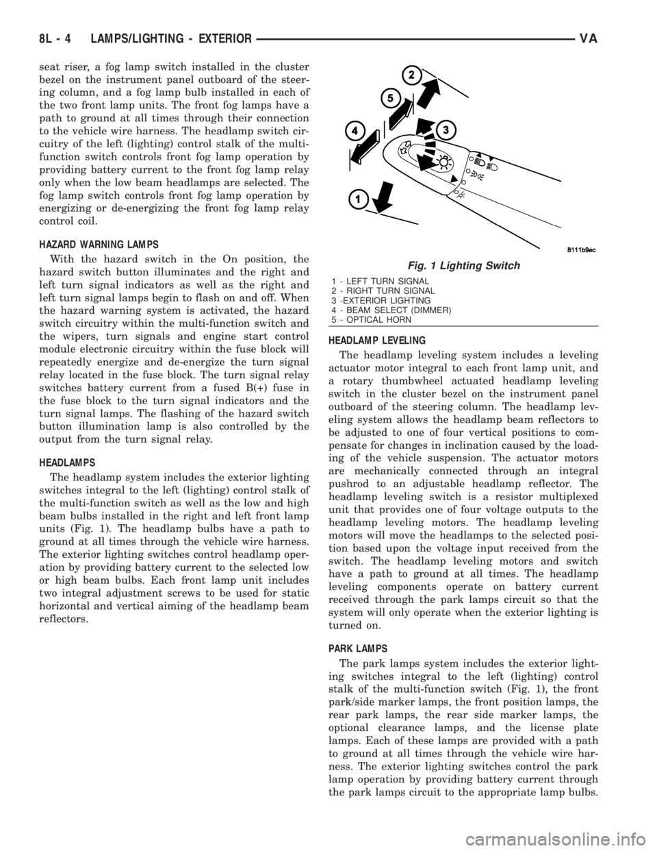
Fig. 1 Lighting Switch
1 - LEFT TURN SIGNAL
2 - RIGHT TURN SIGNAL
3 -EXTERIOR LIGHTING
4 - BEAM SELECT (DIMMER)
5 - OPTICAL HORN
8L - 4 LAMPS/LIGHTING - EXTERIORVA
Page 1092 of 2305
8W-02 COMPONENT INDEX
Component Page
A/C Auxiliary Fan..................... 8W-42
A/C Auxiliary Fan Relay................ 8W-42
A/C Compressor Clutch................. 8W-42
A/C Compressor Clutch Relay............ 8W-42
A/C Roof Auxiliary Fan................. 8W-42
A/C Roof Auxiliary Fan Relay............ 8W-42
Accelerator Pedal Position Sensor......... 8W-30
Additional Heat Exchanger.............. 8W-42
Additional Heat Exchanger Relay......... 8W-42
Additional Heat Exchanger Switch........ 8W-42
Air Outlet Temperature Sensor........... 8W-42
Airbag Control Module................. 8W-43
Airbag Squibs........................ 8W-43
Ambient Temperature Sensor............ 8W-42
Anti Icing Switch..................... 8W-42
Ash Receiver Lamp.................... 8W-44
Automatic Temperature Control Module.... 8W-42
Auxiliary Heater Control................ 8W-42
Battery............................. 8W-20
Battery Relay-Auxiliary................ 8W-20
Battery-Auxiliary..................... 8W-20
Beam Select Switch.................... 8W-50
Blower Motor Resistor Block............. 8W-42
Blower Motor-Front.................... 8W-42
Blower Stage I Diode................... 8W-42
Body Plug Connector................... 8W-11
Boost Pressure Sensor.................. 8W-30
Boost Pressure Servomotor.............. 8W-30
Boost Pressure Solenoid................ 8W-30
Brake Fluid Level Switch............... 8W-35
Brake Lamp Switch.................... 8W-35
Brake Lamp Switch 4 Pole.............. 8W-35
Brake Pressure Sensor................. 8W-35
Brake Wear Sensors................... 8W-35
CTEL Antenna Connector............... 8W-55
CTEL Connector...................... 8W-55
Cabin Heater Assembly................. 8W-42
Cabin Heater Module.................. 8W-42
Camshaft Position Sensor............... 8W-30
Center High Mounted Stop Lamp......... 8W-51
Central Timer Module.................. 8W-45
Cigar Lighter......................... 8W-41
Cigar Lighter Lamp................... 8W-44
Circulation Pump..................... 8W-42
Circulation Pump Diode................ 8W-42
Circulation Pump Relay-Cabin Heater
Module........................... 8W-42
Clockspring....................... 8W-41, 43
Controller Antilock Brake............... 8W-35
Courtesy Lamps...................... 8W-44
Crankcase Heater..................... 8W-30
Crankshaft Position Sensor.............. 8W-30Component Page
Cylinder Lock Switch-Driver............. 8W-61
D+ Relays........................ 8W-10, 11
Data Link Connector................... 8W-18
Daytime Running Lamp Relays........... 8W-50
Differential Lock Solenoid Valve.......... 8W-31
Dome Lamp.......................... 8W-44
Door Jamb Switch-Rear................. 8W-61
Door Jamb Switches................... 8W-44
Door Jamb Switches-Sliding............. 8W-61
Door Lock Motor/Ajar Switch Assemblies . . . 8W-61
Dosing Pump......................... 8W-42
EGR Valve........................... 8W-30
Electrohydraulic Control Unit............ 8W-31
Engine Control Module................. 8W-30
Engine Control Relay.................. 8W-31
Engine Coolant Level Switch............. 8W-30
Engine Coolant Temperature Sensor....... 8W-30
Engine Oil Sensor..................... 8W-30
Evaporator Temperature Sensor.......... 8W-42
Fan Stage 1 Relay..................... 8W-42
Fog Lamp Relay...................... 8W-50
Fog Lamp Switch..................... 8W-50
Fuel Injectors........................ 8W-30
Fuel Level Sensor..................... 8W-30
Fuel Pressure Sensor.................. 8W-30
Fuel Pressure Solenoid................. 8W-30
Fuel Pump........................... 8W-30
Fuel Pump Relay...................... 8W-30
Fuel Quantity Control Valve............. 8W-30
Fuel Shutdown Solenoid................ 8W-30
Fuel Temperature Sensor............... 8W-30
Fuse Blocks.................... 8W-10, 11, 30
Fuse/Relay Block...................... 8W-11
Fused Ignition Switch Run-Start Relay..... 8W-11
Fuses......................... 8W-10, 11, 42
Generator........................... 8W-20
Glow Plug Control Module.............. 8W-30
Glow Plugs.......................... 8W-30
Grounds............................ 8W-15
Hazard Warning Switch................ 8W-52
Headlamp Adjust Switch................ 8W-50
Headlamp Assemblies............... 8W-50, 52
Headlamp Switch..................... 8W-50
Heated Seat Modules.................. 8W-63
Heated Seat Switches.................. 8W-63
Heater Timer-Auxiliary................. 8W-42
High Idle Switch...................... 8W-30
High Pressure Switch.................. 8W-42
Hood Ajar Switch..................... 8W-39
Horn............................... 8W-41
Horn Relay.......................... 8W-41
Horn Switch......................... 8W-41
VA8W-02 COMPONENT INDEX 8W - 02 - 1
Page 1581 of 2305
(6) Remove the turbocharger heat shield (Fig. 3).
(7) Remove the engine cover (Fig. 3).
(8) Remove the air cleaner and hose at the turbo-
charger and air cleaner assembly.
(9) Disconnect the transmission lines at the radia-
tor.
(10) Disconnect the upper and lower radiator
hoses.
(11) Disconnect the A/C lines at the condenser.
(12) Disconnect the condenser fan harness connec-
tor.
(13) Disconnect the power steering cooler lines at
the cooler.
(14) Disconnect the charge air cooler hose at the
intake manifold (Fig. 3).
(15) Remove charge air hose fasteners at the radi-
ator closure panel.
(16) Remove the fasteners retaining the radiator to
the front crossmember.(17) Remove the change air cooler, A/C conderser
and fan as an assembly.
(18) Disconnect the charge air hose at the intake
manifold (Fig. 3).
(19) Remove the radiator assembly.
(20) Disconnect the high pressure and return
hoses at the power steering pump.
(21) Disconnect the fuel lines at the fuel filter.
(22) Disconnect the refrigerant line at the A/C
compressor.
(23) Disconnect the vacuum line for the brake
booster at the vacuum pump (Fig. 3).
(24) Disconnect the coolant hose of heating return
flow at the water pump.
(25) Disconnect the coolant hose of the heater sup-
ply at the coolant pipe at the side of the cylinder
head.
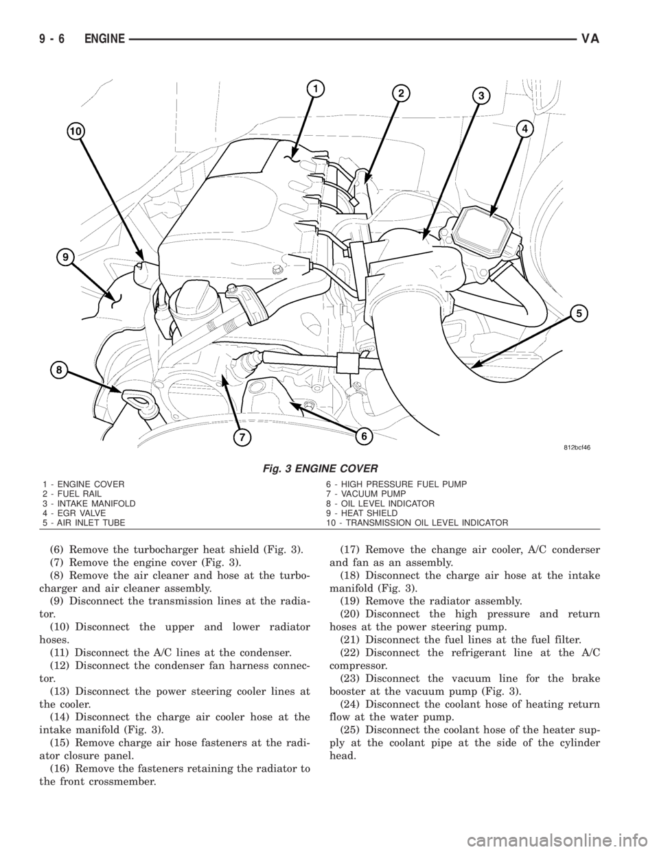
Fig. 3 ENGINE COVER
1 - ENGINE COVER 6 - HIGH PRESSURE FUEL PUMP
2 - FUEL RAIL 7 - VACUUM PUMP
3 - INTAKE MANIFOLD 8 - OIL LEVEL INDICATOR
4 - EGR VALVE 9 - HEAT SHIELD
5 - AIR INLET TUBE 10 - TRANSMISSION OIL LEVEL INDICATOR
9 - 6 ENGINEVA