2006 MERCEDES-BENZ SPRINTER coolant reservoir
[x] Cancel search: coolant reservoirPage 2085 of 2305

(5) Remove the shift mechanism (Refer to 21 -
TRANSMISSION/TRANSAXLE/AUTOMATIC -
NAG1/SHIFT MECHANISM - REMOVAL).
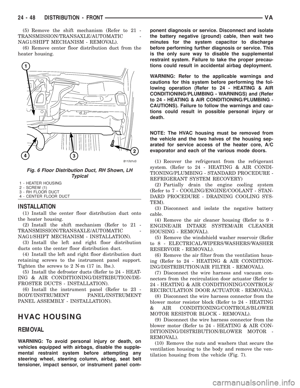
(6) Remove center floor distribution duct from the
heater housing.
INSTALLATION
(1) Install the center floor distribution duct onto
the heater housing.
(2) Install the shift mechanism (Refer to 21 -
TRANSMISSION/TRANSAXLE/AUTOMATIC -
NAG1/SHIFT MECHANISM - INSTALLATION).
(3) Install the left and right floor distribution
ducts onto the center floor distribution duct.
(4) Install the left and right floor distribution duct
retaining screws to the instrument panel support.
Tighten the screws to 2 N´m (17 in. lbs.).
(5) Install the defroster ducts (Refer to 24 - HEAT-
ING & AIR CONDITIONING/DISTRIBUTION/DE-
FROSTER DUCTS - INSTALLATION).
(6) Install the instrument panel (Refer to 23 -
BODY/INSTRUMENT PANEL/INSTRUMENT
PANEL ASSEMBLY - INSTALLATION).
HVAC HOUSING
REMOVAL
WARNING: To avoid personal injury or death, on
vehicles equipped with airbags, disable the supple-
mental restraint system before attempting any
steering wheel, steering column, airbag, seat belt
tensioner, impact sensor, or instrument panel com-ponent diagnosis or service. Disconnect and isolate
the battery negative (ground) cable, then wait two
minutes for the system capacitor to discharge
before performing further diagnosis or service. This
is the only sure way to disable the supplemental
restraint system. Failure to take the proper precau-
tions could result in accidental airbag deployment.
WARNING: Refer to the applicable warnings and
cautions for this system before performing the fol-
lowing operation (Refer to 24 - HEATING & AIR
CONDITIONING/PLUMBING - WARNINGS) and (Refer
to 24 - HEATING & AIR CONDITIONING/PLUMBING -
CAUTIONS). Failure to follow the warnings and cau-
tions could result in possible personal injury or
death.
NOTE: The HVAC housing must be removed from
the vehicle and the two halves of the housing sep-
arated for service access of the heater core, A/C
evaporator and each of the various mode doors.
(1) Recover the refrigerant from the refrigerant
system. (Refer to 24 - HEATING & AIR CONDI-
TIONING/PLUMBING - STANDARD PROCEDURE -
REFRIGERANT SYSTEM RECOVERY)
(2) Partially drain the engine cooling system
(Refer to 7 - COOLING/ENGINE/COOLANT - STAN-
DARD PROCEDURE - DRAINING COOLING SYS-
TEM).
(3) Disconnect and isolate the negative battery
cable.
(4) Remove the air cleaner housing (Refer to 9 -
ENGINE/AIR INTAKE SYSTEM/AIR CLEANER
HOUSING - REMOVAL).
(5) Remove the windshield washer reservoir (Refer
to 8 - ELECTRICAL/WIPERS/WASHERS/WASHER
RESERVOIR - REMOVAL).
(6) Remove the air filter from the ventilation hous-
ing (Refer to 24 - HEATING & AIR CONDITION-
ING/DISTRIBUTION/AIR FILTER - REMOVAL).
(7) Disconnect the wire harness and vacuum con-
nectors from the recirculation door actuator (Refer to
24 - HEATING & AIR CONDITIONING/CONTROLS/
RECIRCULATION DOOR ACTUATOR - REMOVAL).
(8) Disconnect the wire harness connector from the
blower motor resistor block (Refer to 24 - HEATING
& AIR CONDITIONING/CONTROLS/BLOWER
MOTOR RESISTOR BLOCK - REMOVAL).
(9) Disconnect the wire harness connector from the
blower motor (Refer to 24 - HEATING & AIR CON-
DITIONING/DISTRIBUTION/BLOWER MOTOR -
REMOVAL).
(10) Remove the nuts and washers that secure the
ventilation housing to the body and remove the ven-
tilation housing from the vehicle (Fig. 7).
Fig. 6 Floor Distribution Duct, RH Shown, LH
Typical
1 - HEATER HOUSING
2 - SCREW (1)
3 - RH FLOOR DUCT
4 - CENTER FLOOR DUCT
24 - 48 DISTRIBUTION - FRONTVA
Page 2088 of 2305

(12) Install the two bolts that secure the refriger-
ant line terminal block to the A/C evaporator.
Tighten the bolts to 5 N´m (45 in. lbs.).
(13) Unplug or remove the tape from the heater
core hoses and tubes.
(14) Connect the heater hoses to the heater core
tubes and install the heater hose clamps.
(15) Install the ventilation housing to the dash
panel.
(16) Install the nuts and washers that secure the
ventilation housing to the dash panel. Tighten the
nuts to 5 N´m (45 in. lbs.).
(17) Connect the wire harness connectors to the
blower motor, blower motor resistor block and the
recirculation door actuator.
(18) Connect the vacuum harness connector to the
recirculation door actuator.
(19) Install the air filter into the ventilation hous-
ing (Refer to 24 - HEATING & AIR CONDITION-
ING/DISTRIBUTION/AIR FILTER -
INSTALLATION).
(20) Install the windshield washer reservoir (Refer
to 8 - ELECTRICAL/WIPERS/WASHERS/WASHER
RESERVOIR - INSTALLATION).
(21) Install the air cleaner housing (Refer to 9 -
ENGINE/AIR INTAKE SYSTEM/AIR CLEANER
HOUSING - INSTALLATION).
(22) Reconnect the negative battery cable.
(23) If the heater core is being replaced, flush the
cooling system (Refer to 7 - COOLING - STANDARD
PROCEDURE - COOLING SYSTEM CLEANING/
REVERSE FLUSHING).
(24) Refill the engine cooling system (Refer to 7 -
COOLING/ENGINE/COOLANT - STANDARD PRO-
CEDURE - COOLANT SYSTEM FILL).
(25) Evacuate the refrigerant system (Refer to 24 -
HEATING & AIR CONDITIONING/PLUMBING -
STANDARD PROCEDURE - REFRIGERANT SYS-
TEM EVACUATE).
(26) Charge the refrigerant system (Refer to 24 -
HEATING & AIR CONDITIONING/PLUMBING -
STANDARD PROCEDURE - REFRIGERANT SYS-
TEM CHARGE).
INSTRUMENT PANEL DUCTS
REMOVAL
(1) Remove the instrument panel (Refer to 23 -
BODY/INSTRUMENT PANEL/INSTRUMENT
PANEL ASSEMBLY - REMOVAL).
(2) Remove the defroster ducts (Refer to 24 -
HEATING & AIR CONDITIONING/DISTRIBUTION/
DEFROSTER DUCTS - REMOVAL).
(3) Remove the floor distribution ducts (Refer to 24
- HEATING & AIR CONDITIONING/DISTRIBU-
TION/FLOOR DISTRIBUTION DUCTS -
REMOVAL).(4) If removing the right instrument panel duct,
remove the passenger air bag module and bracket
(Refer to 8 - ELECTRICAL/RESTRAINTS/PASSEN-
GER AIRBAG - REMOVAL).
(5) Remove the screws that secure the left and/or
right instrument panel duct and remove the duct(s)
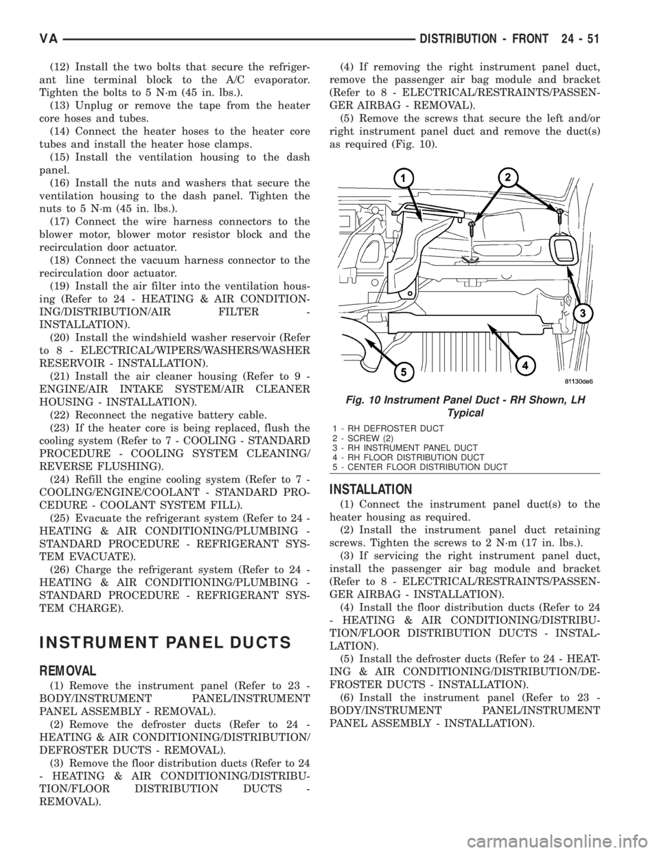
as required (Fig. 10).
INSTALLATION
(1) Connect the instrument panel duct(s) to the
heater housing as required.
(2) Install the instrument panel duct retaining
screws. Tighten the screws to 2 N´m (17 in. lbs.).
(3) If servicing the right instrument panel duct,
install the passenger air bag module and bracket
(Refer to 8 - ELECTRICAL/RESTRAINTS/PASSEN-
GER AIRBAG - INSTALLATION).
(4) Install the floor distribution ducts (Refer to 24
- HEATING & AIR CONDITIONING/DISTRIBU-
TION/FLOOR DISTRIBUTION DUCTS - INSTAL-
LATION).
(5) Install the defroster ducts (Refer to 24 - HEAT-
ING & AIR CONDITIONING/DISTRIBUTION/DE-
FROSTER DUCTS - INSTALLATION).
(6) Install the instrument panel (Refer to 23 -
BODY/INSTRUMENT PANEL/INSTRUMENT
PANEL ASSEMBLY - INSTALLATION).
Fig. 10 Instrument Panel Duct - RH Shown, LH
Typical
1 - RH DEFROSTER DUCT
2 - SCREW (2)
3 - RH INSTRUMENT PANEL DUCT
4 - RH FLOOR DISTRIBUTION DUCT
5 - CENTER FLOOR DISTRIBUTION DUCT
VADISTRIBUTION - FRONT 24 - 51
Page 2098 of 2305

REAR REFRIGERANT RESERVOIR
REMOVAL.............................95
INSTALLATION.........................95
REAR SUCTION LINE
DESCRIPTION.........................96
REMOVAL.............................96
INSTALLATION.........................98
REFRIGERANT LINE COUPLER
DESCRIPTION.........................98OPERATION...........................98
REMOVAL.............................99
INSTALLATION.........................99
UNDERBODY LINES
REMOVAL............................100
INSTALLATION........................102
PLUMBING
DESCRIPTION
The refrigerant lines and hoses are used to carry
the refrigerant between the various air conditioning
system components. A barrier hose design with a
nylon tube, which is sandwiched between rubber lay-
ers, is used for the R-134a air conditioning system on
this vehicle. This nylon tube helps to further contain
the R-134a refrigerant, which has a smaller molecu-
lar structure than R-12 refrigerant. The ends of the
refrigerant hoses are made from lightweight alumi-
num or steel, and commonly use braze-less fittings.
Any kinks or sharp bends in the refrigerant plumb-
ing will reduce the capacity of the entire air condi-
tioning system. Kinks and sharp bends reduce the
flow of refrigerant in the system. A good rule for the
flexible hose refrigerant lines is to keep the radius of
all bends at least ten times the diameter of the hose.
In addition, the flexible hose refrigerant lines should
be routed so they are at least 80 millimeters (3
inches) from the exhaust manifold.
OPERATION
High pressures are produced in the refrigerant sys-
tem when the air conditioning compressor is operat-
ing. Extreme care must be exercised to make sure
that each of the refrigerant system connections is
pressure-tight and leak free. It is a good practice to
inspect all flexible hose refrigerant lines at least once
a year to make sure they are in good condition and
properly routed.
The refrigerant lines and hoses cannot be repaired
and, if faulty or damaged, they must be replaced.
WARNINGS
WARNING: The A/C system contains refrigerant
under high pressure. Repairs should only be per-
formed by qualified service personnel. Severe per-
sonal injury or death may result from improper
service procedures.
WARNING: Avoid breathing the refrigerant and
refrigerant oil vapor or mist. Exposure may irritate
the eyes, nose, and/or throat. Wear eye protectionwhen servicing the A/C refrigerant system. Serious
eye injury can result from direct contact with the
refrigerant. If eye contact occurs, seek medical
attention immediately.
WARNING: Do not expose the refrigerant to open
flame. Poisonous gas is created when refrigerant is
burned. An electronic leak detector is recom-
mended. Severe personal injury or death may result
from improper service procedures.
WARNING: If accidental system discharge occurs,
ventilate the work area before resuming service.
Large amounts of refrigerant released in a closed
work area will displace the oxygen and cause suf-
focation and death.
WARNING: The evaporation rate of R-134a refriger-
ant at average temperature and altitude is extremely
high. As a result, anything that comes in contact
with the refrigerant will freeze. Always protect the
skin or delicate objects from direct contact with the
refrigerant.
WARNING: The R-134a service equipment or the
vehicle refrigerant system should not be pressure
tested or leak tested with compressed air. Some
mixtures of air and R-134a have been shown to be
combustible at elevated pressures. These mixtures
are potentially dangerous, and may result in fire or
explosion causing property damage, personal injury
or death.
WARNING: The engine cooling system is designed
to develop internal pressures of 97 to 123 kilopas-
cals (14 to 18 pounds per square inch). Do not
remove or loosen the coolant pressure cap, cylin-
der block drain plugs, radiator drain, radiator
hoses, heater hoses, or hose clamps while the
engine cooling system is hot and under pressure.
Allow the vehicle to cool for a minimum of 15 min-
utes before opening the cooling system for service.
Failure to observe this warning can result in seri-
ous burns from the heated engine coolant.
VAPLUMBING 24 - 61
Page 2158 of 2305

INDEX
ABS INDICATOR.......................8J-9ACCELERATOR PEDAL POSITION SENSOR. . . 14-32
ACCESSORY SWITCH BEZEL............23-56
ADR INDICATOR.....................8J-10
AIR CLEANER ELEMENT................9-21
AIR CLEANER HOUSING................9-21
AIR FILTER ....................24-45, 24-58
AIR OUTLET TEMPERATURE SENSOR....24-16
AIR OUTLETS.......................24-45
AIRBAG CONTROL MODULE.............8O-8
AIRBAG INDICATOR...................8J-11
ALB CONTROLLER....................5-16
ALB LEVER..........................5-16
AMBIENT TEMPERATURE INDICATOR.....8J-11
AMBIENT TEMPERATURE SENSOR.......24-17
ANTENNA BODY & CABLE..............8A-1
ARMREST..........................23-79
ASH RECEIVER......................23-57
ASH RECEIVER / CIGAR LIGHTER LAMP
UNIT..............................8L-30
ASSIST HANDLE.....................23-71
AUDIO..............................8A-1
AUTOMATIC TRANSMISSION NAG1 -
SERVICE INFORMATION................21-3
A - PILLAR TRIM.....................23-70
A / C CLUTCH RELAY.................24-24
A / C COMPRESSOR CLUTCH COIL.......24-12
A / C COMPRESSOR CLUTCH............24-8
A / C COMPRESSOR..................24-66
A / C CONDENSER COVER.............24-52
A / C CONDENSER FAN RELAY..........24-26
A / C CONDENSER HOUSING...........24-52
A / C CONDENSER....................24-69
A / C CONTROL MODULE..............24-28
A / C DISCHARGE LINE................24-71
A / C EVAPORATOR COVER.............24-55
A / C EVAPORATOR HOUSING...........24-55
A / C EVAPORATOR...................24-72
A / C EXPANSION VALVE...............24-73
A / C HEATER CONTROL...............24-12
A / C HIGH PRESSURE SWITCH.........24-30
A / C LOW PRESSURE SWITCH.........24-32
A / C PRESSURE TRANSDUCER.........24-14
BACKLITE - BULKHEAD TRIM PANEL.....23-84
BACKUP LAMP BULB..................8L-5
BASECOAT / CLEARCOAT FINISH........23-77
BATTERY CABLES....................8F-14
BATTERY HOLDDOWN.................8F-13
BATTERY SYSTEM.....................8F-1
BATTERY TRAY......................8F-16
BATTERY............................8F-6
BEARINGS - DIFFERENTIAL CASE.........3-38
BEARING / SEAL - AXLE HUB............3-28
BEARING / SEAL - AXLE................3-24
BELT TENSIONERS.....................7-5
BLOWER MOTOR RELAY...............24-33
BLOWER MOTOR RESISTOR............24-17
BLOWER MOTOR SWITCH........24-19, 24-35
BLOWER MOTOR...............24-47, 24-58
BODY...............................23-1
BOOST PRESSURE SENSOR............14-33
BRAKE INDICATOR...................8J-12
BRAKE LAMP SWITCH.................8L-6
BRAKE LINES.........................5-8
BRAKE PADS / SHOES...................5-8
BRAKE WEAR INDICATOR..............8J-13
BRAKES - ABS........................5-30
BRAKES - BASE........................5-2
BRAKE / PARK LAMP BULB.............8L-7
BULKHEAD TRIM PANEL...............23-72
BUMPERS...........................13-1
BUSHINGS............................2-3
B - PILLAR TRIM.....................23-71
CABIN HEATER.....................24-104
CABLE TENSIONER....................5-24
CABLE..............................8P-2
CABLES.............................5-24
CAMSHAFT POSITION SENSOR..........14-33
CAMSHAFT(S)........................9-28
CARGO LAMP SWITCH................8L-31
CARGO / DOME LAMP BULB............8L-30
CARGO / DOME LAMP UNIT............8L-31
CARPETS AND FLOOR MATS...........23-72
CATALYTIC CONVERTER
................11-3
CENTER BEARING
......................3-9
CENTER HIGH MOUNTED STOP LAMP BULB. . . 8L-8CENTER HIGH MOUNTED STOP LAMP UN.....8L-8
CENTER ROLLER ARM
................23-36CENTER TRACK......................23-37
CENTRAL TIMER MODULE..............8E-1
CHARGE AIR COOLER AND PLUMBING....11-4
CHARGING INDICATOR................8J-14
CHARGING SYSTEM..................8F-17
CHECK VALVE.......................8R-11
CHECK.......................23-13, 23-23
CHIME / BUZZER......................8B-1
CIGAR LIGHTER OUTLET............8W-97-1
CIRCUIT BREAKER.................8W-97-2
CLEARANCE LAMP BULB...............8L-9
CLEARANCE LAMP UNIT................8L-9
CLOCK.............................8J-14
CLOCKSPRING......................8O-12
CLUSTER BEZEL.....................23-55
COLUMN............................19-4
CONNECTOR.......................Intro.-9
CONNECTOR/GROUND/SPLICE
LOCATION........................8W-91-1
CONTROLLER ANTILOCK BRAKE.........8E-3
COOLANT LEVEL SENSOR...............7-13
COOLANT LOW INDICATOR.............8J-15
COOLANT............................7-9
COOLING.............................7-1
COWL TRIM........................23-73
CRANKCASE VENTILATION BREATHER......25-2
CRANKCASE VENTILATION HEATER.......25-1
CRANKSHAFT OIL SEAL - FRONT.........9-42
CRANKSHAFT OIL SEAL - REAR..........9-41
CRANKSHAFT POSITION SENSOR........14-35
CRANKSHAFT........................9-39
CUP HOLDER........................23-57
CYLINDER HEAD COVER(S).............9-33
CYLINDER HEAD......................9-22
DAYTIME RUNNING LAMP RELAY.......8L-10
DEFROSTER DUCTS..................24-47
DIFFERENTIAL........................3-31
DIODE............................Intro.-9
DISC BRAKE CALIPER ADAPTER.........5-14
DISC BRAKE CALIPERS.................5-11
DOME LAMP / INTRUSION SENSOR
BULB..............................8L-33
DOME LAMP / INTRUSION SENSOR......8L-33
DOME / READING LAMP BULB..........8L-32
DOME / READING LAMP UNIT..........8L-32
DOOR GLASS............23-15, 23-30, 23-46
DOOR JAMB SWITCH.................8L-34
DOOR LOCK MOTOR...................8N-1
DOOR OPENING SEALS................23-90
DOOR........................23-14, 23-23
DRIVE BELTS..........................7-5
DRIVER AIRBAG.....................8O-16
DRIVER HEATED SEAT SWITCH.........8G-11
D - PILLAR TRIM.....................23-73
ELECTRIC COOLANT PUMP.............24-75
ELECTRICAL.........................5-30
ELECTROHYDRAULIC UNIT............21-105
ENGINE BLOCK HEATER................7-14
ENGINE BLOCK.......................9-37
ENGINE CONTROL MODULE.............8E-3
ENGINE COOLANT TEMP SENSOR........7-15
ENGINE COOLANT THERMOSTAT.........7-16
ENGINE CRADLE CROSSMEMBER........13-8
ENGINE TEMPERATURE GAUGE.........8J-15
ENGINE..............................9-2
ENTRY / EXIT LAMP BULB.............8L-34
ENTRY / EXIT LAMP UNIT..............8L-35
ESP INDICATOR......................8J-16
EVAPORATOR TEMPERATURE
SENSOR......................24-19, 24-37
EXHAUST GAS RECIRCULATION..........25-4
EXHAUST MANIFOLD..................9-68
EXHAUST PIPE.......................11-3
EXHAUST SYSTEM....................11-1
EXHAUST TUBE.....................24-105
EXTERIOR HANDLE.......23-16, 23-31, 23-35
FAN DRIVE VISCOUS CLUTCH...........7-17
FASTENER IDENTIFICATION...........Intro.-3
FASTENER USAGE...................Intro.-6
FINESSE SANDING / BUFFING & POLISH . . 23-78
FLOOR DISTRIBUTION DUCTS..........24-47
FLUID AND FILTER..................21-131
FLUID CAPACITIES.....................0-5
FLUID COOLER TUBE
.................19-13
FLUID FILL / CHECK LOCATIONS
..........0-5
FLUID RESERVOIR
....................5-15
FLUID TYPES
..........................0-1
FLYWHEEL
...........................9-43FOG LAMP BULB.....................8L-10
FOG LAMP RELAY....................8L-11
FOG LAMP SWITCH...................8L-12
FRAME..............................13-3
FREEWHEELING CLUTCH.............21-135
FRONT BUMPER - STEPS...............13-2
FRONT DOOR INNER BELT
WEATHERSTRIP.....................23-90
FRONT DOOR OUTER BELT
WEATHERSTRIP.....................23-90
FRONT FASCIA.......................13-2
FRONT LAMP UNIT...................8L-13
FRONT POSITION LAMP BULB..........8L-14
FRONT SEAT BELT & RETRACTOR.......8O-20
FRONT SEAT BELT BUCKLE............8O-23
FRONT TURN / PARK / SIDE MARKER
LAMP BULB.........................8L-15
FRONT WHEEL SPEED SENSOR..........5-31
FRONT...............................2-1
FUEL DELIVERY.......................14-6
FUEL DOSING PUMP.................24-106
FUEL DRAIN TUBES..................14-10
FUEL FILL DOOR.....................23-48
FUEL FILTER CLOGGED INDICATOR......8J-17
FUEL FILTER........................14-10
FUEL GAUGE........................8J-17
FUEL INJECTOR.......................14-35
FUEL LEVEL SENDING UNIT / SENSOR....14-28
FUEL LINE.........................24-107
FUEL LINES.........................14-11
FUEL PRESSURE SENSOR.............14-39
FUEL PRESSURE SOLENOID............14-40
FUEL PUMP MODULE.................14-18
FUEL PUMP.........................14-13
FUEL QUANTITY CONTROL VALVE.......14-21
FUEL RAIL PRESSURE SENSOR.........14-12
FUEL RAIL..........................14-22
FUEL SYSTEM........................14-1
FUEL TANK.........................14-23
FUEL TEMPERATURE SENSOR..........14-42
FUSE BLOCK #1...................8W-97-2
FUSE BLOCK #2...................8W-97-3
GAP AND FLUSH.....................23-91
GEAR SELECTOR INDICATOR...........8J-18
GEAR...............................19-7
GEARSHIFT CABLE..................21-138
GEAR - PINION / RING.................3-41
GENERATOR DECOUPLER PULLEY.......8F-19
GENERATOR........................8F-18
GLOVE BOX.........................23-58
GLOW PLUG RELAY....................8I-1
GLOW PLUG..........................8I-1
GRILLE............................23-48
HCU (HYDRAULIC CONTROL UNIT).......5-36
HEADLAMP LEVELING MOTOR..........8L-16
HEADLAMP LEVELING SWITCH.........8L-17
HEADLINER.........................23-73
HEADREST..........................23-79
HEATED GLASS.......................8G-1
HEATED MIRRORS....................8G-9
HEATED SEAT ELEMENT...............8G-12
HEATED SEAT RELAY.................8G-12
HEATED SEAT SENSOR................8G-13
HEATED SEATS ......................8G-10
HEATER CORE.......................24-76
HEATER UNIT......................24-110
HEATING & AIR CONDITIONING..........24-1
HIGH BEAM HEADLAMP BULB..........8L-18
HIGH BEAM INDICATOR...............8J-19
HINGE..................23-17, 23-32, 23-51
HOISTING............................0-5
HOLDING CLUTCH B1................21-143
HOLDING CLUTCH B2................21-148
HOLDING CLUTCHES.................21-141
HOOD.............................23-51
HORN SWITCH.......................8H-1
HORN..............................8H-1
HOSES.............................19-14
HUB / BEARING........................2-4
HVAC HOUSING......................24-48
HYDRAULIC / MECHANICAL..............5-5
IGNITION CONTROL....................8I-1
INLET HOSE........................24-111
INPUT CLUTCH K1
...................21-92
INPUT CLUTCH K2
...................21-97
INPUT CLUTCH K3
..................21-102
INPUT CLUTCHES
....................21-90
INPUT SPEED SENSORS
..............21-153
VAINDEX 1
Description Group-Page Description Group-Page Description Group-Page