2006 MERCEDES-BENZ SPRINTER brake rotor
[x] Cancel search: brake rotorPage 794 of 2305
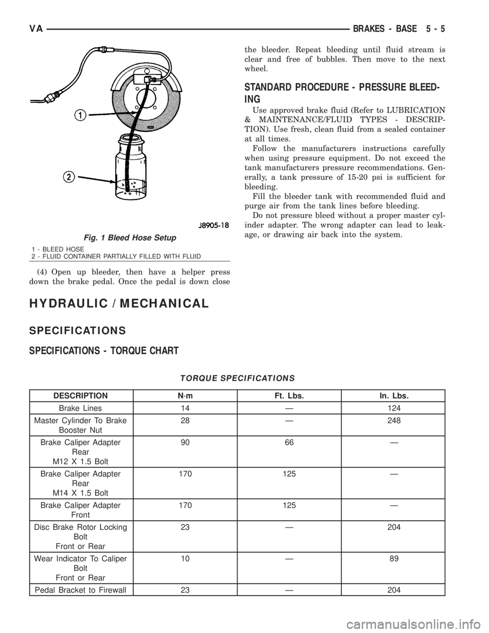
(4) Open up bleeder, then have a helper press
down the brake pedal. Once the pedal is down closethe bleeder. Repeat bleeding until fluid stream is
clear and free of bubbles. Then move to the next
wheel.
STANDARD PROCEDURE - PRESSURE BLEED-
ING
Use approved brake fluid (Refer to LUBRICATION
& MAINTENANCE/FLUID TYPES - DESCRIP-
TION). Use fresh, clean fluid from a sealed container
at all times.
Follow the manufacturers instructions carefully
when using pressure equipment. Do not exceed the
tank manufacturers pressure recommendations. Gen-
erally, a tank pressure of 15-20 psi is sufficient for
bleeding.
Fill the bleeder tank with recommended fluid and
purge air from the tank lines before bleeding.
Do not pressure bleed without a proper master cyl-
inder adapter. The wrong adapter can lead to leak-
age, or drawing air back into the system.
HYDRAULIC / MECHANICAL
SPECIFICATIONS
SPECIFICATIONS - TORQUE CHART
TORQUE SPECIFICATIONS
DESCRIPTION N´m Ft. Lbs. In. Lbs.
Brake Lines 14 Ð 124
Master Cylinder To Brake
Booster Nut28 Ð 248
Brake Caliper Adapter
Rear
M12 X 1.5 Bolt90 66 Ð
Brake Caliper Adapter
Rear
M14 X 1.5 Bolt170 125 Ð
Brake Caliper Adapter
Front170 125 Ð
Disc Brake Rotor Locking
Bolt
Front or Rear23 Ð 204
Wear Indicator To Caliper
Bolt
Front or Rear10 Ð 89
Pedal Bracket to Firewall 23 Ð 204
Fig. 1 Bleed Hose Setup
1 - BLEED HOSE
2 - FLUID CONTAINER PARTIALLY FILLED WITH FLUID
VABRAKES - BASE 5 - 5
Page 795 of 2305
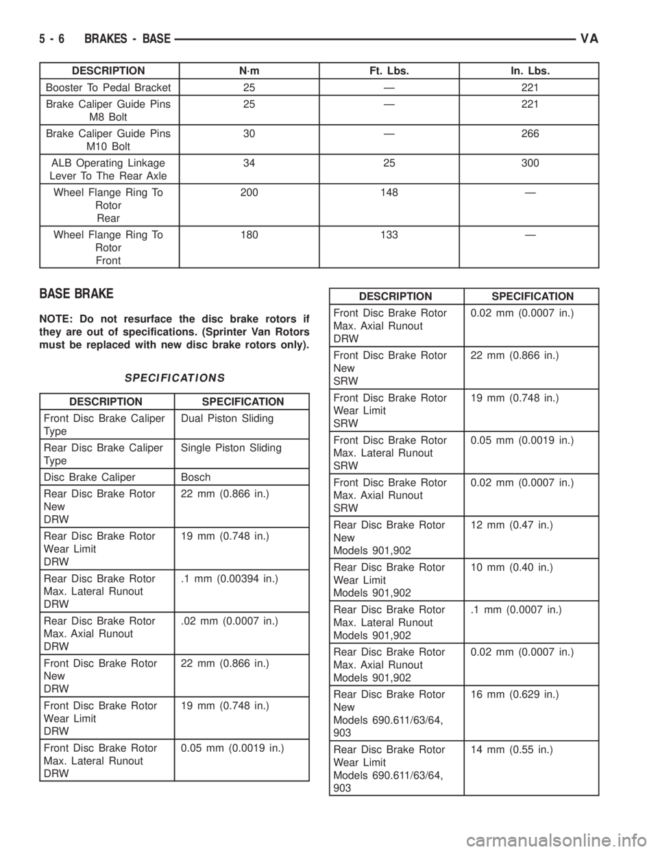
DESCRIPTION N´m Ft. Lbs. In. Lbs.
Booster To Pedal Bracket 25 Ð 221
Brake Caliper Guide Pins
M8 Bolt25 Ð 221
Brake Caliper Guide Pins
M10 Bolt30 Ð 266
ALB Operating Linkage
Lever To The Rear Axle34 25 300
Wheel Flange Ring To
Rotor
Rear200 148 Ð
Wheel Flange Ring To
Rotor
Front180 133 Ð
BASE BRAKE
NOTE: Do not resurface the disc brake rotors if
they are out of specifications. (Sprinter Van Rotors
must be replaced with new disc brake rotors only).
SPECIFICATIONS
DESCRIPTION SPECIFICATION
Front Disc Brake Caliper
TypeDual Piston Sliding
Rear Disc Brake Caliper
TypeSingle Piston Sliding
Disc Brake Caliper Bosch
Rear Disc Brake Rotor
New
DRW22 mm (0.866 in.)
Rear Disc Brake Rotor
Wear Limit
DRW19 mm (0.748 in.)
Rear Disc Brake Rotor
Max. Lateral Runout
DRW.1 mm (0.00394 in.)
Rear Disc Brake Rotor
Max. Axial Runout
DRW.02 mm (0.0007 in.)
Front Disc Brake Rotor
New
DRW22 mm (0.866 in.)
Front Disc Brake Rotor
Wear Limit
DRW19 mm (0.748 in.)
Front Disc Brake Rotor
Max. Lateral Runout
DRW0.05 mm (0.0019 in.)
DESCRIPTION SPECIFICATION
Front Disc Brake Rotor
Max. Axial Runout
DRW0.02 mm (0.0007 in.)
Front Disc Brake Rotor
New
SRW22 mm (0.866 in.)
Front Disc Brake Rotor
Wear Limit
SRW19 mm (0.748 in.)
Front Disc Brake Rotor
Max. Lateral Runout
SRW0.05 mm (0.0019 in.)
Front Disc Brake Rotor
Max. Axial Runout
SRW0.02 mm (0.0007 in.)
Rear Disc Brake Rotor
New
Models 901,90212 mm (0.47 in.)
Rear Disc Brake Rotor
Wear Limit
Models 901,90210 mm (0.40 in.)
Rear Disc Brake Rotor
Max. Lateral Runout
Models 901,902.1 mm (0.0007 in.)
Rear Disc Brake Rotor
Max. Axial Runout
Models 901,9020.02 mm (0.0007 in.)
Rear Disc Brake Rotor
New
Models 690.611/63/64,
90316 mm (0.629 in.)
Rear Disc Brake Rotor
Wear Limit
Models 690.611/63/64,
90314 mm (0.55 in.)
5 - 6 BRAKES - BASEVA
Page 796 of 2305
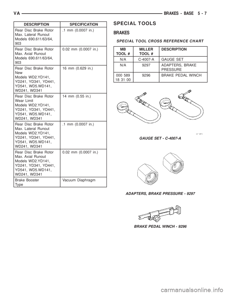
DESCRIPTION SPECIFICATION
Rear Disc Brake Rotor
Max. Lateral Runout
Models 690.611/63/64,
903.1 mm (0.0007 in.)
Rear Disc Brake Rotor
Max. Axial Runout
Models 690.611/63/64,
9030.02 mm (0.0007 in.)
Rear Disc Brake Rotor
New
Models WD2.YD141,
YD241, YD341, YD441,
YD541, WD5.WD141,
WD241, WD34116 mm (0.629 in.)
Rear Disc Brake Rotor
Wear Limit
Models WD2.YD141,
YD241, YD341, YD441,
YD541, WD5.WD141,
WD241, WD34114 mm (0.55 in.)
Rear Disc Brake Rotor
Max. Lateral Runout
Models WD2.YD141,
YD241, YD341, YD441,
YD541, WD5.WD141,
WD241, WD341.1 mm (0.0007 in.)
Rear Disc Brake Rotor
Max. Axial Runout
Models WD2.YD141,
YD241, YD341, YD441,
YD541, WD5.WD141,
WD241, WD3410.02 mm (0.0007 in.)
Brake Booster
TypeVacuum DiaphragmSPECIAL TOOLS
BRAKES
SPECIAL TOOL CROSS REFERENCE CHART
MB
TOOL #MILLER
TOOL #DESCRIPTION
N/A C-4007-A GAUGE SET
N/A 9297 ADAPTERS, BRAKE
PRESSURE
000 589
18 31 009296 BRAKE PEDAL WINCH
GAUGE SET - C-4007-A
ADAPTERS, BRAKE PRESSURE - 9297
BRAKE PEDAL WINCH - 9296
VABRAKES - BASE 5 - 7
Page 809 of 2305
edge of the diaphragm is secured to the housing. The
booster push rod, which connects the booster to the
brake pedal and master cylinder, is attached to the
center of the diaphragm. A check valve is used in the
booster outlet connected to the engine intake mani-
fold. Power assist is generated by utilizing a combi-
nation of vacuum and atmospheric pressure to boost
brake assist.
REMOVAL
(1) Using a suction gun remove as much brake
fluid from the reservoir as possible.
(2) Disconnect the brake level switch electrical
connector.
(3) Remove the brake lines from the master cylin-
derSeal off the ends and bore holes with plugs.
(4) Remove the master cylinder from the booster.
(5) Remove the booster vacuum hose and check
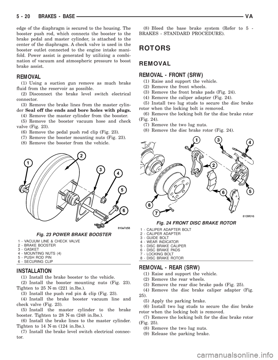
valve (Fig. 23).
(6) Remove the pedal push rod clip (Fig. 23).
(7) Remove the booster mounting nuts (Fig. 23).
(8) Remove the booster from the vehicle.
INSTALLATION
(1) Install the brake booster to the vehicle.
(2) Install the booster mounting nuts (Fig. 23).
Tighten to 25 N´m (221 in.lbs.).
(3) Install the push rod pin & clip (Fig. 23).
(4) Install the brake booster vacuum line and
check valve (Fig. 23).
(5) Install the master cylinder to the brake
booster. Tighten to 28 N´m (248 in.lbs.).
(6) Install the brake lines to the master cylinder.
Tighten to 14 N´m (124 in.lbs.).
(7) Install the brake level switch electrical connec-
tor.(8) Bleed the base brake system (Refer to 5 -
BRAKES - STANDARD PROCEDURE).
ROTORS
REMOVAL
REMOVAL - FRONT (SRW)
(1) Raise and support the vehicle.
(2) Remove the front wheels.
(3) Remove the front brake pads (Fig. 24).
(4) Remove the caliper adapter (Fig. 24).
(5) Install two lug studs to secure the disc brake
rotor when the locking bolt is removed.
(6) Remove the locking bolt for the disc brake rotor
(Fig. 24).
(7) Remove the two lug nuts.
(8) Remove the disc brake rotor (Fig. 24).
REMOVAL - REAR (SRW)
(1) Raise and support the vehicle.
(2) Remove the rear wheels.
(3) Remove the rear disc brake pads (Fig. 25).
(4) Remove the disc brake caliper adapter (Fig.
25).
(5) Apply the parking brake.
(6) Install two lug studs to secure the disc brake
rotor when the locking bolt is removed.
(7) Remove the locking bolt for the disc brake rotor
(Fig. 25).
(8) Remove the two lug nuts.
(9) Release the parking brake.
Fig. 23 POWER BRAKE BOOSTER
1 - VACUUM LINE & CHECK VALVE
2 - BRAKE BOOSTER
3 - GASKET
4 - MOUNTING NUTS (4)
5 - PUSH ROD PIN
6 - SECURING CLIP
Fig. 24 FRONT DISC BRAKE ROTOR
1 - CALIPER ADAPTER BOLT
2 - CALIPER ADAPTER
3 - GUIDE BOLT
4 - WEAR INDICATOR
5 - DISC BRAKE CALIPER
6 - DISC BRAKE PADS
7 - LOCKING BOLT
8 - DISC BRAKE ROTOR
5 - 20 BRAKES - BASEVA
Page 810 of 2305
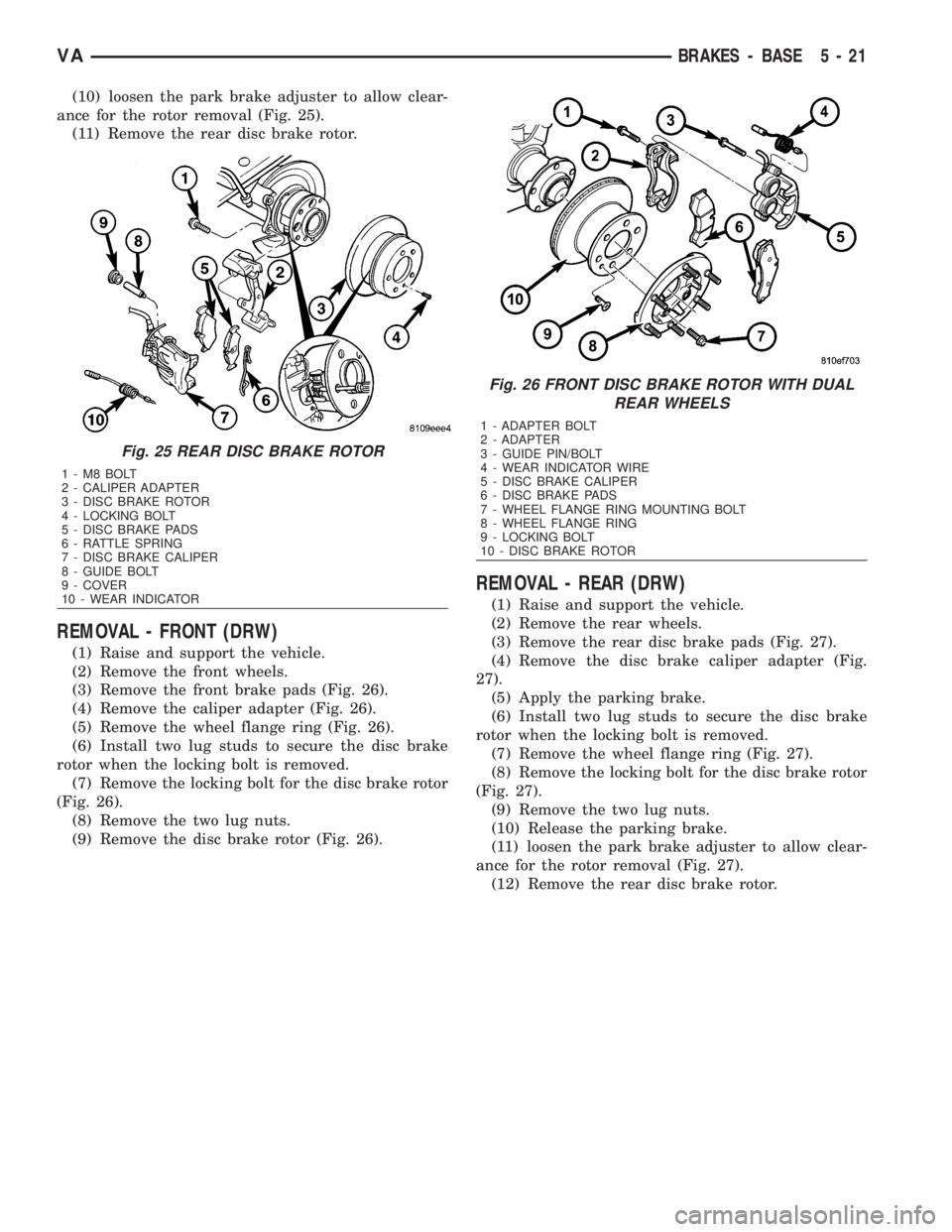
(10) loosen the park brake adjuster to allow clear-
ance for the rotor removal (Fig. 25).
(11) Remove the rear disc brake rotor.
REMOVAL - FRONT (DRW)
(1) Raise and support the vehicle.
(2) Remove the front wheels.
(3) Remove the front brake pads (Fig. 26).
(4) Remove the caliper adapter (Fig. 26).
(5) Remove the wheel flange ring (Fig. 26).
(6) Install two lug studs to secure the disc brake
rotor when the locking bolt is removed.
(7) Remove the locking bolt for the disc brake rotor
(Fig. 26).
(8) Remove the two lug nuts.
(9) Remove the disc brake rotor (Fig. 26).
REMOVAL - REAR (DRW)
(1) Raise and support the vehicle.
(2) Remove the rear wheels.
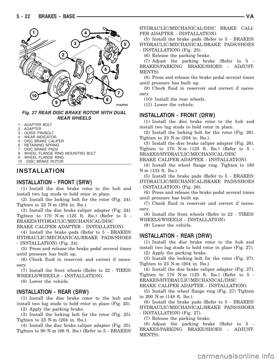
(3) Remove the rear disc brake pads (Fig. 27).
(4) Remove the disc brake caliper adapter (Fig.
27).
(5) Apply the parking brake.
(6) Install two lug studs to secure the disc brake
rotor when the locking bolt is removed.
(7) Remove the wheel flange ring (Fig. 27).
(8) Remove the locking bolt for the disc brake rotor
(Fig. 27).
(9) Remove the two lug nuts.
(10) Release the parking brake.
(11) loosen the park brake adjuster to allow clear-
ance for the rotor removal (Fig. 27).
(12) Remove the rear disc brake rotor.
Fig. 25 REAR DISC BRAKE ROTOR
1-M8BOLT
2 - CALIPER ADAPTER
3 - DISC BRAKE ROTOR
4 - LOCKING BOLT
5 - DISC BRAKE PADS
6 - RATTLE SPRING
7 - DISC BRAKE CALIPER
8 - GUIDE BOLT
9 - COVER
10 - WEAR INDICATOR
Fig. 26 FRONT DISC BRAKE ROTOR WITH DUAL
REAR WHEELS
1 - ADAPTER BOLT
2 - ADAPTER
3 - GUIDE PIN/BOLT
4 - WEAR INDICATOR WIRE
5 - DISC BRAKE CALIPER
6 - DISC BRAKE PADS
7 - WHEEL FLANGE RING MOUNTING BOLT
8 - WHEEL FLANGE RING
9 - LOCKING BOLT
10 - DISC BRAKE ROTOR
VABRAKES - BASE 5 - 21
Page 811 of 2305
INSTALLATION
INSTALLATION - FRONT (SRW)
(1) Install the disc brake rotor to the hub and
install two lug studs to hold rotor in place.
(2) Install the locking bolt for the rotor (Fig. 24).
Tighten to 23 N´m (204 in. lbs.).
(3) Install the disc brake caliper adapter (Fig. 24).
Tighten to 170 N´m (125 ft. lbs.) (Refer to 5 -
BRAKES/HYDRAULIC/MECHANICAL/DISC
BRAKE CALIPER ADAPTER - INSTALLATION).
(4) Install the brake pads (Refer to 5 - BRAKES/
HYDRAULIC/MECHANICAL/BRAKE PADS/SHOES
- INSTALLATION) (Fig. 24).
(5) Press and release the brake pedal several times
until pressure has built up.
(6) Check fluid in reservoir and correct if neces-
sary.
(7) Install the front wheels (Refer to 22 - TIRES/
WHEELS/WHEELS - INSTALLATION).
(8) Lower the vehicle.
INSTALLATION - REAR (SRW)
(1) Install the disc brake rotor to the hub and
install two lug studs to hold rotor in place (Fig. 25).
(2) Apply the parking brake.
(3) Install the locking bolt for the rotor (Fig. 25).
Tighten to 23 N´m (204 in. lbs.).
(4) Install the disc brake caliper adapter (Fig. 25).
Tighten to 90 N´m (66 ft. lbs.) (Refer to 5 - BRAKES/HYDRAULIC/MECHANICAL/DISC BRAKE CALI-
PER ADAPTER - INSTALLATION).
(5) Install the brake pads (Refer to 5 - BRAKES/
HYDRAULIC/MECHANICAL/BRAKE PADS/SHOES
- INSTALLATION) (Fig. 25).
(6) Release the parking brake.
(7) Adjust the parking brake (Refer to 5 -
BRAKES/PARKING BRAKE/SHOES - ADJUST-
MENTS).
(8) Press and release the brake pedal several times
until pressure has built up.
(9) Check fluid in reservoir and correct if neces-
sary.
(10) Install the rear wheels.
(11) Lower the vehicle.
INSTALLATION - FRONT (DRW)
(1) Install the disc brake rotor to the hub and
install two lug studs to hold rotor in place.
(2) Install the locking bolt for the rotor (Fig. 26).
Tighten to 23 N´m (204 in. lbs.).
(3) Install the disc brake caliper adapter (Fig. 26).
Tighten to 170 N´m (125 ft. lbs.) (Refer to 5 -
BRAKES/HYDRAULIC/MECHANICAL/DISC
BRAKE CALIPER ADAPTER - INSTALLATION).
(4) Install the wheel flange ring. Tighten to 180
N´m (133 ft. lbs.)
(5) Install the brake pads (Refer to 5 - BRAKES/
HYDRAULIC/MECHANICAL/BRAKE PADS/SHOES
- INSTALLATION) (Fig. 26).
(6) Press and release the brake pedal several times
until pressure has built up.
(7) Check fluid in reservoir and correct if neces-
sary.
(8) Install the front wheels (Refer to 22 - TIRES/
WHEELS/WHEELS - INSTALLATION).
(9) Lower the vehicle.
INSTALLATION - REAR (DRW)
(1) Install the disc brake rotor to the hub and
install two lug studs to hold rotor in place (Fig. 27).
(2) Apply the parking brake.
(3) Install the locking bolt for the rotor (Fig. 27).
Tighten to 23 N´m (204 in. lbs.).
(4) Install the disc brake caliper adapter (Fig. 27).
Tighten to 170 N´m (125 ft. lbs.) (Refer to 5 -
BRAKES/HYDRAULIC/MECHANICAL/DISC
BRAKE CALIPER ADAPTER - INSTALLATION).
(5) Install the wheel flange ring (Fig. 27) Tighten
to 200 N´m (148 ft. lbs.).
(6) Install the brake pads (Refer to 5 - BRAKES/
HYDRAULIC/MECHANICAL/BRAKE PADS/SHOES
- INSTALLATION) (Fig. 27).
(7) Release the parking brake.
(8) Adjust the parking brake (Refer to 5 -
BRAKES/PARKING BRAKE/SHOES - ADJUST-
MENTS).
Fig. 27 REAR DISC BRAKE ROTOR WITH DUAL
REAR WHEELS
1 - ADAPTER BOLT
2 - ADAPTER
3 - GUIDE PIN/BOLT
4 - WEAR INDICATOR
5 - DISC BRAKE CALIPER
6 - RETAINING SPRING
7 - DISC BRAKE PADS
8 - WHEEL FLANGE RING MOUNITNG BOLT
9 - WHEEL FLANGE RING
10 - DISC BRAKE ROTOR
5 - 22 BRAKES - BASEVA
Page 812 of 2305
(9) Press and release the brake pedal several times
until pressure has built up.
(10) Check fluid in reservoir and correct if neces-
sary.
(11) Install the rear wheels.
(12) Lower the vehicle.
SUPPORT PLATE
REMOVAL - REAR
(1) Raise and support the vehicle.
(2) Remove the disc brake caliper adapter (Refer to
5 - BRAKES/HYDRAULIC/MECHANICAL/DISC
BRAKE CALIPER ADAPTER - REMOVAL).
(3) Remove the disc brake rotor (Refer to 5 -
BRAKES/HYDRAULIC/MECHANICAL/ROTORS -
REMOVAL).
(4) Remove the rear park brake shoes (Refer to 5 -
BRAKES/PARKING BRAKE/SHOES - REMOVAL).
(5) Remove the park brake cable from he support
plate.
(6) Remove the rear axle bearing (Refer to 3 - DIF-
FERENTIAL & DRIVELINE/REAR AXLE/AXLE
BEARINGS - REMOVAL).(7) Remove brake support plate.
INSTALLATION - REAR
(1) Press the brake support plate with the axle
bearing onto the axle shaft (Refer to 3 - DIFFEREN-
TIAL & DRIVELINE/REAR AXLE/AXLE BEARINGS
- INSTALLATION).
(2) Install the park brake cable to the support
plate.
(3) Install the rear park brake shoes (Refer to 5 -
BRAKES/PARKING BRAKE/SHOES - INSTALLA-
TION).
(4) Install the disc brake rotor (Refer to 5 -
BRAKES/HYDRAULIC/MECHANICAL/ROTORS -
INSTALLATION).
(5) Install the disc brake caliper adapter (Refer to
5 - BRAKES/HYDRAULIC/MECHANICAL/DISC
BRAKE CALIPER ADAPTER - INSTALLATION).
(6) Adjust the rear park brake shoes (Refer to 5 -
BRAKES/PARKING BRAKE/SHOES - ADJUST-
MENTS).
(7) Install the rear wheels (Refer to 22 - TIRES/
WHEELS/WHEELS - INSTALLATION).
PARKING BRAKE
SPECIFICATIONS
TORQUE CHART
TORQUE SPECIFICATIONS
DESCRIPTION N´m Ft. Lbs. In. Lbs.
Pressure Transformer Unit
For Brake Cables To
Frame Crossmember25 Ð 221
Hand Brake Lever To
Seat Frame25 Ð 221
VABRAKES - BASE 5 - 23
Page 815 of 2305
INSTALLATION - REAR
NOTE: Route the park brake cable free of tension
and the risk of chafing.
(1) Install the hand brake cable to the anchor
plate (Fig. 31).
(2) Install the park brake cable lock (Fig. 31).
(3) Install all connections on the hardware cable
(Fig. 31).
(4) Install the park brake cables to the shoe (Fig.
31).
(5) Install the park brake shoes.
(6) Install the rear wheels.
(7) Adjust the park brakes.
(8) Lower the vehicle.
ADJUSTMENTS
ADJUSTMENT - PARKING BRAKE CABLES
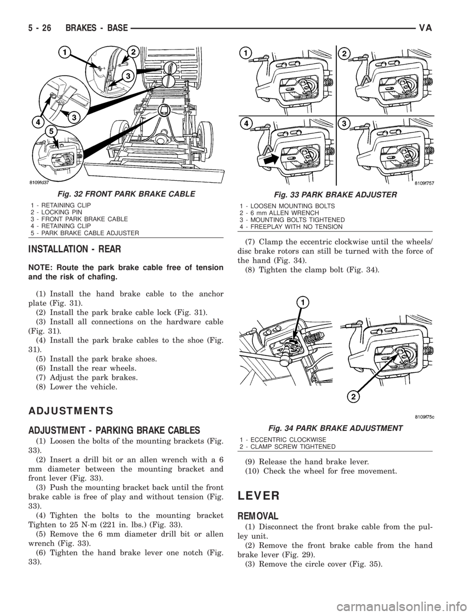
(1) Loosen the bolts of the mounting brackets (Fig.
33).
(2) Insert a drill bit or an allen wrench with a 6
mm diameter between the mounting bracket and
front lever (Fig. 33).
(3) Push the mounting bracket back until the front
brake cable is free of play and without tension (Fig.
33).
(4) Tighten the bolts to the mounting bracket
Tighten to 25 N´m (221 in. lbs.) (Fig. 33).
(5) Remove the 6 mm diameter drill bit or allen
wrench (Fig. 33).
(6) Tighten the hand brake lever one notch (Fig.
33).(7) Clamp the eccentric clockwise until the wheels/
disc brake rotors can still be turned with the force of
the hand (Fig. 34).
(8) Tighten the clamp bolt (Fig. 34).
(9) Release the hand brake lever.
(10) Check the wheel for free movement.
LEVER
REMOVAL
(1) Disconnect the front brake cable from the pul-
ley unit.
(2) Remove the front brake cable from the hand
brake lever (Fig. 29).
(3) Remove the circle cover (Fig. 35).
Fig. 32 FRONT PARK BRAKE CABLE
1 - RETAINING CLIP
2 - LOCKING PIN
3 - FRONT PARK BRAKE CABLE
4 - RETAINING CLIP
5 - PARK BRAKE CABLE ADJUSTER
Fig. 33 PARK BRAKE ADJUSTER
1 - LOOSEN MOUNTING BOLTS
2-6mmALLEN WRENCH
3 - MOUNTING BOLTS TIGHTENED
4 - FREEPLAY WITH NO TENSION
Fig. 34 PARK BRAKE ADJUSTMENT
1 - ECCENTRIC CLOCKWISE
2 - CLAMP SCREW TIGHTENED
5 - 26 BRAKES - BASEVA