2006 MERCEDES-BENZ SPRINTER ECO mode
[x] Cancel search: ECO modePage 316 of 2305
DIAGNOSTIC TEST PROCEDURES — TELL US!
DaimlerChrysler Corporation is constantly working to provide the technician the best diagnostic manuals possible.
Your comments and recommendations regarding the diagnostic manuals and procedures are appreciated.
To best understand your suggestion, please complete the form giving us as much detail as possible.
ModelYearBody TypeEngine
TransmissionVehicle MileageMDH
Diagnostic ProcedureBook No.Page
Comments/recommendations (if necessary, draw sketch)
Name
Submitted by:
Address
City/State/Zip
Business Phone #
All comments become property of DaimlerChrysler Corporation and may be used without compensation.
Page 323 of 2305

enable the HCU to perform the brake fluid manage-
ment control as the combination/proportioning
valves.
The Bosch 5.7 system uses the CAB/HCU/Pump
Motor to make an integral electronic/hydraulic unit
which shares data with other electronic modules on
the vehicle via the CAN C Bus network. To access
DTCs from the CAB, the DRBIIItuses the K-ABS
line located in the Data Link Connector (DLC).
3.3 BRAKE ASSIST SYSTEM (HBA)
The Brake Assist System (HBA) analyzes how
hard and fast the driver wants to brake. It monitors
the brake pressure via a pressure sensor. The
passenger car brake assist system uses a vacuum
booster solenoid. The Sprinter uses the hydraulic
control unit to develop the brake pressure.
3.4 TCS (ASR)
The primary function of the Traction Control System
is to reduce wheel slip and maintain traction at the
driven wheels when the road surfaces are slippery. The
Traction Control System reduces wheel slip by applying
the brake that has lost traction. The system is designed
to operate at speeds below 50 km/h (30 mph). The
engine's torque can be reduced by the ECM via the CAN
C Bus, if necessary. The TCS can be deactivated with
switch on the dash. The Traction Control System uses
the ABS to indicate spinning tires to enable the traction
control function. The TCS software is in the CAB.
The TCS (ASR) performs the following functions:
1. Engine power derate
2. Engine deceleration regulation. If the vehicle is
on a patch of ice, the simple action of releasing
the throttle is enough to cause the rear wheels to
slip. To avoid this, the throttle input is regulated
so power drops slowly instead of abruptly. The
engine power is reduced (decelerated) as neces-
sary.
3.5 ELECTRONIC BRAKE DISTRIBUTION
(EBD)
The system was enhanced and eliminates the
need for the ALB system (load sensing valve). All
ESP equipped models will not have ALB. The EBV
system self-adapts to operating conditions. It de-
tects the vehicle's payload when the vehicle starts
and pulls away. Based on the acceleration rate
when the vehicle first pulls away from a standstill,
the system is able to calculate the actual payload.
This is a rough estimate which is used initially.
Later on, the system gathers more precise informa-
tion by monitoring the brake pressure and wheel
speed and negative slip when the driver applies thebrakes. The system will then produce a more accu-
rate calculation of payload depending on brake
retardation. The adaptation is erased when the
ignition is switched off. A new adaptation will occur
on the next driving cycle. By default, the system
acts upon the vehicle as if in an unloaded condition
(safe mode).
Once a new driving cycle begins with the vehicle
in a fully loaded condition (without having gathered
more precise information) the system will detect
ABS actuation in the front wheels and will allow
enough pressure to be applied to the rear axle, to an
extent where the wheels are just about to lock up
(maximum braking possible).
The system calculates the braking force at the
front and rear axles. If the driver applies the brakes
gently and then realizes he needs to apply the
brakes further, the EBV allows the proper pressure
to be applied to the front and rear brakes.
The EBV also contains a feature called ªcorner
brake systemº (CBS) which operates when the ve-
hicle is braked while cornering to avoid a possible
oversteering condition. The EBV monitors the
wheel speed of both rear wheels to detect when the
vehicle is cornering and allows precise brake pres-
sure application to the front and rear brakes. Also
when the brakes are applied during cornering, the
outer wheels get more of the vehicle's weight while
the inner wheels get less weight and could lose
traction (wheel lock up). The EBV system splits the
pressure between left and right sides in addition to
front and rear brakes.
3.6 VEHICLE CONTROLLING (FZR)
Vehicle controlling (FZR)requires additional
sensors to operate. The term ESP refers to the
software of the system. The term FZR refers to the
system controller. The TCS (ASR) system requires
wheel speed sensors to monitor wheel slip and CAN
bus communications to regulate engine power. In
addition to these inputs, the vehicle controlling
(FZR) requires a steering angle sensor, and a lateral
acceleration/yaw rate sensor.
The ESP system does not take the vehicle load
into account. Instead, the coefficient of friction is
calculated in a 20 millisecond period, where the
controller measures the rate at which the wheel
speed is decelerated, as brake pressure is applied to
the wheel.
3.7 SYSTEM COMPONENTS
²Controller Antilock Brake (CAB)
²Hydraulic Control Unit (HCU)
²Pump Motor
2
GENERAL INFORMATION
Page 410 of 2305
DIAGNOSTIC TEST PROCEDURES — TELL US!
DaimlerChrysler Corporation is constantly working to provide the technician the best diagnostic manuals possible.
Your comments and recommendations regarding the diagnostic manuals and procedures are appreciated.
To best understand your suggestion, please complete the form giving us as much detail as possible.
ModelYearBody TypeEngine
TransmissionVehicle MileageMDH
Diagnostic ProcedureBook No.Page
Comments/recommendations (if necessary, draw sketch)
Name
Submitted by:
Address
City/State/Zip
Business Phone #
All comments become property of DaimlerChrysler Corporation and may be used without compensation.
Page 512 of 2305
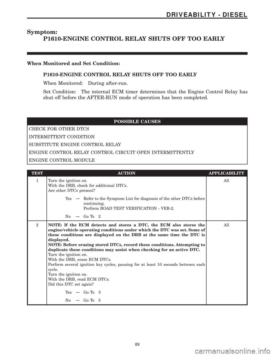
Symptom:
P1610-ENGINE CONTROL RELAY SHUTS OFF TOO EARLY
When Monitored and Set Condition:
P1610-ENGINE CONTROL RELAY SHUTS OFF TOO EARLY
When Monitored: During after-run.
Set Condition: The internal ECM timer determines that the Engine Control Relay has
shut off before the AFTER-RUN mode of operation has been completed.
POSSIBLE CAUSES
CHECK FOR OTHER DTCS
INTERMITTENT CONDITION
SUBSTITUTE ENGINE CONTROL RELAY
ENGINE CONTROL RELAY CONTROL CIRCUIT OPEN INTERMITTENTLY
ENGINE CONTROL MODULE
TEST ACTION APPLICABILITY
1 Turn the ignition on.
With the DRB, check for additional DTCs.
Are other DTCs present?All
Ye s!Refer to the Symptom List for diagnosis of the other DTCs before
continuing.
Perform ROAD TEST VERIFICATION - VER-2.
No!Go To 2
2NOTE: If the ECM detects and stores a DTC, the ECM also stores the
engine/vehicle operating conditions under which the DTC was set. Some of
these conditions are displayed on the DRB at the same time the DTC is
displayed.
NOTE: Before erasing stored DTCs, record these conditions. Attempting to
duplicate these conditions may assist when checking for an active DTC.
Turn the ignition on.
With the DRB, erase ECM DTCs.
Perform several ignition key cycles, pausing for at least 10 seconds between each
cycle.
Turn the ignition on.
With the DRB, read ECM DTCs.
Did this DTC set again?All
Ye s!Go To 3
No!Go To 5
89
DRIVEABILITY - DIESEL
Page 702 of 2305
DIAGNOSTIC TEST PROCEDURES — TELL US!
DaimlerChrysler Corporation is constantly working to provide the technician the best diagnostic manuals possible.
Your comments and recommendations regarding the diagnostic manuals and procedures are appreciated.
To best understand your suggestion, please complete the form giving us as much detail as possible.
ModelYearBody TypeEngine
TransmissionVehicle MileageMDH
Diagnostic ProcedureBook No.Page
Comments/recommendations (if necessary, draw sketch)
Name
Submitted by:
Address
City/State/Zip
Business Phone #
All comments become property of DaimlerChrysler Corporation and may be used without compensation.
Page 706 of 2305
INTRODUCTION
TABLE OF CONTENTS
page page
VEHICLE IDENTIFICATION NUMBER
DESCRIPTION..........................1
INTERNATIONAL SYMBOLS
DESCRIPTION..........................2
FASTENER IDENTIFICATION
DESCRIPTION..........................3
FASTENER USAGE
DESCRIPTION - FASTENER USAGE.........6THREADED HOLE REPAIR
DESCRIPTION - THREADED HOLE REPAIR....6
METRIC SYSTEM
DESCRIPTION..........................6
TORQUE REFERENCES
DESCRIPTION..........................9
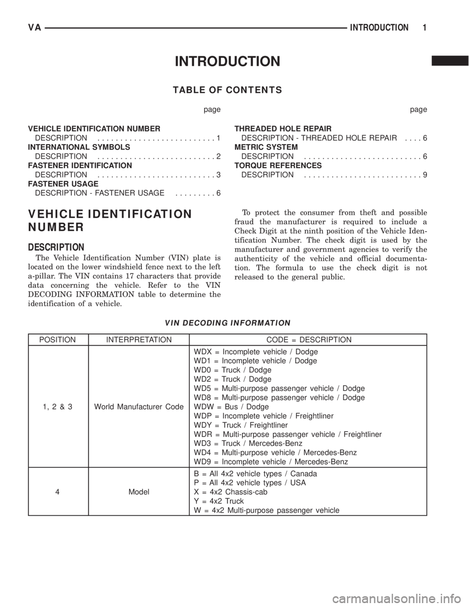
VEHICLE IDENTIFICATION
NUMBER
DESCRIPTION
The Vehicle Identification Number (VIN) plate is
located on the lower windshield fence next to the left
a-pillar. The VIN contains 17 characters that provide
data concerning the vehicle. Refer to the VIN
DECODING INFORMATION table to determine the
identification of a vehicle.To protect the consumer from theft and possible
fraud the manufacturer is required to include a
Check Digit at the ninth position of the Vehicle Iden-
tification Number. The check digit is used by the
manufacturer and government agencies to verify the
authenticity of the vehicle and official documenta-
tion. The formula to use the check digit is not
released to the general public.
VIN DECODING INFORMATION
POSITION INTERPRETATION CODE = DESCRIPTION
1,2&3 World Manufacturer CodeWDX = Incomplete vehicle / Dodge
WD1 = Incomplete vehicle / Dodge
WD0 = Truck / Dodge
WD2 = Truck / Dodge
WD5 = Multi-purpose passenger vehicle / Dodge
WD8 = Multi-purpose passenger vehicle / Dodge
WDW = Bus / Dodge
WDP = Incomplete vehicle / Freightliner
WDY = Truck / Freightliner
WDR = Multi-purpose passenger vehicle / Freightliner
WD3 = Truck / Mercedes-Benz
WD4 = Multi-purpose vehicle / Mercedes-Benz
WD9 = Incomplete vehicle / Mercedes-Benz
4 ModelB = All 4x2 vehicle types / Canada
P = All 4x2 vehicle types / USA
X = 4x2 Chassis-cab
Y = 4x2 Truck
W = 4x2 Multi-purpose passenger vehicle
VAINTRODUCTION 1
Page 808 of 2305
INSTALLATION
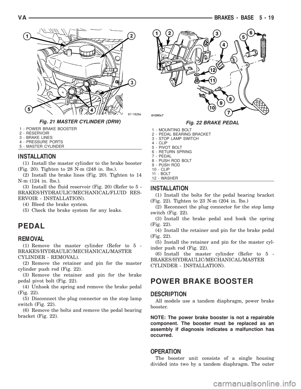
(1) Install the master cylinder to the brake booster
(Fig. 20). Tighten to 28 N´m (248 in. lbs.).
(2) Install the brake lines (Fig. 20). Tighten to 14
N´m (124 in. lbs.).
(3) Install the fluid reservoir (Fig. 20) (Refer to 5 -
BRAKES/HYDRAULIC/MECHANICAL/FLUID RES-
ERVOIR - INSTALLATION).
(4) Bleed the brake system.
(5) Check the brake system for any leaks.
PEDAL
REMOVAL
(1) Remove the master cylinder (Refer to 5 -
BRAKES/HYDRAULIC/MECHANICAL/MASTER
CYLINDER - REMOVAL).
(2) Remove the retainer and pin for the master
cylinder push rod (Fig. 22).
(3) Remove the retainer and pin for the brake
pedal pivot bolt (Fig. 22).
(4) Unhook the spring and remove the brake pedal
(Fig. 22).
(5) Disconnect the plug connector on the stop lamp
switch (Fig. 22).
(6) Remove the bolts and remove the pedal bearing
bracket (Fig. 22).
INSTALLATION
(1) Install the bolts for the pedal bearing bracket
(Fig. 22). Tighten to 23 N´m (204 in. lbs.)
(2) Reconnect the plug connector for the stop lamp
switch (Fig. 22).
(3) Install the brake pedal and hook the spring
(Fig. 22).
(4) Install the retainer and pin for the brake pedal
(Fig. 22).
(5) Install the retainer and pin for the master cyl-
inder push rod (Fig. 22).
(6) Install the master cylinder (Refer to 5 -
BRAKES/HYDRAULIC/MECHANICAL/MASTER
CYLINDER - INSTALLATION).
POWER BRAKE BOOSTER
DESCRIPTION
All models use a tandem diaphragm, power brake
booster.
NOTE: The power brake booster is not a repairable
component. The booster must be replaced as an
assembly if diagnosis indicates a malfunction has
occurred.
OPERATION
The booster unit consists of a single housing
divided into two by a tandem diaphragm. The outer
Fig. 21 MASTER CYLINDER (DRW)
1 - POWER BRAKE BOOSTER
2 - RESERVOIR
3 - BRAKE LINES
4 - PRESSURE PORTS
5 - MASTER CYLINDER
Fig. 22 BRAKE PEDAL
1 - MOUNTING BOLT
2 - PEDAL BEARING BRACKET
3 - STOP LAMP SWITCH
4 - CLIP
5 - PIVOT BOLT
6 - RETURN SPRING
7 - PEDAL
8 - PUSH ROD BOLT
9 - PUSH ROD
10 - CLIP
11 - BOLT
12 - WASHER
VABRAKES - BASE 5 - 19
Page 828 of 2305
COOLING
TABLE OF CONTENTS
page page
COOLING
OPERATION - COOLING SYSTEM...........1
DIAGNOSIS AND TESTING
DIAGNOSIS AND TESTING - PRELIMINARY
CHECKS.............................1COOLING SYSTEM.....................2
ACCESSORY DRIVE.......................5
ENGINE.................................9
COOLING
OPERATION - COOLING SYSTEM
The cooling system regulates engine operating tem-
perature. It allows the engine to reach normal oper-
ating temperature as quickly as possible. It also
maintains normal operating temperature and pre-
vents overheating.
The cooling system also provides a means of heat-
ing the passenger compartment and cooling the auto-
matic transmission fluid (if equipped). The cooling
system is pressurized and uses a centrifugal water
pump to circulate coolant throughout the system.
DIAGNOSIS AND TESTING
DIAGNOSIS AND TESTING - PRELIMINARY
CHECKS
ENGINE COOLING SYSTEM OVERHEATING
Establish what driving conditions caused the com-
plaint. Abnormal loads on the cooling system such as
the following may be the cause:
²PROLONGED IDLE
²VERY HIGH AMBIENT TEMPERATURE
²SLIGHT TAIL WIND AT IDLE
²SLOW TRAFFIC
²TRAFFIC JAMS
²HIGH SPEED OR STEEP GRADES
Driving techniques that avoid overheating are:
²Idle with A/C off when temperature gauge is at
end of normal range.²Increasing engine speed for more air flow is rec-
ommended.
TRAILER TOWING:
Consult Trailer Towing section of owners manual.
Do not exceed limits.
AIR CONDITIONING; ADD - ON OR AFTER MARKET:
A maximum cooling package should have been
ordered with vehicle if add-on or after market A/C is
installed. If not, maximum cooling system compo-
nents should be installed for model involved per
manufacturer's specifications.
RECENT SERVICE OR ACCIDENT REPAIR:
Determine if any recent service has been per-
formed on vehicle that may effect cooling system.
This may be:
²Engine adjustments (incorrect timing)
²Slipping engine accessory drive belt(s)
²Brakes (possibly dragging)
²Changed parts. Incorrect water pump or pump
rotating in wrong direction due to belt not correctly
routed
²Reconditioned radiator or cooling system refill-
ing (possibly under filled or air trapped in system).
NOTE: If investigation reveals none of the previous
items as a cause for an engine overheating com-
plaint, (Refer to 7 - COOLING - DIAGNOSIS AND
TESTING)
VACOOLING 7 - 1