2006 MERCEDES-BENZ SPRINTER power steering fluid
[x] Cancel search: power steering fluidPage 323 of 2305

enable the HCU to perform the brake fluid manage-
ment control as the combination/proportioning
valves.
The Bosch 5.7 system uses the CAB/HCU/Pump
Motor to make an integral electronic/hydraulic unit
which shares data with other electronic modules on
the vehicle via the CAN C Bus network. To access
DTCs from the CAB, the DRBIIItuses the K-ABS
line located in the Data Link Connector (DLC).
3.3 BRAKE ASSIST SYSTEM (HBA)
The Brake Assist System (HBA) analyzes how
hard and fast the driver wants to brake. It monitors
the brake pressure via a pressure sensor. The
passenger car brake assist system uses a vacuum
booster solenoid. The Sprinter uses the hydraulic
control unit to develop the brake pressure.
3.4 TCS (ASR)
The primary function of the Traction Control System
is to reduce wheel slip and maintain traction at the
driven wheels when the road surfaces are slippery. The
Traction Control System reduces wheel slip by applying
the brake that has lost traction. The system is designed
to operate at speeds below 50 km/h (30 mph). The
engine's torque can be reduced by the ECM via the CAN
C Bus, if necessary. The TCS can be deactivated with
switch on the dash. The Traction Control System uses
the ABS to indicate spinning tires to enable the traction
control function. The TCS software is in the CAB.
The TCS (ASR) performs the following functions:
1. Engine power derate
2. Engine deceleration regulation. If the vehicle is
on a patch of ice, the simple action of releasing
the throttle is enough to cause the rear wheels to
slip. To avoid this, the throttle input is regulated
so power drops slowly instead of abruptly. The
engine power is reduced (decelerated) as neces-
sary.
3.5 ELECTRONIC BRAKE DISTRIBUTION
(EBD)
The system was enhanced and eliminates the
need for the ALB system (load sensing valve). All
ESP equipped models will not have ALB. The EBV
system self-adapts to operating conditions. It de-
tects the vehicle's payload when the vehicle starts
and pulls away. Based on the acceleration rate
when the vehicle first pulls away from a standstill,
the system is able to calculate the actual payload.
This is a rough estimate which is used initially.
Later on, the system gathers more precise informa-
tion by monitoring the brake pressure and wheel
speed and negative slip when the driver applies thebrakes. The system will then produce a more accu-
rate calculation of payload depending on brake
retardation. The adaptation is erased when the
ignition is switched off. A new adaptation will occur
on the next driving cycle. By default, the system
acts upon the vehicle as if in an unloaded condition
(safe mode).
Once a new driving cycle begins with the vehicle
in a fully loaded condition (without having gathered
more precise information) the system will detect
ABS actuation in the front wheels and will allow
enough pressure to be applied to the rear axle, to an
extent where the wheels are just about to lock up
(maximum braking possible).
The system calculates the braking force at the
front and rear axles. If the driver applies the brakes
gently and then realizes he needs to apply the
brakes further, the EBV allows the proper pressure
to be applied to the front and rear brakes.
The EBV also contains a feature called ªcorner
brake systemº (CBS) which operates when the ve-
hicle is braked while cornering to avoid a possible
oversteering condition. The EBV monitors the
wheel speed of both rear wheels to detect when the
vehicle is cornering and allows precise brake pres-
sure application to the front and rear brakes. Also
when the brakes are applied during cornering, the
outer wheels get more of the vehicle's weight while
the inner wheels get less weight and could lose
traction (wheel lock up). The EBV system splits the
pressure between left and right sides in addition to
front and rear brakes.
3.6 VEHICLE CONTROLLING (FZR)
Vehicle controlling (FZR)requires additional
sensors to operate. The term ESP refers to the
software of the system. The term FZR refers to the
system controller. The TCS (ASR) system requires
wheel speed sensors to monitor wheel slip and CAN
bus communications to regulate engine power. In
addition to these inputs, the vehicle controlling
(FZR) requires a steering angle sensor, and a lateral
acceleration/yaw rate sensor.
The ESP system does not take the vehicle load
into account. Instead, the coefficient of friction is
calculated in a 20 millisecond period, where the
controller measures the rate at which the wheel
speed is decelerated, as brake pressure is applied to
the wheel.
3.7 SYSTEM COMPONENTS
²Controller Antilock Brake (CAB)
²Hydraulic Control Unit (HCU)
²Pump Motor
2
GENERAL INFORMATION
Page 716 of 2305
LUBRICATION & MAINTENANCE
TABLE OF CONTENTS
page page
FLUID TYPES
DESCRIPTION
PARTS AND LUBRICANT
RECOMMENDATIONS...................1
AUTOMATIC TRANSMISSION FLUID - NAG1 . 1
AXLE FLUID..........................2
BRAKE FLUID.........................2
HOAT COOLANT.......................2
ENGINE OIL - DIESEL ENGINES...........3
FUEL REQUIREMENTS - DIESEL ENGINE . . . 4
POWER STEERING FLUID...............5
OPERATION - AUTOMATIC TRANSMISSION
FLUID...............................5
FLUID CAPACITIES
SPECIFICATIONS - FLUID CAPACITIES.......5FLUID FILL/CHECK LOCATIONS
INSPECTION - FLUID FILL/CHECK
LOCATIONS..........................5
HOISTING
STANDARD PROCEDURE - HOISTING........5
JUMP STARTING
STANDARD PROCEDURE - JUMP STARTING . . 6
TOWING
STANDARD PROCEDURE - TOWING.........7
MAINTENANCE SCHEDULES
DESCRIPTION..........................8
INTERNATIONAL SYMBOLS
DESCRIPTION..........................9
FLUID TYPES
DESCRIPTION
PARTS AND LUBRICANT RECOMMENDATIONS
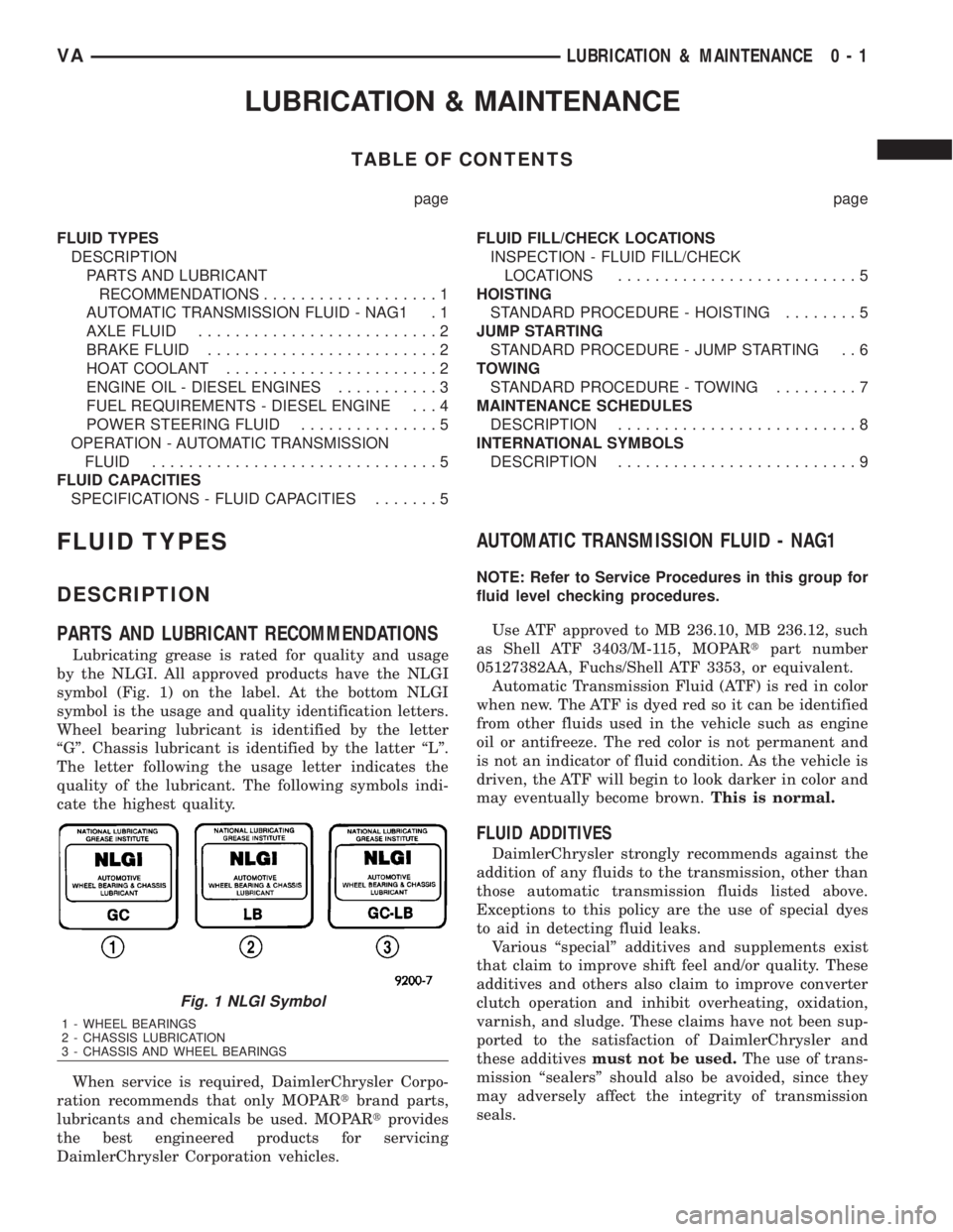
Lubricating grease is rated for quality and usage
by the NLGI. All approved products have the NLGI
symbol (Fig. 1) on the label. At the bottom NLGI
symbol is the usage and quality identification letters.
Wheel bearing lubricant is identified by the letter
ªGº. Chassis lubricant is identified by the latter ªLº.
The letter following the usage letter indicates the
quality of the lubricant. The following symbols indi-
cate the highest quality.
When service is required, DaimlerChrysler Corpo-
ration recommends that only MOPARtbrand parts,
lubricants and chemicals be used. MOPARtprovides
the best engineered products for servicing
DaimlerChrysler Corporation vehicles.
AUTOMATIC TRANSMISSION FLUID - NAG1
NOTE: Refer to Service Procedures in this group for
fluid level checking procedures.
Use ATF approved to MB 236.10, MB 236.12, such
as Shell ATF 3403/M-115, MOPARtpart number
05127382AA, Fuchs/Shell ATF 3353, or equivalent.
Automatic Transmission Fluid (ATF) is red in color
when new. The ATF is dyed red so it can be identified
from other fluids used in the vehicle such as engine
oil or antifreeze. The red color is not permanent and
is not an indicator of fluid condition. As the vehicle is
driven, the ATF will begin to look darker in color and
may eventually become brown.This is normal.
FLUID ADDITIVES
DaimlerChrysler strongly recommends against the
addition of any fluids to the transmission, other than
those automatic transmission fluids listed above.
Exceptions to this policy are the use of special dyes
to aid in detecting fluid leaks.
Various ªspecialº additives and supplements exist
that claim to improve shift feel and/or quality. These
additives and others also claim to improve converter
clutch operation and inhibit overheating, oxidation,
varnish, and sludge. These claims have not been sup-
ported to the satisfaction of DaimlerChrysler and
these additivesmust not be used.The use of trans-
mission ªsealersº should also be avoided, since they
may adversely affect the integrity of transmission
seals.
Fig. 1 NLGI Symbol
1 - WHEEL BEARINGS
2 - CHASSIS LUBRICATION
3 - CHASSIS AND WHEEL BEARINGS
VALUBRICATION & MAINTENANCE 0 - 1
Page 720 of 2305
Do not blend other specific fuel additives with die-
sel fuel. They only result in unnecessary cost, and
may be harmful to the engine operation.
POWER STEERING FLUID
No fluid service required. Filled with Power Steer-
ing Fluid approved to MB 236.3, such as Mobil
ATF-D (Exxon Mobil Corporation) or equivalent.
OPERATION - AUTOMATIC TRANSMISSION
FLUID
The automatic transmission fluid is selected based
upon several qualities. The fluid must provide a high
level of protection for the internal components by
providing a lubricating film between adjacent metal
components. The fluid must also be thermally stable
so that it can maintain a consistent viscosity through
a large temperature range. If the viscosity stays con-
stant through the temperature range of operation,
transmission operation and shift feel will remain con-
sistent. Transmission fluid must also be a good con-
ductor of heat. The fluid must absorb heat from the
internal transmission components and transfer that
heat to the transmission case.
FLUID CAPACITIES
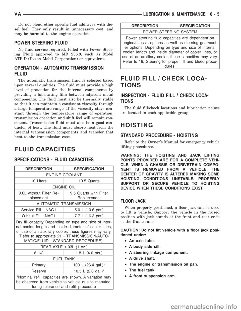
SPECIFICATIONS - FLUID CAPACITIES
DESCRIPTION SPECIFICATION
ENGINE COOLANT
10 Liters 10.5 Quarts
ENGINE OIL
9.0L without Filter Re-
placement9.5 Quarts with Filter
Replacement
AUTOMATIC TRANSMISSION
Service Fill - NAG1 5.0 L (10.6 pts.)
O-haul Fill - NAG1 7.7 L (16.3 pts.)
Dry fill capacity Depending on type and size of inter-
nal cooler, length and inside diameter of cooler lines,
or use of an auxiliary cooler, these figures may vary.
(Refer to appropriate 21 - TRANSMISSION/AUTO-
MATIC/FLUID - STANDARD PROCEDURE).
REAR AXLE .03L (1 oz.)
8 1/2 1.8 L (4.0 pts.)
FUEL TANK
Primary 100 L (26.4 gal.)*
Reserve 10.5 L (2.8 gal.)*
*Nominal refill capacities are shown. A variation may
be observed from vehicle to vehicle due to manufac-
turing tolerance and refill procedure
DESCRIPTION SPECIFICATION
POWER STEERING SYSTEM
Power steering fluid capacities are dependent on
engine/chassis options as well as steering gear/cool-
er options. Depending on type and size of internal
cooler, length and inside diameter of cooler lines, or
use of an auxiliary cooler, these capacities may vary.
Refer to 19, Steering for proper fill and bleed proce-
dures.
FLUID FILL / CHECK LOCA-
TIONS
INSPECTION - FLUID FILL / CHECK LOCA-
TIONS
The fluid fill/check locations and lubrication points
are located in each applicable group.
HOISTING
STANDARD PROCEDURE - HOISTING
Refer to the Owner's Manual for emergency vehicle
lifting procedures.
WARNING: THE HOISTING AND JACK LIFTING
POINTS PROVIDED ARE FOR A COMPLETE VEHI-
CLE. WHEN A CHASSIS OR DRIVETRAIN COMPO-
NENT IS REMOVED FROM A VEHICLE, THE
CENTER OF GRAVITY IS ALTERED MAKING SOME
HOISTING CONDITIONS UNSTABLE. PROPERLY
SUPPORT OR SECURE VEHICLE TO HOISTING
DEVICE WHEN THESE CONDITIONS EXIST.
FLOOR JACK
When properly positioned, a floor jack can be used
to lift a vehicle. Support the vehicle in the raised
position with jack stands at the front and rear ends
of the frame rails.
CAUTION: Do not lift vehicle with a floor jack posi-
tioned under:
²An axle tube.
²A body side sill.
²A steering linkage component.
²A drive shaft.
²The engine or transmission oil pan.
²The fuel tank.
²A front suspension arm.
VALUBRICATION & MAINTENANCE 0 - 5
Page 724 of 2305

SCOPE OF WORK FOR MAINTENANCE SERVICE
Oil Service
²Engine: Oil change and filter replacement
Check fluid levels of the following system, refill as neces-
sary.
²If fluid is lost, trace and eliminate cause - as a
separate order.
²Power-assisted steering
Lubrication work:
²Trailer tow hitch (original equipment)
Maintenance
²ASSYST maintenance computer reset
Function check
²Signalling system, warning and indicator lamps
²Headlamps, exterior lighting
²Windshield wipers, windshield washer system
Check for leaks and damage
²Check for abrasion points and ensure that lines
are correctly routed!
²All lines and hoses, sensor cables
²Rubber boots on front axle drive shafts, rubber
boots on front axle suspension ball joints, shock
absorbers
²Check fluid levels for the following systems, cor-
rect as necessary
NOTE: Should there be a loss of fluid which cannot
be explained by regular use, trace and eliminate the
cause.
²Engine cooling system. Check corrosion inhibi-
tor/antifreeze, refill as necessary.
²Hydraulic brake system
²Battery
²Windshield washer system
Engine
²Fuel filter renewal - Every oil service
²Air cleaner with maintenance indicator:
²Check degree of contamination.
²Air cleaner filter element renewed as necessary.
Chassis and body
²Trailer coupling: Check operation, play and
retaining fixtures
²Secondary rubber springs: Visual check
²Tire pressures: Correct as necessary, including
spare tire
²Check thickness of brake pads
²Brake test
²Check condition of steering mechanism
²Heating/ventilation dust filter renewal
ADDITIONAL MAINTENANCE WORK
Automatic transmission once only at 80,000 miles / 128000
km
²Oil and filter change
During every second maintenance service
²Air cleaner without maintenance indicator:
²Air cleaner filter element renewal
²Check poly-V-belt for wear and signs of damage
During every fourth maintenance service
²Change rear axle fluid
ADDITIONAL MAINTENANCE WORK AFTER YEARS
Every 2 years
²Change brake fluid.
Every 3 years
²Air cleaner filter element renewal (note installa-
tion date)
Every 15 years or 100,000 miles
²Coolant renewal
²Note coolant composition
INTERNATIONAL SYMBOLS
DESCRIPTION
DaimlerChrysler Corporation uses international
symbols to identify engine compartment lubricant
and fluid inspection and fill locations (Fig. 3).
Fig. 3 INTERNATIONAL SYMBOLS
VALUBRICATION & MAINTENANCE 0 - 9
Page 791 of 2305
POWER BRAKE BOOSTER
DESCRIPTION.........................19
OPERATION...........................19
REMOVAL.............................20
INSTALLATION.........................20
ROTORS
REMOVAL
REMOVAL - FRONT (SRW)..............20
REMOVAL - REAR (SRW)...............20
REMOVAL - FRONT (DRW)..............21
REMOVAL - REAR (DRW)...............21
INSTALLATION
INSTALLATION - FRONT (SRW)..........22
INSTALLATION - REAR (SRW)...........22
INSTALLATION - FRONT (DRW)..........22
INSTALLATION - REAR (DRW)...........22
SUPPORT PLATE
REMOVAL - REAR......................23
INSTALLATION - REAR...................23
PARKING BRAKE
SPECIFICATIONS
TORQUE CHART......................23
SPECIAL TOOLS
PARK BRAKE........................24
CABLE TENSIONER
REMOVAL.............................24INSTALLATION.........................24
CABLES
REMOVAL
REMOVAL - FRONT....................24
REMOVAL - REAR.....................25
INSTALLATION
INSTALLATION - FRONT................25
INSTALLATION - REAR.................26
ADJUSTMENTS
ADJUSTMENT - PARKING BRAKE CABLES . 26
LEVER
REMOVAL.............................26
INSTALLATION.........................27
SHOES
REMOVAL
REMOVAL - (SRW)....................27
REMOVAL - (DRW)....................27
CLEANING - REAR DRUM IN HAT BRAKE....28
INSTALLATION
INSTALLATION - (SRW).................28
INSTALLATION - (DRW).................28
ADJUSTMENTS
ADJUSTMENT........................28
BRAKES - BASE
DIAGNOSIS AND TESTING - BASE BRAKE SYS-
TEM
Base brake components consist of the brake pads,
calipers, brake drum in hat rotor in the rear, rotors,
brake lines, master cylinder, booster, and parking
brake components.
Brake diagnosis involves determining if the prob-
lem is related to a mechanical, hydraulic, or vacuum
operated component.
The first diagnosis step is the preliminary check.
PRELIMINARY BRAKE CHECK
(1) Check condition of tires and wheels. Damaged
wheels and worn, damaged, or underinflated tires
can cause pull, shudder, vibration, and a condition
similar to grab.
(2) If complaint was based on noise when braking,
check suspension components. Jounce front and rear
of vehicle and listen for noise that might be caused
by loose, worn or damaged suspension or steering
components.
(3) Inspect brake fluid level and condition. Note
that the brake reservoir fluid level will decrease in
proportion to normal lining wear.Also note that
brake fluid tends to darken over time. This is
normal and should not be mistaken for contam-
ination.(a) If fluid level is abnormally low, look for evi-
dence of leaks at calipers, wheel cylinders, brake
lines, and master cylinder.
(b) If fluid appears contaminated, drain out a
sample to examine. System will have to be flushed
if fluid is separated into layers, or contains a sub-
stance other than brake fluid. The system seals
and cups will also have to be replaced after flush-
ing. Use clean brake fluid to flush the system.
(4) Check parking brake operation. Verify free
movement and full release of cables and pedal. Also
note if vehicle was being operated with parking
brake partially applied.
(5) Check brake pedal operation. Verify that pedal
does not bind and has adequate free play. If pedal
lacks free play, check pedal and power booster for
being loose or for bind condition. Do not road test
until condition is corrected.
(6) Check booster vacuum check valve and hose.
(7) If components checked appear OK, road test
the vehicle.
ROAD TESTING
(1) If complaint involved low brake pedal, pump
pedal and note if it comes back up to normal height.
(2) Check brake pedal response with transmission
in Neutral and engine running. Pedal should remain
firm under constant foot pressure.
5 - 2 BRAKES - BASEVA
Page 804 of 2305
FLUID
DIAGNOSIS AND TESTING - BRAKE FLUID
CONTAMINATION
Indications of fluid contamination are swollen or
deteriorated rubber parts.
Swollen rubber parts indicate the presence of
petroleum in the brake fluid.
To test for contamination, put a small amount of
drained brake fluid in clear glass jar. If fluid sepa-
rates into layers, there is mineral oil or other fluid
contamination of the brake fluid.
If brake fluid is contaminated, drain and thor-
oughly flush system. Replace master cylinder, ALB
Controller, caliper seals, Antilock Brakes hydraulic
unit and all hydraulic fluid hoses.
STANDARD PROCEDURE - BRAKE FLUID
LEVEL
Always clean the master cylinder reservoir and
caps before checking fluid level. If not cleaned, dirt
could enter the fluid.
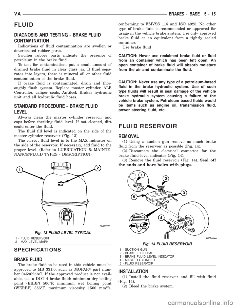
The fluid fill level is indicated on the side of the
master cylinder reservoir (Fig. 13).
The correct fluid level is to the MAX indicator on
the side of the reservoir. If necessary, add fluid to the
proper level. (Refer to LUBRICATION & MAINTE-
NANCE/FLUID TYPES - DESCRIPTION).
SPECIFICATIONS
BRAKE FLUID
The brake fluid to be used in this vehicle must be
approved to MB 331.0, such as MOPARtpart num-
ber 0459625AC. If the approved product is not avail-
able, use a DOT 4 brake fluid: minimum dry boiling
point (ERBP) 500ÉF, minimum wet boiling point
(WERBP) 356ÉF, maximum viscosity 1500 mm
2/s,conforming to FMVSS 116 and ISO 4925. No other
type of brake fluid is recommended or approved for
usage in the vehicle brake system. Use only approved
brake fluid or an equivalent from a tightly sealed
container.
Use brake fluid
CAUTION: Never use reclaimed brake fluid or fluid
from an container which has been left open. An
open container of brake fluid will absorb moisture
from the air and contaminate the fluid.
CAUTION: Never use any type of a petroleum-based
fluid in the brake hydraulic system. Use of such
type fluids will result in seal damage of the vehicle
brake hydraulic system causing a failure of the
vehicle brake system. Petroleum based fluids would
be items such as engine oil, transmission fluid,
power steering fluid, etc.
FLUID RESERVOIR
REMOVAL
(1) Using a suction gun remove as much brake
fluid from the reservoir as possible (Fig. 14).
(2) Disconnect the electrical connector for the
brake fluid level indicator (Fig. 14).
(3) Remove the fluid reservoir (Fig. 14).Seal off
the ends and bore holes with plugs.
INSTALLATION
(1) Install the fluid reservoir and fill with fluid
(Fig. 14).
(2) Bleed the brake system.
Fig. 13 FLUID LEVEL TYPICAL
1 - FLUID RESERVOIR
2 - MAX LEVEL MARK
Fig. 14 FLUID RESERVOIR
1 - SUCTION GUN
2 - BRAKE FLUID CAP
3 - BRAKE FLUID LEVEL INDICATOR
4 - MASTER CYLINDER
5 - FLUID RESERVOIR
VABRAKES - BASE 5 - 15
Page 1168 of 2305
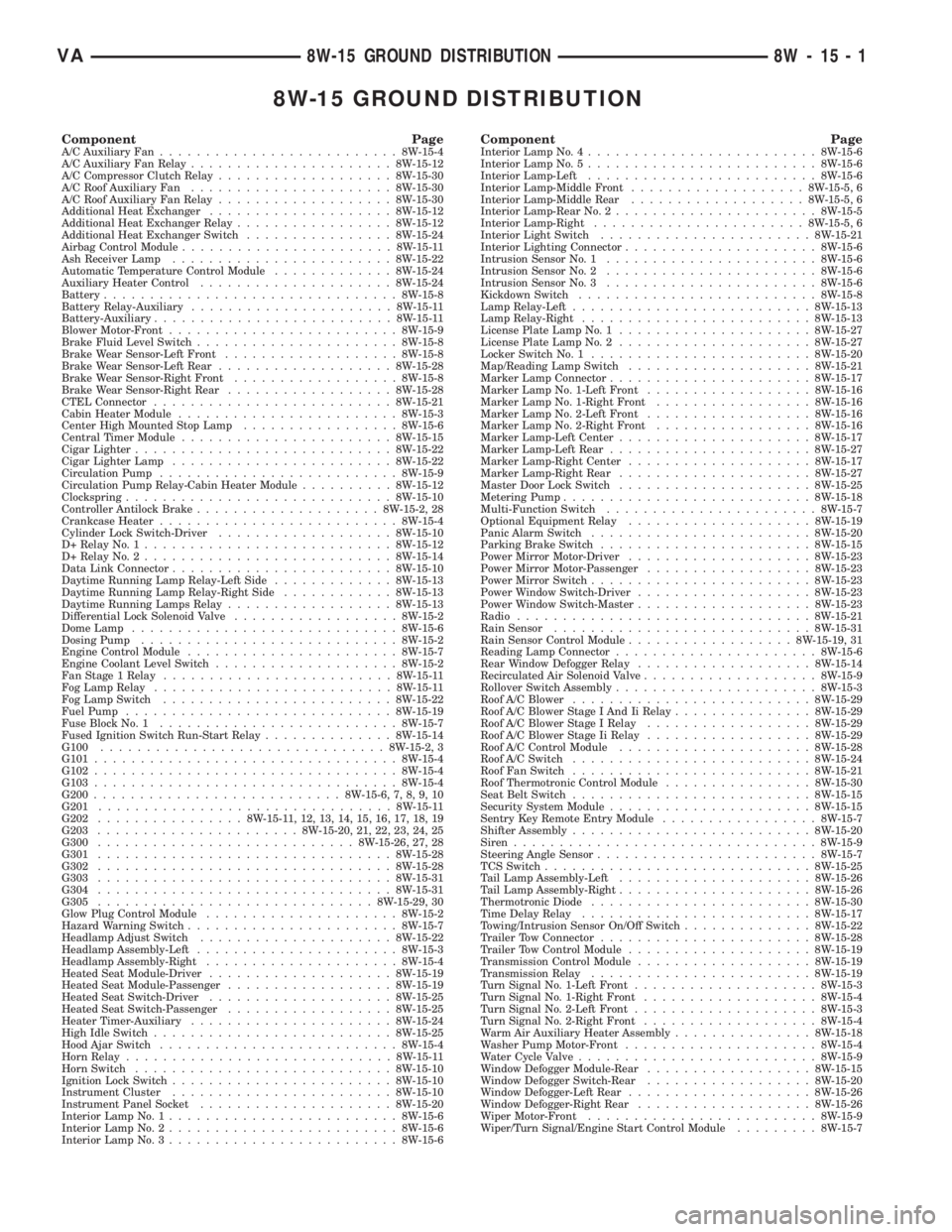
8W-15 GROUND DISTRIBUTION
Component PageA/C Auxiliary Fan..........................8W-15-4
A/C Auxiliary Fan Relay......................8W-15-12
A/C Compressor Clutch Relay...................8W-15-30
A/C Roof Auxiliary Fan......................8W-15-30
A/C Roof Auxiliary Fan Relay...................8W-15-30
Additional Heat Exchanger....................8W-15-12
Additional Heat Exchanger Relay.................8W-15-12
Additional Heat Exchanger Switch................8W-15-24
Airbag Control Module.......................8W-15-11
Ash Receiver Lamp........................8W-15-22
Automatic Temperature Control Module.............8W-15-24
Auxiliary Heater Control.....................8W-15-24
Battery................................8W-15-8
Battery Relay-Auxiliary......................8W-15-11
Battery-Auxiliary..........................8W-15-11
Blower Motor-Front.........................8W-15-9
Brake Fluid Level Switch......................8W-15-8
Brake Wear Sensor-Left Front...................8W-15-8
Brake Wear Sensor-Left Rear...................8W-15-28
Brake Wear Sensor-Right Front..................8W-15-8
Brake Wear Sensor-Right Rear..................8W-15-28
CTEL Connector..........................8W-15-21
Cabin Heater Module........................8W-15-3
Center High Mounted Stop Lamp.................8W-15-6
Central Timer Module.......................8W-15-15
Cigar Lighter............................8W-15-22
Cigar Lighter Lamp........................8W-15-22
Circulation Pump..........................8W-15-9
Circulation Pump Relay-Cabin Heater Module..........8W-15-12
Clockspring.............................8W-15-10
Controller Antilock Brake....................8W-15-2, 28
Crankcase Heater..........................8W-15-4
Cylinder Lock Switch-Driver...................8W-15-10
D+ Relay No. 1...........................8W-15-12
D+ Relay No. 2...........................8W-15-14
Data Link Connector........................8W-15-10
Daytime Running Lamp Relay-Left Side.............8W-15-13
Daytime Running Lamp Relay-Right Side............8W-15-13
Daytime Running Lamps Relay..................8W-15-13
Differential Lock Solenoid Valve..................8W-15-2
Dome Lamp.............................8W-15-6
Dosing Pump............................8W-15-2
Engine Control Module.......................8W-15-7
Engine Coolant Level Switch....................8W-15-2
Fan Stage 1 Relay.........................8W-15-11
Fog Lamp Relay..........................8W-15-11
Fog Lamp Switch.........................8W-15-22
Fuel Pump.............................8W-15-19
Fuse Block No. 1..........................8W-15-7
Fused Ignition Switch Run-Start Relay..............8W-15-14
G100...............................8W-15-2, 3
G101.................................8W-15-4
G102.................................8W-15-4
G103.................................8W-15-4
G200...........................8W-15-6, 7, 8, 9, 10
G201................................8W-15-11
G202................8W-15-11, 12, 13, 14, 15, 16, 17, 18, 19
G203......................8W-15-20, 21, 22, 23, 24, 25
G300............................8W-15-26, 27, 28
G301................................8W-15-28
G302................................8W-15-28
G303................................8W-15-31
G304................................8W-15-31
G305..............................8W-15-29, 30
Glow Plug Control Module.....................8W-15-2
Hazard Warning Switch.......................8W-15-7
Headlamp Adjust Switch.....................8W-15-22
Headlamp Assembly-Left......................8W-15-3
Headlamp Assembly-Right.....................8W-15-4
Heated Seat Module-Driver....................8W-15-19
Heated Seat Module-Passenger..................8W-15-19
Heated Seat Switch-Driver....................8W-15-25
Heated Seat Switch-Passenger..................8W-15-25
Heater Timer-Auxiliary......................8W-15-24
High Idle Switch..........................8W-15-25
Hood Ajar Switch..........................8W-15-4
Horn Relay.............................8W-15-11
Horn Switch............................8W-15-10
Ignition Lock Switch........................8W-15-10
Instrument Cluster........................8W-15-10
Instrument Panel Socket.....................8W-15-20
Interior Lamp No. 1.........................8W-15-6
Interior Lamp No. 2.........................8W-15-6
Interior Lamp No. 3.........................8W-15-6Component PageInterior Lamp No. 4.........................8W-15-6
Interior Lamp No. 5.........................8W-15-6
Interior Lamp-Left.........................8W-15-6
Interior Lamp-Middle Front...................8W-15-5, 6
Interior Lamp-Middle Rear...................8W-15-5, 6
Interior Lamp-Rear No. 2......................8W-15-5
Interior Lamp-Right.......................8W-15-5, 6
Interior Light Switch.......................8W-15-21
Interior Lighting Connector.....................8W-15-6
Intrusion Sensor No. 1.......................8W-15-6
Intrusion Sensor No. 2.......................8W-15-6
Intrusion Sensor No. 3.......................8W-15-6
Kickdown Switch..........................8W-15-8
Lamp Relay-Left..........................8W-15-13
Lamp Relay-Right.........................8W-15-13
License Plate Lamp No. 1.....................8W-15-27
License Plate Lamp No. 2.....................8W-15-27
Locker Switch No. 1........................8W-15-20
Map/Reading Lamp Switch....................8W-15-21
Marker Lamp Connector......................8W-15-17
Marker Lamp No. 1-Left Front..................8W-15-16
Marker Lamp No. 1-Right Front.................8W-15-16
Marker Lamp No. 2-Left Front..................8W-15-16
Marker Lamp No. 2-Right Front.................8W-15-16
Marker Lamp-Left Center.....................8W-15-17
Marker Lamp-Left Rear......................8W-15-27
Marker Lamp-Right Center....................8W-15-17
Marker Lamp-Right Rear.....................8W-15-27
Master Door Lock Switch.....................8W-15-25
Metering Pump...........................8W-15-18
Multi-Function Switch.......................8W-15-7
Optional Equipment Relay....................8W-15-19
Panic Alarm Switch........................8W-15-20
Parking Brake Switch.......................8W-15-15
Power Mirror Motor-Driver....................8W-15-23
Power Mirror Motor-Passenger..................8W-15-23
Power Mirror Switch........................8W-15-23
Power Window Switch-Driver...................8W-15-23
Power Window Switch-Master...................8W-15-23
Radio................................8W-15-21
Rain Sensor............................8W-15-31
Rain Sensor Control Module..................8W-15-19, 31
Reading Lamp Connector......................8W-15-6
Rear Window Defogger Relay...................8W-15-14
Recirculated Air Solenoid Valve...................8W-15-9
Rollover Switch Assembly......................8W-15-3
Roof A/C Blower..........................8W-15-29
Roof A/C Blower Stage I And Ii Relay...............8W-15-29
Roof A/C Blower Stage I Relay..................8W-15-29
Roof A/C Blower Stage Ii Relay..................8W-15-29
Roof A/C Control Module.....................8W-15-28
Roof A/C Switch..........................8W-15-24
Roof Fan Switch..........................8W-15-21
Roof Thermotronic Control Module................8W-15-30
Seat Belt Switch..........................8W-15-15
Security System Module......................8W-15-15
Sentry Key Remote Entry Module.................8W-15-7
Shifter Assembly..........................8W-15-20
Siren.................................8W-15-9
Steering Angle Sensor........................8W-15-7
TCS Switch.............................8W-15-25
Tail Lamp Assembly-Left.....................8W-15-26
Tail Lamp Assembly-Right.....................8W-15-26
Thermotronic Diode........................8W-15-30
Time Delay Relay.........................8W-15-17
Towing/Intrusion Sensor On/Off Switch..............8W-15-22
Trailer Tow Connector.......................8W-15-28
Trailer Tow Control Module....................8W-15-19
Transmission Control Module...................8W-15-19
Transmission Relay........................8W-15-19
Turn Signal No. 1-Left Front....................8W-15-3
Turn Signal No. 1-Right Front...................8W-15-4
Turn Signal No. 2-Left Front....................8W-15-3
Turn Signal No. 2-Right Front...................8W-15-4
Warm Air Auxiliary Heater Assembly...............8W-15-18
Washer Pump Motor-Front.....................8W-15-4
Water Cycle Valve..........................8W-15-9
Window Defogger Module-Rear..................8W-15-15
Window Defogger Switch-Rear..................8W-15-20
Window Defogger-Left Rear....................8W-15-26
Window Defogger-Right Rear...................8W-15-26
Wiper Motor-Front.........................8W-15-9
Wiper/Turn Signal/Engine Start Control Module.........8W-15-7
VA8W-15 GROUND DISTRIBUTION 8W - 15 - 1
Page 1254 of 2305
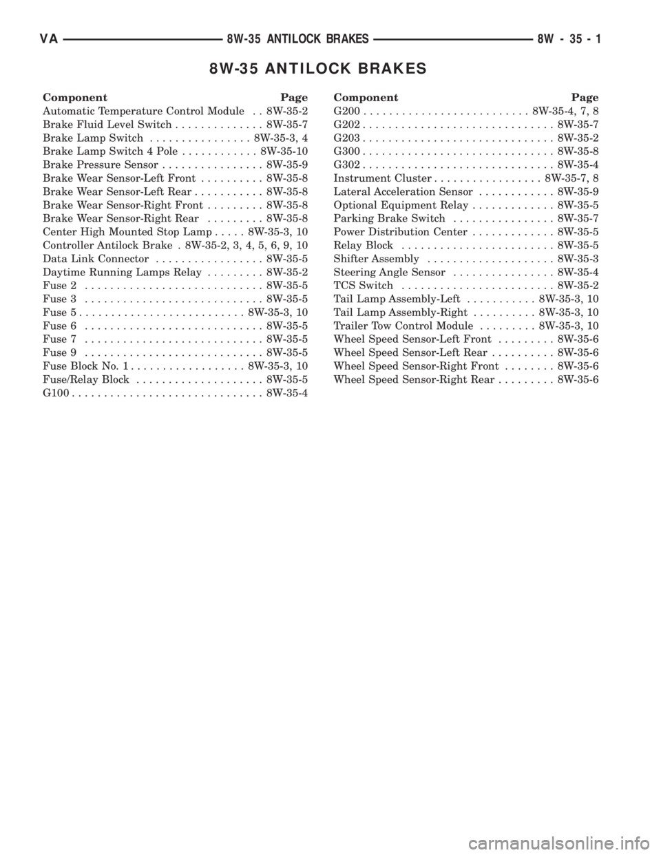
8W-35 ANTILOCK BRAKES
Component Page
Automatic Temperature Control Module . . 8W-35-2
Brake Fluid Level Switch.............. 8W-35-7
Brake Lamp Switch................ 8W-35-3, 4
Brake Lamp Switch 4 Pole............ 8W-35-10
Brake Pressure Sensor................ 8W-35-9
Brake Wear Sensor-Left Front.......... 8W-35-8
Brake Wear Sensor-Left Rear........... 8W-35-8
Brake Wear Sensor-Right Front......... 8W-35-8
Brake Wear Sensor-Right Rear......... 8W-35-8
Center High Mounted Stop Lamp..... 8W-35-3, 10
Controller Antilock Brake . 8W-35-2, 3, 4, 5, 6, 9, 10
Data Link Connector................. 8W-35-5
Daytime Running Lamps Relay......... 8W-35-2
Fuse 2............................ 8W-35-5
Fuse 3............................ 8W-35-5
Fuse 5.......................... 8W-35-3, 10
Fuse 6............................ 8W-35-5
Fuse 7............................ 8W-35-5
Fuse 9............................ 8W-35-5
Fuse Block No. 1.................. 8W-35-3, 10
Fuse/Relay Block.................... 8W-35-5
G100.............................. 8W-35-4Component Page
G200.......................... 8W-35-4, 7, 8
G202.............................. 8W-35-7
G203.............................. 8W-35-2
G300.............................. 8W-35-8
G302.............................. 8W-35-4
Instrument Cluster................. 8W-35-7, 8
Lateral Acceleration Sensor............ 8W-35-9
Optional Equipment Relay............. 8W-35-5
Parking Brake Switch................ 8W-35-7
Power Distribution Center............. 8W-35-5
Relay Block........................ 8W-35-5
Shifter Assembly.................... 8W-35-3
Steering Angle Sensor................ 8W-35-4
TCS Switch........................ 8W-35-2
Tail Lamp Assembly-Left........... 8W-35-3, 10
Tail Lamp Assembly-Right.......... 8W-35-3, 10
Trailer Tow Control Module......... 8W-35-3, 10
Wheel Speed Sensor-Left Front......... 8W-35-6
Wheel Speed Sensor-Left Rear.......... 8W-35-6
Wheel Speed Sensor-Right Front........ 8W-35-6
Wheel Speed Sensor-Right Rear......... 8W-35-6
VA8W-35 ANTILOCK BRAKES 8W - 35 - 1