2006 LAND ROVER FRELANDER 2 air conditioning
[x] Cancel search: air conditioningPage 1638 of 3229
Publi s hed: 11-May-2011
Climate Control - Air Conditioning
Des cript ion and Operat ion
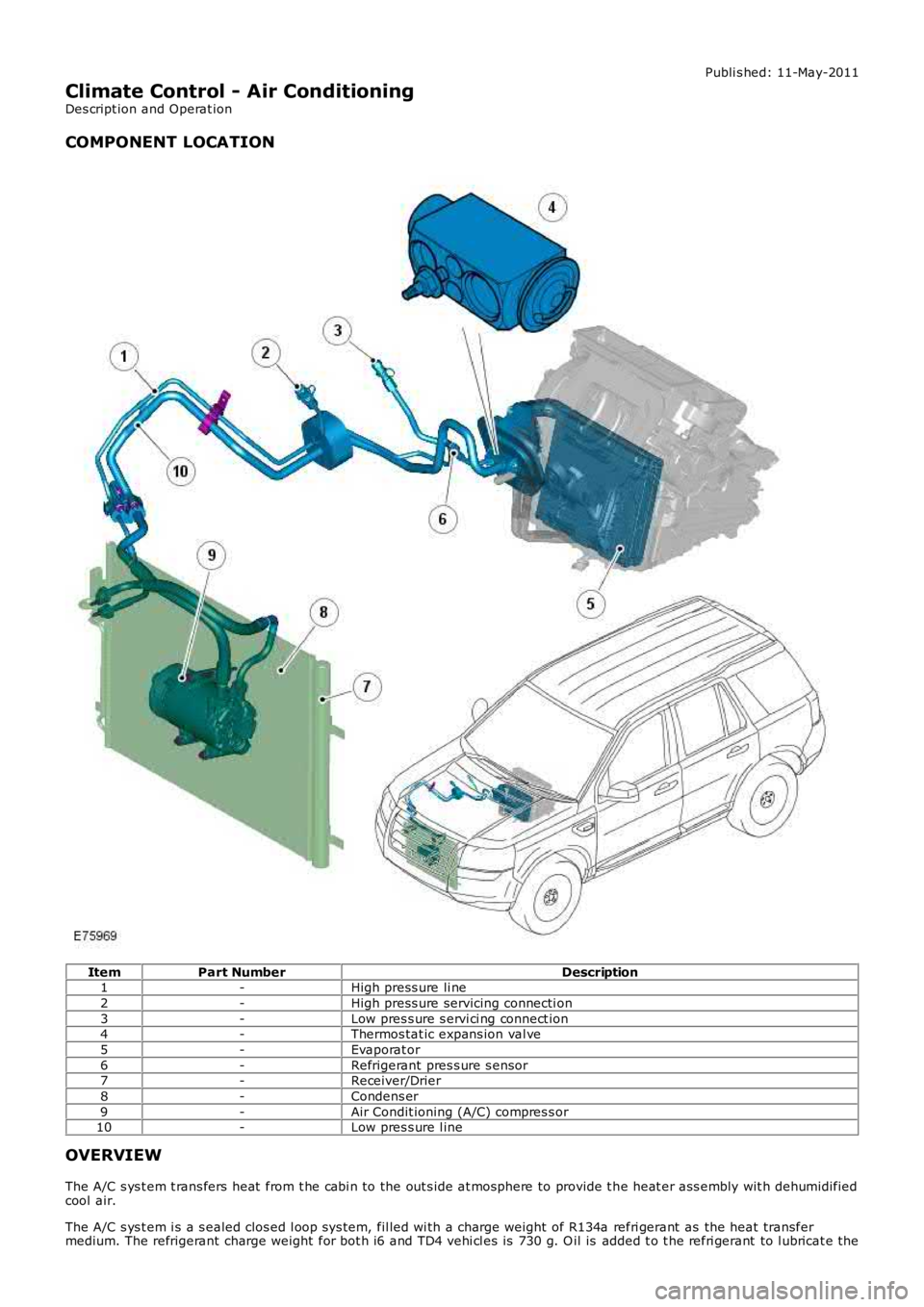
COMPONENT LOCATION
ItemPart NumberDescription1-High press ure li ne
2-High press ure servicing connecti on
3-Low pres s ure s ervi ci ng connect ion4-Thermos tat ic expans ion val ve
5-Evaporat or
6-Refrigerant pres s ure s ensor7-Receiver/Drier
8-Condens er
9-Air Condit ioning (A/C) compres s or10-Low pres s ure l ine
OVERVIEW
The A/C s ys t em t rans fers heat from t he cabi n to the out s ide at mosphere to provide t he heat er ass embly wit h dehumidifiedcool air.
The A/C s ys t em i s a s ealed clos ed l oop sys tem, fil led wi th a charge weight of R134a refri gerant as the heat transfermedium. The refrigerant charge weight for bot h i6 and TD4 vehi cl es is 730 g. O il is added t o t he refri gerant to l ubricat e the
Page 1646 of 3229
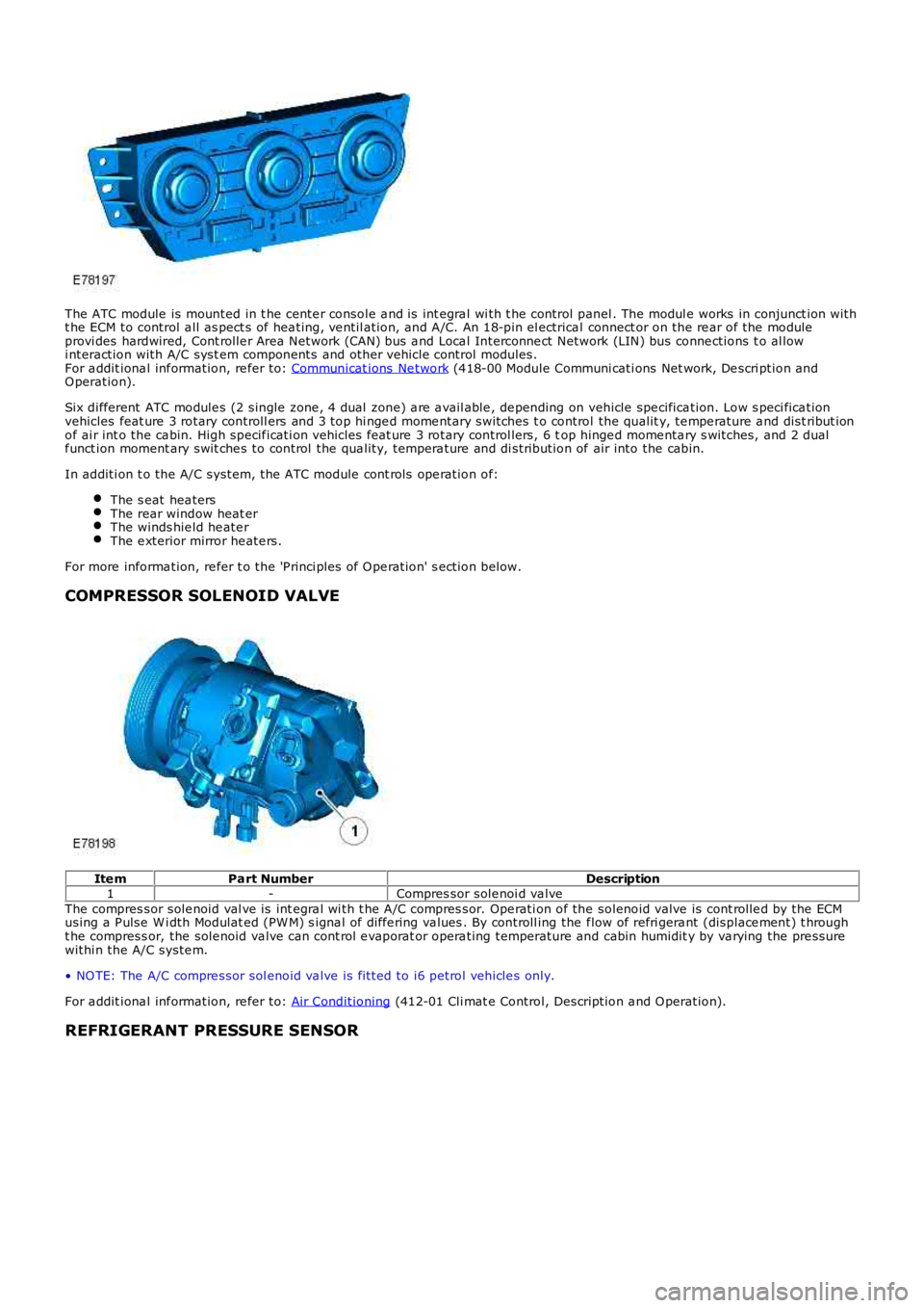
The ATC module is mounted in t he cente r console a nd is int egra l wi th t he control panel . The modul e works in conjunct ion witht he ECM to control a ll as pect s of hea ting, ve ntil ation, and A/C. An 18-pin el ectrical connect or on the re ar of the moduleprovi des hardwired, Cont rolle r Area Network (CAN) bus a nd Loca l Interconne ct Network (LIN) bus conne ctions t o al lowi nteraction with A/C syst em components and other vehicle control modules.For a ddit iona l inf ormation, re fer to: Communicat ions Ne twork (418-00 Module Communi cati ons Net work, De scri ption andO peration).
Six different ATC module s (2 single zone , 4 dual zone) a re a vail able , de pending on vehicle spe cifica tion. Low s peci fica tionvehicles feat ure 3 rotary controll ers and 3 top hi nge d mome ntary switches t o control the qualit y, te mpe rature a nd dist ribut ionof ai r int o the ca bin. High specif icati on vehicles feat ure 3 rotary control lers, 6 top hinge d mome nta ry s witches, and 2 dualf unct ion moment ary swit che s to control the qua lity, tempera ture and di stribution of air into the cabin.
In additi on t o the A/C system, t he ATC module cont rols ope ration of:
The s eat hea tersThe rear window heat erThe winds hie ld he ate rThe e xterior mirror he ate rs.
For more informa tion, re fer t o the 'P rinci ples of O pe ration' s ection below.
COMPRESSOR SOLENOID VALVE
Ite mPart NumberDescription1-Compres sor sole noi d va lveThe compres sor sole noid val ve is int egra l wi th t he A/C compres sor. Ope rati on of the solenoid valve is cont rolle d by the ECMusing a P ulse W i dth Modulat ed (PW M) s igna l of diffe ring va lues . By controll ing the flow of refri gera nt (displace ment) t hrought he compress or, the sole noid va lve can cont rol e vaporat or opera ting temperature and cabin humidit y by va rying the pre ssurewithi n the A/C syste m.
• NO TE: The A/C compre ssor sol enoid va lve is fi tted to i6 petrol vehicle s only.
For a ddit iona l inf ormation, re fer to: Air Conditioning (412-01 Cli mat e Control, Description a nd O peration).
REFRIGERANT PRESSURE SENSOR
Page 1712 of 3229
Publi s hed: 11-May-2011
Climate Control - Air Conditioning (A/C) CompressorI6 3.2L Petrol
Removal and Inst all ati on
Removal
CAUTION: Make s ure that the specified amount of refrigerant oi l is added.
Remove t he cover and dis connect the bat tery ground cabl e.
Refer t o: Specificati ons (414-00 Bat tery and Charging Sys tem -General Informat ion, Specificati ons).
1.
Recover t he air condi ti oni ng (A/C) refri gerant .
Refer t o: Air Condi ti oning (A/C) Sys tem Recovery, Evacuati on andCharging (412-00 Cl imat e Control Sys t em - General Informat ion,General Procedures).
2.
Remove t he engi ne cover.
Refer t o: Engi ne Cover - I6 3.2L Pet rol (501-05 Int eri or Trim andOrnament ati on, Removal and Ins tal lat ion).
3.
Remove t he bat t ery t ray.
Refer t o: Bat t ery Tray (414-01 Bat tery, Mount ing and Cables ,Removal and Ins tall ati on).
4.
Remove t he air cleaner as s embly.
Refer t o: Air Cleaner (303-12A Intake Ai r Dis tribut ion and Fil tering -I6 3.2L Pet rol, Removal and Ins t al lat ion).
5.
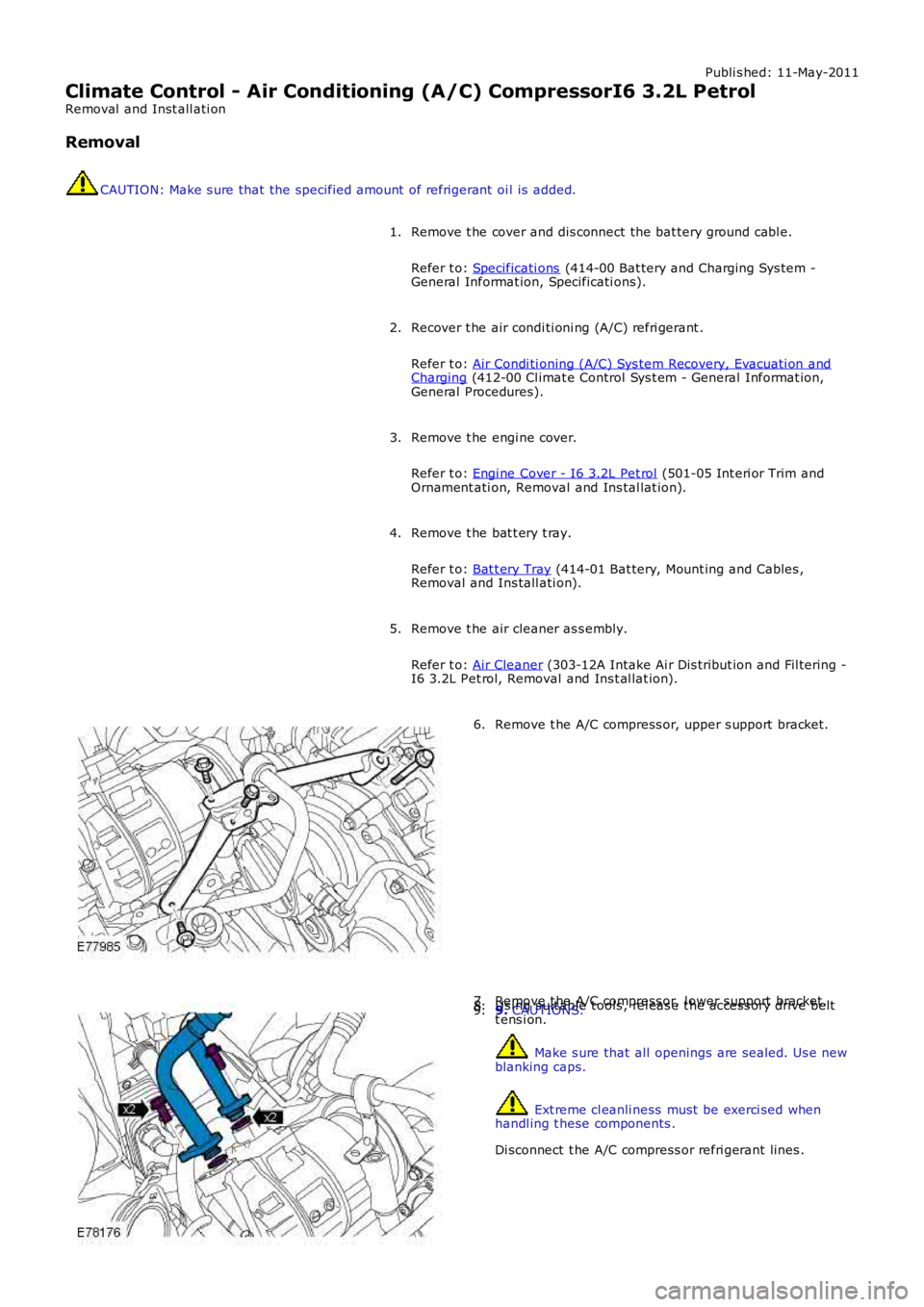
Remove t he A/C compress or, upper s upport bracket.6.
Remove t he A/C compress or, l ower support bracket.7.Us ing s uit able t ools , rel eas e t he acces s ory drive beltt ens i on.8.9. CAUTIONS:
Make s ure that all openings are sealed. Us e newblanking caps.
Ext reme cl eanli ness must be exerci sed whenhandl ing t hese components .
Di sconnect t he A/C compress or refri gerant lines .
9.
Page 1715 of 3229
Publi s hed: 11-May-2011
Climate Control - Air Conditioning (A/C) CompressorTD4 2.2L Diesel
Removal and Inst all ati on
Removal CAUTION: Make s ure that the specified amount of refrigerant oi l is added.
• NOTE: Removal s t eps in t his procedure may cont ain i nst all ati on det ail s.
Di sconnect t he bat t ery ground cable.
Refer t o: Specificati ons (414-00 Bat tery and Charging Sys tem -
General Informat ion, Specificati ons).
1.
Recover t he A/C refrigerant .
Refer t o: Air Condi ti oning (A/C) Sys tem Recovery, Evacuati on and Charging (412-00 Cl imat e Control Sys t em - General Informat ion,
General Procedures).
2. 3.
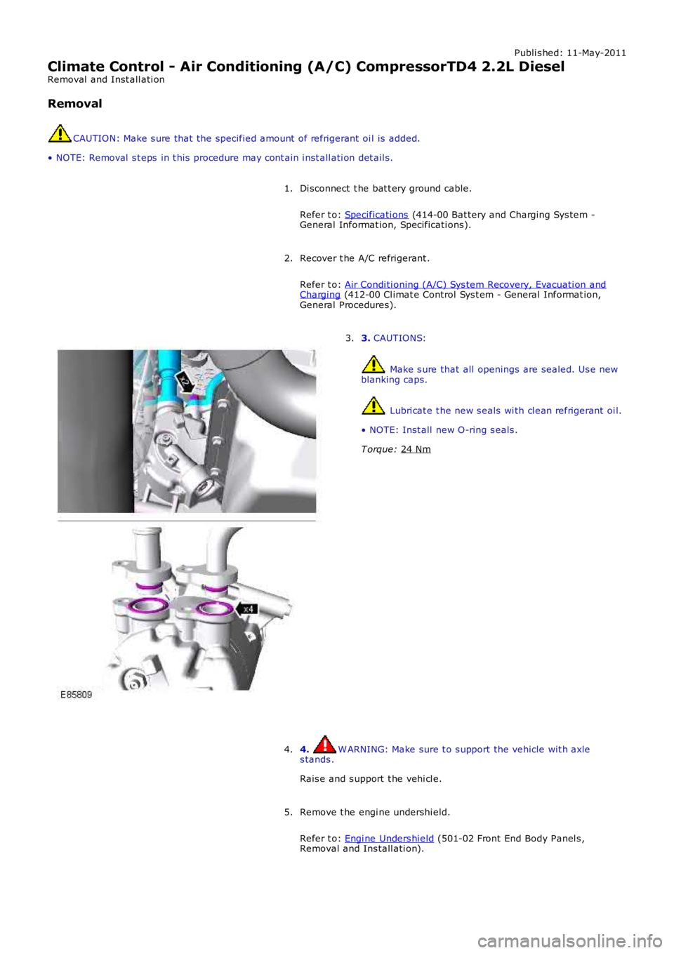
CAUTIONS: Make s ure that all openings are sealed. Us e new
blanking caps. Lubri cat e t he new s eals wi th cl ean refrigerant oi l.
• NOTE: Inst all new O-ring s eals .
T orque: 24 Nm 3.
4. W ARNING: Make sure t o s upport the vehicle wit h axle
s tands .
Rais e and s upport t he vehi cl e.
4.
Remove t he engi ne undershi eld.
Refer t o: Engi ne Unders hi eld (501-02 Front End Body Panel s ,
Removal and Ins tall ati on).
5.
Page 1727 of 3229
Publi s hed: 11-May-2011
Climate Control - Air Conditioning (A/C) Pressure Transducer
Removal and Inst all ati on
Removal
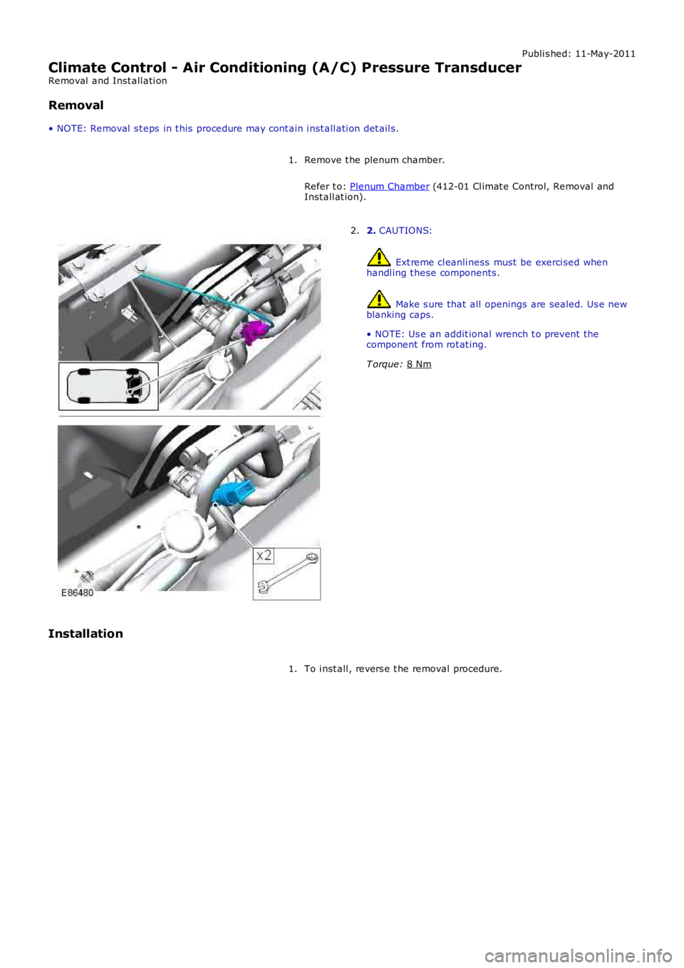
• NOTE: Removal s t eps in t his procedure may cont ain i nst all ati on det ail s.
Remove t he plenum chamber.
Refer t o: Plenum Chamber (412-01 Cl imat e Control, Removal and
Inst all at ion).
1. 2.
CAUTIONS: Ext reme cl eanli ness must be exerci sed when
handl ing t hese components . Make s ure that all openings are sealed. Us e new
blanking caps.
• NOTE: Us e an addit ional wrench t o prevent the
component from rot at ing.
T orque: 8 Nm 2.
Installation To i nst all , revers e t he removal procedure.
1.
Page 2560 of 3229

Publ is hed: 11-May-2011
Front End Sheet Metal Repairs - Fender Apron Panel
Removal and Installation
Removal
• NOTE: The fender apron panel is serviced as a separate weld-on panel. It is an assembly of the fender apron panel
reinforcement, fender apron lower panel and fender apron panel front extension.
• NOTE: The panel is serviced less its weld studs
1. The fender apron panel is replaced in conjunction with:
Front bumper cover
Hood lat ch panel
Both front fenders
Fender apron upper panel
2. Fo r a d d i t i o na l i nf o rma t i o n re l a t i ng t o t hi s re p a i r p ro ce d ure
please see the following:
Fo r a d d i t i o na l i nf o rma t i o n, re f e r t o : Body and Frame
(501-26
Body Repairs - Vehicle Specific Information and Tolerance
Checks, Description and Operation) /
St a nd a rd W o rks ho p P ra ct i ce s
(100-00 Ge ne ra l I nf o rma t i o n,
Description and Operation).
3. Remove the fender apron upper panel.
Fo r a d d i t i o na l i nf o rma t i o n, re f e r t o : Fender Apron Upper Panel
(501-27 Front End Sheet Met al Re pai rs , Removal and
Installation).
4. L H Si d e : Re mo ve t he a i r cl e a ne r.
Fo r a d d i t i o na l i nf o rma t i o n, re f e r t o : Air Cleaner
(303-12A
I nt a ke A i r Di s t ri b ut i o n a nd Fi l t e ri ng - I 6 3. 2L P e t ro l , Re mo va l
and Installation).
5. LH Side: Remove the air intake pipe.
6. LH Side: Remove the bat tery t ray.
Fo r a d d i t i o na l i nf o rma t i o n, re f e r t o : Battery Tray
(414-01
Battery, Mounting and Cables, Removal and Installation).
7. LH Side: Remove the engine lower support insulator.
Fo r a d d i t i o na l i nf o rma t i o n, re f e r t o : Engine Lower Support
Insulator (303-01A Engi ne - I6 3.2L Pet rol, Removal and
Installation).
8. LH Side: Release the battery junction box and position aside.
9. RH Side: Drain the cooling system.
Fo r a d d i t i o na l i nf o rma t i o n, re f e r t o : Cooling Sys tem Draining,
Filling and Bleeding (303-03A Engine Cooling - I6 3.2L Petrol,
General Procedures ).
10. RH Side: Evacuate the A/C system.
Fo r a d d i t i o na l i nf o rma t i o n, re f e r t o : Air Conditioning (A/C)
System Recovery, Evacuation and Charging (412-00 Cl i mat e
Co nt ro l Sys t e m - Ge ne ra l I nf o rma t i o n, Ge ne ra l P ro ce d ure s ).
11. RH Si d e : Re mo ve t he p o we r s t e e ri ng re s e rvo i r.
Fo r a d d i t i o na l i nf o rma t i o n, re f e r t o : P o we r St e e ri ng Fl ui d
Res ervoi r (211-02 Power St eeri ng, Removal and Ins t al lat i on).
12. RH Side: Release the coolant expansion tank and position
aside.
13. RH Side: Remove the engine mounting bracket.
Fo r a d d i t i o na l i nf o rma t i o n, re f e r t o : Engine Mount RH
(303-01A
Engine - I6 3.2L Petrol, Removal and Installation).
14. RH Side: Remove the windshield washer reservoir.
Fo r a d d i t i o na l i nf o rma t i o n, re f e r t o : Windshield Washer
Res ervoi r (501-16 W i pers and W as hers , Removal and
Installation).
15. RH Side: Remove the fender apron A/C pipes.
16. Remove the shock absorber and spring assembly.
Fo r a d d i t i o na l i nf o rma t i o n, re f e r t o : Sho ck A b s o rb e r a nd Sp ri ng
Assembly (204-01 Front Sus pens i on, Removal and
Installation).
17. Release and lay aside the wiring harness.
Page 2564 of 3229
Publ is hed: 11-May-2011
Front End Sheet Metal Repairs - Fender Apron Panel Reinforcement
Removal and Installation
Removal
• NOTE: The fender apron panel reinforcement has to be unpicked from the fender apron panel service panel, it is not
available separately.
• NOTE: The RH panel is serviced less its weld studs 1. T he f e nd e r a p ro n p a ne l re i nf o rce me nt i s re p l a ce d i n
conjunct ion wit h:
Front bumper cover
Hood lat ch panel
Both front fenders
Fender apron upper panel
2. Fo r a d d i t i o na l i nf o rma t i o n re l a t i ng t o t hi s re p a i r p ro ce d ure
please see the following:
Fo r a d d i t i o na l i nf o rma t i o n, re f e r t o : Body and Frame
(501-26
Body Repairs - Vehicle Specific Information and Tolerance
Checks, Description and Operation) /
St a nd a rd W o rks ho p P ra ct i ce s
(100-00 Ge ne ra l I nf o rma t i o n,
Description and Operation).
3. Remove the fender apron upper panel.
Fo r a d d i t i o na l i nf o rma t i o n, re f e r t o : Fender Apron Upper Panel
(501-27 Front End Sheet Met al Re pai rs , Removal and
Installation).
4. Remove the front shock absorber.
Fo r a d d i t i o na l i nf o rma t i o n, re f e r t o : Front Shock Abs orber
(204-01 Front Suspension, Removal and Installation).
5. LH Side: Remove the engine support insulator.
Fo r a d d i t i o na l i nf o rma t i o n, re f e r t o : Engine Upper Support
Insulator (303-01B Engi ne - TD4 2.2L Di es el, Removal and
Installation).
6. LH Side: Remove the bat tery t ray.
Fo r a d d i t i o na l i nf o rma t i o n, re f e r t o : Battery Tray
(414-01
Battery, Mounting and Cables, Removal and Installation).
7. LH Side: Remove the air intake pipe.
8. LH Side: Release the battery junction box and position aside.
9. RH Side: Remove the windshield washer reservoir.
Fo r a d d i t i o na l i nf o rma t i o n, re f e r t o : Windshield Washer
Res ervoi r (501-16 W i pers and W as hers , Removal and
Installation).
10. RH Side: Remove the engine mounting bracket.
Fo r a d d i t i o na l i nf o rma t i o n, re f e r t o : Engine Mount RH
(303-01B
Engine - TD4 2.2L Diesel, Removal and Installation).
11. RH Side: Release the coolant expansion tank and lay it
aside.
12. RH Side: Evacuate the A/C system.
Fo r a d d i t i o na l i nf o rma t i o n, re f e r t o : Air Conditioning (A/C)
System Recovery, Evacuation and Charging (412-00 Cl i mat e
Co nt ro l Sys t e m - Ge ne ra l I nf o rma t i o n, Ge ne ra l P ro ce d ure s ).
13. RH Side: Remove the fender apron A/C pipes.
14. RH Side: Release and lay aside the insulating material at the
bulkhead.
15. Release and lay aside the wiring harness.
Page 2734 of 3229
14
Quick start
L
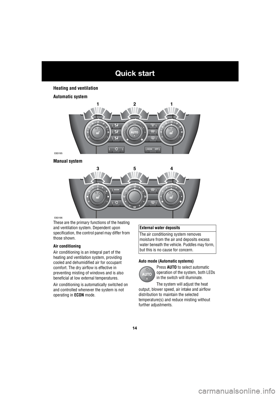
Heating and ventilation
Automatic system
Manual system
These are the primary functions of the heating
and ventilation syst em. Dependent upon
specification, the contro l panel may differ from
those shown.
Air conditioning
Air conditioning is an in tegral part of the
heating and ventilati on system, providing
cooled and dehumidifie d air for occupant
comfort. The dry airflow is effective in
preventing misting of windows and is also
beneficial at low external temperatures.
Air conditioning is automatically switched on
and controlled whenever the system is not
operating in ECON mode. Auto mode (Automatic systems)
Press AUTO to select automatic
operation of the system, both LEDs
in the switch will illuminate.
The system will adjust the heat
output, blower speed, air intake and airflow
distribution to maintain the selected
temperature(s) and re duce misting without
further adjustments.
2121
E83195
2354
E83196
External water deposits
The air conditioning system removes
moisture from the ai r and deposits excess
water beneath the vehicl e. Puddles may form,
but this is no cause for concern.