2006 LAND ROVER FRELANDER 2 gearbox
[x] Cancel search: gearboxPage 102 of 3229
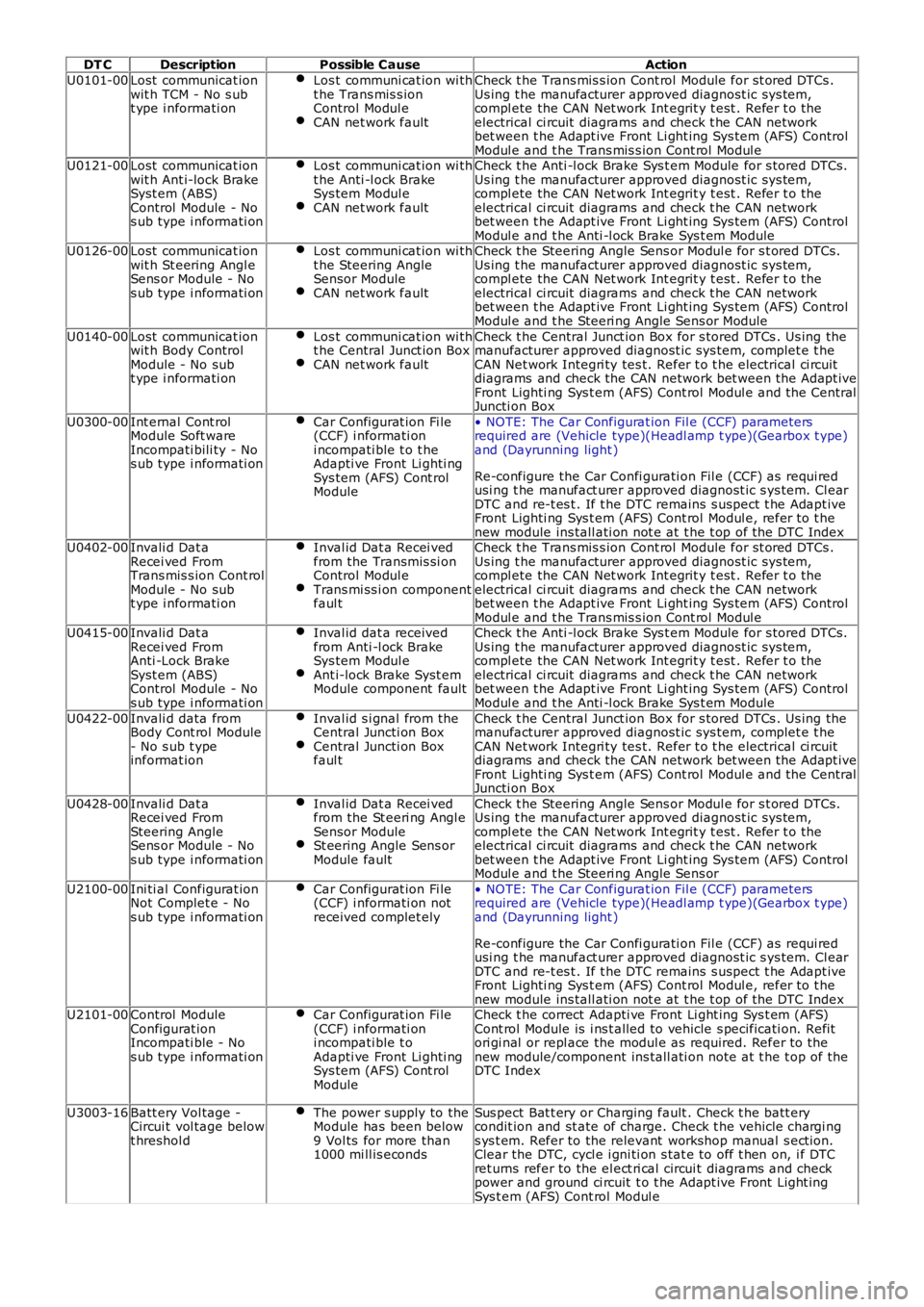
DT CDescriptionPossible CauseAction
U0101-00Lost communicat ionwit h TCM - No s ubt ype i nformati on
Los t communi cat ion wi tht he Trans mis s ionControl Modul eCAN net work fault
Check t he Trans mis s ion Cont rol Module for st ored DTCs .Us ing t he manufacturer approved diagnost ic sys tem,compl ete the CAN Net work Int egrit y t est . Refer t o theelectrical ci rcuit diagrams and check t he CAN networkbet ween t he Adapt ive Front Li ght ing Sys tem (AFS) ControlModul e and t he Trans mis s ion Cont rol Modul eU0121-00Lost communicat ionwit h Ant i-lock BrakeSyst em (ABS)Control Module - Nos ub type i nformati on
Los t communi cat ion wi tht he Anti -l ock BrakeSys tem Modul eCAN net work fault
Check t he Anti -l ock Brake Sys t em Module for s tored DTCs.Us ing t he manufacturer approved diagnost ic sys tem,compl ete the CAN Net work Int egrit y t est . Refer t o theelectrical ci rcuit diagrams and check t he CAN networkbet ween t he Adapt ive Front Li ght ing Sys tem (AFS) ControlModul e and t he Anti -l ock Brake Sys t em ModuleU0126-00Lost communicat ionwit h St eering Angl eSens or Module - Nos ub type i nformati on
Los t communi cat ion wi tht he Steering AngleSensor ModuleCAN net work fault
Check t he Steering Angle Sens or Modul e for s t ored DTCs .Us ing t he manufacturer approved diagnost ic sys tem,compl ete the CAN Net work Int egrit y t est . Refer t o theelectrical ci rcuit diagrams and check t he CAN networkbet ween t he Adapt ive Front Li ght ing Sys tem (AFS) ControlModul e and t he Steeri ng Angle Sens or Module
U0140-00Lost communicat ionwit h Body ControlModule - No subt ype i nformati on
Los t communi cat ion wi tht he Central Junct ion BoxCAN net work fault
Check t he Central Junct ion Box for s tored DTCs . Us ing themanufacturer approved diagnost ic sys tem, complet e t heCAN Net work Integri ty tes t. Refer t o t he electrical ci rcuitdiagrams and check the CAN network bet ween t he Adapt iveFront Lighti ng Sys t em (AFS) Cont rol Modul e and t he CentralJuncti on Box
U0300-00Int ernal Cont rolModule Soft wareIncompati bili ty - Nos ub type i nformati on
Car Configurat ion Fi le(CCF) i nformati oni ncompati ble t o t heAdapti ve Front Li ghti ngSys tem (AFS) Cont rolModule
• NOTE: The Car Configurat ion Fil e (CCF) parametersrequired are (Vehicle type)(Headl amp t ype)(Gearbox t ype)and (Dayrunning light )
Re-configure the Car Confi gurati on Fil e (CCF) as requi redusi ng t he manufact urer approved diagnost ic s ys tem. Cl earDTC and re-t es t . If t he DTC remains s us pect t he Adapt iveFront Lighti ng Sys t em (AFS) Cont rol Modul e, refer t o t henew module ins tall ati on not e at t he t op of the DTC IndexU0402-00Invali d Dat aRecei ved FromTrans mis s ion Cont rolModule - No subt ype i nformati on
Inval id Dat a Recei vedfrom the Transmis si onControl Modul eTrans mi ss i on componentfaul t
Check t he Trans mis s ion Cont rol Module for st ored DTCs .Us ing t he manufacturer approved diagnost ic sys tem,compl ete the CAN Net work Int egrit y t est . Refer t o theelectrical ci rcuit diagrams and check t he CAN networkbet ween t he Adapt ive Front Li ght ing Sys tem (AFS) ControlModul e and t he Trans mis s ion Cont rol Modul eU0415-00Invali d Dat aRecei ved FromAnti -Lock BrakeSyst em (ABS)Control Module - Nos ub type i nformati on
Inval id dat a receivedfrom Anti -l ock BrakeSys tem Modul eAnt i-lock Brake Syst emModule component fault
Check t he Anti -l ock Brake Sys t em Module for s tored DTCs.Us ing t he manufacturer approved diagnost ic sys tem,compl ete the CAN Net work Int egrit y t est . Refer t o theelectrical ci rcuit diagrams and check t he CAN networkbet ween t he Adapt ive Front Li ght ing Sys tem (AFS) ControlModul e and t he Anti -l ock Brake Sys t em Module
U0422-00Invali d data fromBody Cont rol Module- No s ub t ypeinformat ion
Inval id s i gnal from theCentral Juncti on BoxCentral Juncti on Boxfaul t
Check t he Central Junct ion Box for s tored DTCs . Us ing themanufacturer approved diagnost ic sys tem, complet e t heCAN Net work Integri ty tes t. Refer t o t he electrical ci rcuitdiagrams and check the CAN network bet ween t he Adapt iveFront Lighti ng Sys t em (AFS) Cont rol Modul e and t he CentralJuncti on Box
U0428-00Invali d Dat aRecei ved FromSteering AngleSens or Module - Nos ub type i nformati on
Inval id Dat a Recei vedfrom the St eeri ng Angl eSensor ModuleSt eering Angle Sens orModule fault
Check t he Steering Angle Sens or Modul e for s t ored DTCs .Us ing t he manufacturer approved diagnost ic sys tem,compl ete the CAN Net work Int egrit y t est . Refer t o theelectrical ci rcuit diagrams and check t he CAN networkbet ween t he Adapt ive Front Li ght ing Sys tem (AFS) ControlModul e and t he Steeri ng Angle Sens or
U2100-00Ini ti al Configurat ionNot Complet e - Nos ub type i nformati on
Car Configurat ion Fi le(CCF) i nformati on notreceived complet ely
• NOTE: The Car Configurat ion Fil e (CCF) parametersrequired are (Vehicle type)(Headl amp t ype)(Gearbox t ype)and (Dayrunning light )
Re-configure the Car Confi gurati on Fil e (CCF) as requi redusi ng t he manufact urer approved diagnost ic s ys tem. Cl earDTC and re-t es t . If t he DTC remains s us pect t he Adapt iveFront Lighti ng Sys t em (AFS) Cont rol Modul e, refer t o t henew module ins tall ati on not e at t he t op of the DTC IndexU2101-00Control ModuleConfigurat ionIncompati ble - Nos ub type i nformati on
Car Configurat ion Fi le(CCF) i nformati oni ncompati ble t oAdapti ve Front Li ghti ngSys tem (AFS) Cont rolModule
Check t he correct Adapti ve Front Li ght ing Sys t em (AFS)Cont rol Module is i ns t alled to vehicle s pecificati on. Refitori gi nal or repl ace the modul e as required. Refer to thenew module/component ins tall ati on note at t he t op of theDTC Index
U3003-16Batt ery Vol tage -Circui t vol tage belowt hreshol d
The power s upply to theModule has been below9 Vol ts for more than1000 mi ll is econds
Sus pect Bat t ery or Charging fault . Check t he batt erycondit ion and st ate of charge. Check t he vehicle chargi ngs ys t em. Refer to the relevant workshop manual s ect ion.Clear the DTC, cycl e i gni ti on s tat e to off t hen on, i f DTCret urns refer to the el ect ri cal circui t diagrams and checkpower and ground ci rcuit t o t he Adapt ive Front Light ingSys t em (AFS) Cont rol Modul e
Page 169 of 3229

Publi s hed: 11-May-2011
Jacking and Lifting - Vehicle Recovery
Des cript ion and Operat ion
Towing Points
CAUTION: The s ingle towi ng poi nts at t he front and rear of t he vehi cl e are des igned for vehicl e recovery purpos esonly and mus t NOT be used to t ow a trail er or caravan.
The front towi ng eye is acces s ibl e aft er releas ing t he 2 t oggle fast eners s ecuring the t owing eye acces s panel andremovi ng the panel.
CAUTION: Ens ure t hat during t owing, the towi ng att achment does not contact t he bumper.
The rear t owing eye i s acces si ble after rel eas i ng the 2 toggle fas teners securi ng the towing eye access panel and removingt he panel.
CAUTION: This t owing eye s hould onl y be us ed for t owing another vehi cl e or for recovery purpos es .
Towing the vehicle on four wheels
• W ARNINGS:
Ens ure t hat the remote cont rol remai ns docked whil s t the vehicle is being towed. Removi ng the remot e cont rol wi llengage t he s t eering l ock, which wi ll prevent the vehicle from s t eering correct ly.
If the engine cannot be run whi ls t t he vehi cl e i s bei ng t owed, t here wi ll be no power as si s tance for t he s teeri ng orbrakes. Thi s wil l res ult in greater effort bei ng required to st eer or sl ow t he vehi cl e, and greatl y increas ed s toppingdis t ances.
• CAUTIO NS:
The vehicle s hould onl y be t owed wit h four wheels on the ground. Towing wi th two wheel s on t he ground wi ll res ultin serious damage t o t he trans mi s si on.
The vehicle s hould onl y be t owed for a maxi mum of 80 km (50 mil es), at a maximum s peed of 80 km/h (50 mph).Towing for a great er di st ance, or at a higher s peed may res ult i n s eri ous damage t o t he t rans mis s ion.
• NOTE: The recommended recovery met hod is to rais e al l four wheel s.
Towing procedure
1. The vehi cl e s houl d be parked on firm level ground, wi th t he park brake on, and the gear s el ect or in P if an aut omati cgearbox is fit t ed.
2. Secure the towing at t achment from the recovery vehicle to the front t owing eye.
CAUTION: Leavi ng the ignit ion s wi tched on for extended peri ods wil l caus e the bat tery t o drai n.
3. Dock the remote cont rol, and s wi tch on t he igni ti on.
4. Appl y t he foot brake, and s el ect neutral.
5. W i th the foot brake s t ill appli ed, releas e the park brake.
Page 688 of 3229
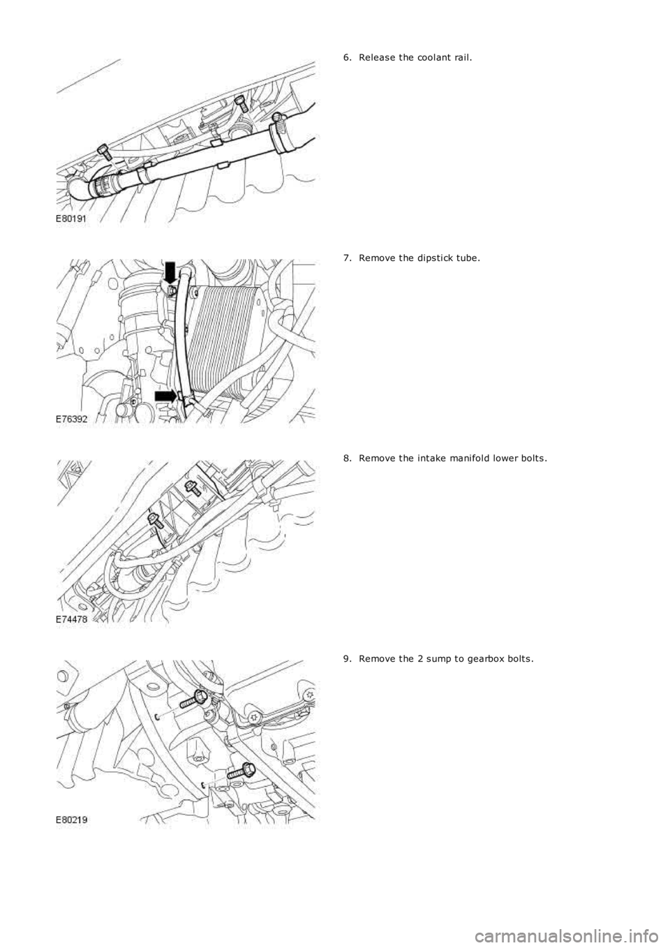
Releas e t he cool ant rail.6.
Remove t he dips ti ck tube.7.
Remove t he int ake mani fol d lower bolt s .8.
Remove t he 2 s ump t o gearbox bolt s .9.
Page 752 of 3229
Publi s hed: 11-May-2011
Engine - TD4 2.2L Diesel -
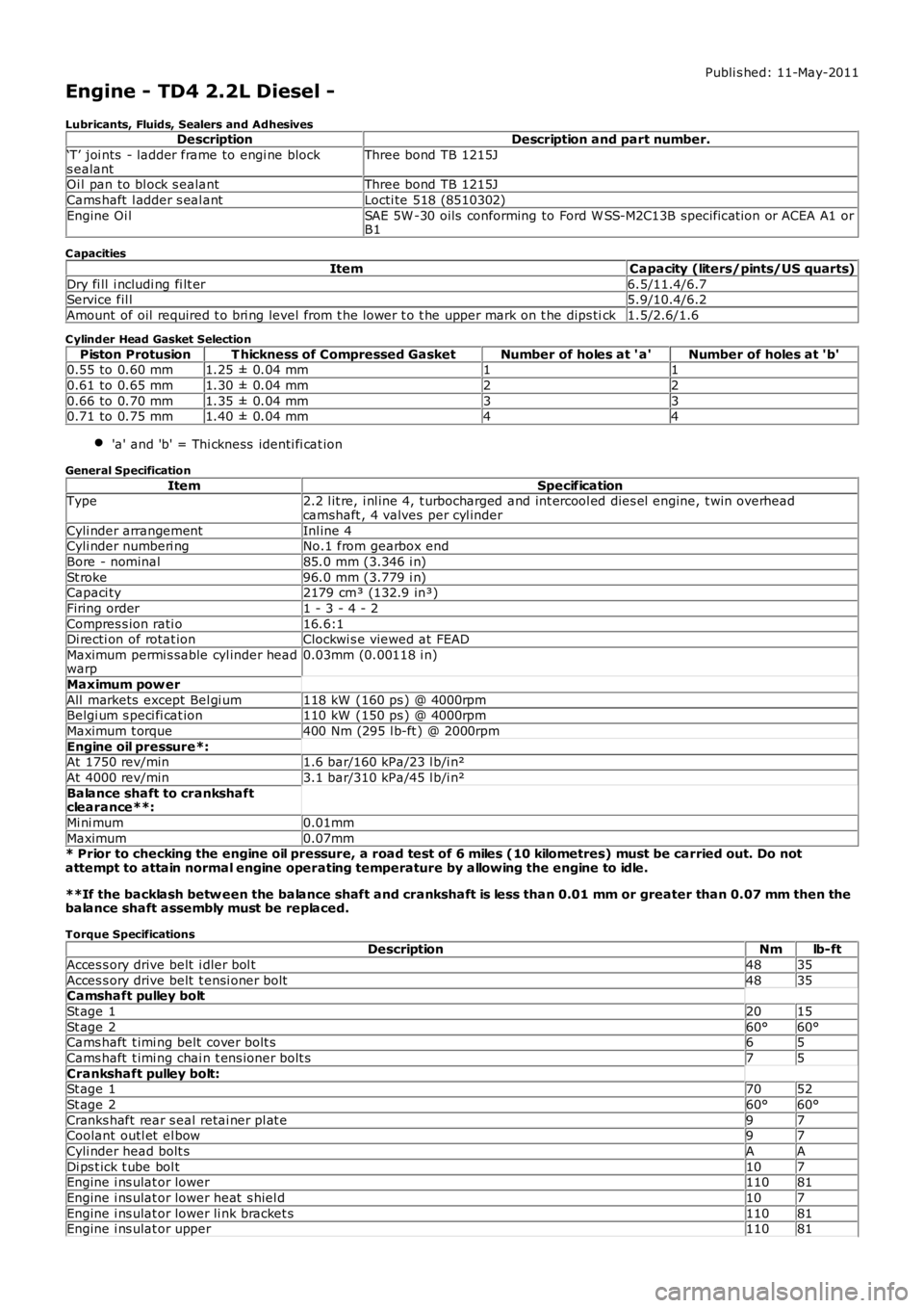
Lubricants, Fluids, Sealers and AdhesivesDescriptionDescription and part number.
‘T’ joi nts - ladder frame to engi ne blocks ealantThree bond TB 1215J
Oi l pan to bl ock s ealantThree bond TB 1215J
Cams haft l adder s eal antLocti te 518 (8510302)
Engine Oi lSAE 5W -30 oils conforming to Ford W SS-M2C13B specificat ion or ACEA A1 orB1
C apacities
ItemCapacity (liters/pints/US quarts)
Dry fi ll i ncludi ng fi lt er6.5/11.4/6.7Service fil l5.9/10.4/6.2
Amount of oil required t o bri ng level from t he lower t o t he upper mark on t he dips tick1.5/2.6/1.6
C ylinder Head Gasket Selection
Piston ProtusionT hickness of Compressed GasketNumber of holes at ' a'Number of holes at 'b'0.55 to 0.60 mm1.25 ± 0.04 mm11
0.61 to 0.65 mm1.30 ± 0.04 mm22
0.66 to 0.70 mm1.35 ± 0.04 mm330.71 to 0.75 mm1.40 ± 0.04 mm44
'a' and 'b' = Thi ckness identi fi cat ion
General Specification
ItemSpecificationType2.2 l it re, i nl ine 4, t urbocharged and int ercool ed dies el engine, t win overheadcamshaft , 4 valves per cyl inder
Cyli nder arrangementInl ine 4Cyli nder numberi ngNo.1 from gearbox end
Bore - nominal85.0 mm (3.346 i n)
St roke96.0 mm (3.779 i n)Capaci ty2179 cm³ (132.9 in³)
Firing order1 - 3 - 4 - 2
Compres s ion rati o16.6:1Di recti on of rotat ionClockwi s e viewed at FEAD
Maximum permi s sable cyl inder headwarp0.03mm (0.00118 i n)
Maximum pow er
All markets except Bel gi um118 kW (160 ps ) @ 4000rpmBelgi um s peci fi cat ion110 kW (150 ps ) @ 4000rpm
Maximum t orque400 Nm (295 l b-ft ) @ 2000rpm
Engine oil pressure*:At 1750 rev/min1.6 bar/160 kPa/23 l b/i n²
At 4000 rev/min3.1 bar/310 kPa/45 l b/i n²
Balance shaft to crankshaftclearance**:
Mi ni mum0.01mm
Maximum0.07mm* Prior to checking the engine oil pressure, a road test of 6 miles (10 kilometres) must be carried out. Do notattempt to attain normal engine operating temperature by allowing the engine to idle.
**If the backlash betw een the balance shaft and crankshaft is less than 0.01 mm or greater than 0.07 mm then thebalance shaft assembly must be replaced.
Torque SpecificationsDescriptionNmlb-ft
Acces s ory drive belt i dler bol t4835
Acces s ory drive belt t ensi oner bolt4835Camshaft pulley bolt
St age 12015
St age 260°60°Cams haft t imi ng belt cover bolt s65
Cams haft t imi ng chai n t ens ioner bolt s75
Crankshaft pulley bolt:St age 17052
St age 260°60°
Cranks haft rear s eal retai ner pl at e97Coolant outl et el bow97
Cyli nder head bolt sAA
Di ps t ick t ube bol t107Engine i ns ulat or lower11081
Engine i ns ulat or lower heat s hiel d107
Engine i ns ulat or lower li nk bracket s11081Engine i ns ulat or upper11081
Page 777 of 3229
ItemPart NumberDescription
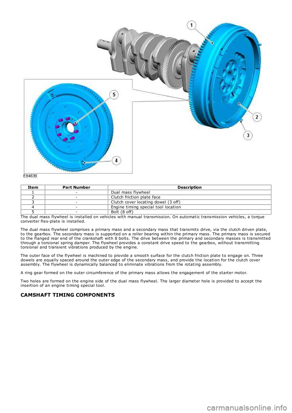
1-Dual mas s flywheel2-Clut ch fricti on plate face
3-Clut ch cover locat ing dowel (3 off)
4-Engi ne ti mi ng special t ool l ocati on5-Bolt (8 off)
The dual mas s flywheel is i nst all ed on vehi cl es wit h manual transmis si on. On automatic t rans mis s ion vehicles , a t orqueconvert er fl ex-plat e is ins tall ed.
The dual mas s flywheel compris es a primary mas s and a s econdary mass that t rans mit s dri ve, vi a the cl utch dri ven plate,t o the gearbox. The s econdary mas s i s s upported on a rol ler bearing wit hi n t he pri mary mass . The pri mary mas s is s ecuredt o the fl anged rear end of t he crankshaft wit h 8 bolt s . The drive bet ween the primary and s econdary mass es i s transmit tedt hrough a t ors ional spring damper. The flywheel provi des a cons t ant drive s peed to the gearbox, wit hout trans mi tt ingt ors ional and t rans ient vibrat ions produced by t he engi ne.
The outer face of t he fl ywheel i s machi ned to provide a smoot h s urface for the cl utch fri ct ion pl at e t o engage on. Threedowels are equal ly s paced around the out er edge of t he s econdary mas s , and provide the l ocati on for t he clut ch coveras sembl y. The flywheel is dynamically bal anced t o eli mi nat e vibrat ions from t he rot at ing as s embly.
A ring gear formed on t he outer circumference of the primary mas s al lows t he engagement of the s t art er motor.
Two holes are formed on t he engine s ide of t he dual mass fl ywheel. The l arger diameter hole is provi ded to accept theins ert ion of an engine ti ming s peci al tool.
CAMSHAFT TIMING COMPONENTS
Page 1368 of 3229
Publi s hed: 11-May-2011
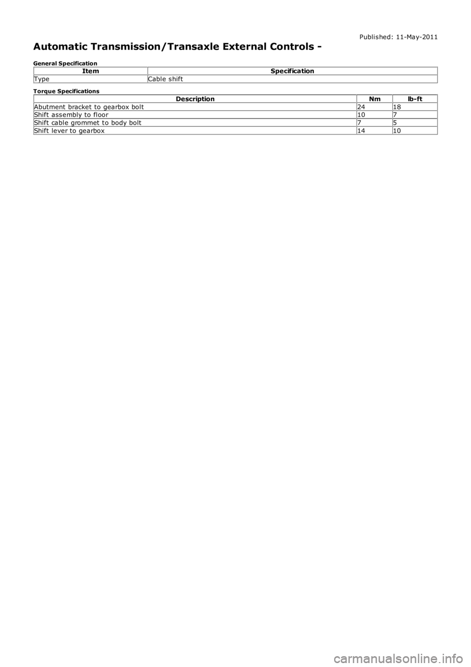
Automatic Transmission/Transaxle External Controls -
General SpecificationItemSpecification
TypeCabl e s hift
Torque Specifications
DescriptionNmlb-ft
Abutment bracket to gearbox bol t2418Shift ass embly to fl oor107
Shift cabl e grommet t o body bolt75
Shift lever to gearbox1410
Page 1471 of 3229
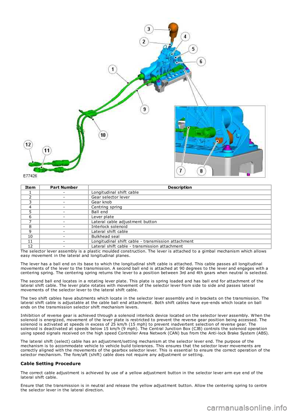
ItemPart NumberDescription
1-Longit udi nal s hift cabl e2-Gear s elect or lever
3-Gear knob
4-Centring spring5-Ball end
6-Lever pl ate
7-Lateral cable adjust ment butt on8-Interlock s ol enoi d
9-Lateral shi ft cabl e
10-Bulkhead s eal11-Longit udi nal s hift cabl e - t ransmis s ion at tachment
12-Lateral shi ft cabl e - t rans mis s ion at t achment
The s elect or lever ass embly is a pl ast ic moulded cons t ructi on. The l ever i s att ached t o a gi mbal mechanis m which all owseasy movement i n t he lat eral and longit udi nal pl anes .
The lever has a ball end on i ts bas e t o which t he l ongi tudinal s hi ft cable i s at tached. This cable pas s es all longit udinalmovements of t he lever to the t rans mi ss i on. A second ball end is at t ached at 90 degrees t o t he lever and engages wit h acent eri ng s pring. The cent eri ng s pring returns the lever t o a pos it ion bet ween 3rd and 4t h gears when neut ral is sel ect ed.
The s econd ball end l ocat es in a rot at ing lever pl ate. This pl at e i s s pring loaded and has bal l end for att achment of t helat eral s hi ft cable. The lever plat e rot ates wi th movement of t he s elect or lever from s ide to si de and pass es l at eralmovements of t he s elect or lever to the l ateral s hift cabl e.
The t wo s hift cables have abutment s which l ocat e in the s elect or l ever as s embl y and i n bracket s on t he t rans mis s ion. Thelat eral s hi ft cable is adjus t abl e at the cable bal l end att achment . Bot h s hift cabl es have eye-ends which l ocat e on ballends on the trans mi s si on s el ect or s hi ft mechanis m levers .
Inhi bi ti on of revers e gear is achieved t hrough a s olenoid i nterlock devi ce locat ed on t he s elect or lever ass embly. W hen thes olenoi d i s energized, movement of t he lever pl ate is rest ri cted t o prevent the revers e gear pos it ion bei ng acces sed. Thes olenoi d i s act ivat ed at speeds in exces s of 25 km/h (15 mph) t o prevent inadvert ent s electi on of revers e gear. Thes olenoi d i s deact ivated at s peeds bel ow 15 km/h (9 mph). The Cent ral Junct ion Box (CJB) control s t he s ol enoi d operat ionus ing s peed si gnal s received on t he high speed Controller Area Network (CAN) bus from t he Ant i-lock Brake Sys tem (ABS).
The lat eral s hi ft (s elect) cable has an adjus t ment/s et t ing mechani s m at t he s elect or lever end. The purpos e of t hemechani sm i s to accommodate vehicl e to vehi cl e buil d tol erances . This ens ures t hat the s elector l ever movements arecorrect ly ali gned wit h t he movement s of t he gearbox s el ect or lever. This i s es sent ial to ens ure the correct operat ion of t hes elect or mechani sm. The fore/aft (s hi ft ) cabl e does not require any adjust ment or s et t ing.
Cable Setting Proced ure
The correct cabl e adjus tment i s achi eved by use of a yel low adjust ment butt on in the s elect or l ever arm eye end of t helat eral s hi ft cable.
Ensure t hat t he t rans mis s ion i s in neut ral and rel ease the yell ow adjus t ment but ton. All ow t he cent eri ng s pring t o centret he sel ect or lever i n t he lat eral direct ion.
Page 2062 of 3229
Publi s hed: 11-May-2011
Anti-Theft - Passive - Anti-Theft - Passive
Diagnosi s and Tes ti ng
Principles of Operation
For a detail ed descripti on of the Pas s ive Ant i-Theft Sys t em (PATS), refer t o t he relevant Des cript ion and Operat ion secti onin the workshop manual.REFER to: Ant i-Theft - Pas s ive (419-01B Anti -Theft - Pas s ive, Descripti on and Operat ion).
Inspection and Verification
The best method t o confirm the correct operat ion of t he Pass i ve Ant i-Theft Syst em (PATS) is t o check t he LED (located i nt he cent er of t he ins t rument panel ). The LED s hould i ll uminate sol id for 3 s econds , when the i gnit ion s tat us is set t o ON,and t hen ext inguis h. Thi s validat es all PATS functi ons (i .e. the key t rans ponder matches a st ored key code, thechal lenge/res ponse sequence bet ween t he res pect ive modules was succes s ful res ult ing in t he EMS being enabled).
Ignition Fails to Operate
Check t hat the key i s correct ly i nserted i nto the s t art cont rol unit (SCU) and that i t is t he correct key for t he vehi cle (Keywil l be ejected from t he SCU i f it is not programmed or from anot her vehicl e). If the vehicle is an aut omati c, ens ure t hatt he Park pos it ion i s s el ect ed and if manual, ens ure it is in t he Neutral pos i ti on.
Check t hat the st art but ton circui t to the Cent ral Juncti on Box (CJB) i s not open circui t or s hort to ground.
Check t hat the CAN network is not mal functi oni ng, i .e. open circuit or s hort circui t. This woul d mean t hat the CJB, ECM andIns t rument Clus t er woul d be unabl e t o communicate. Check thes e modules for relat ed DTCs and refer t o relevant DTCIndex.
Engine Fails to Crank
The immobili zer s t atus i ndi cat ion LED i s dis played i n the bot tom left of the i nst rument pack. W hen the key i s i ns ert ed i nt ot he SCU, t he LED wi ll be t urned on for 3 s econds and t hen turned off. The LED will flas h s lowl y (once every 2 seconds ) i ft he vehi cl e is immobi lis ed (t ransponder not approved). Addit ionall y the di agnos ti c syst em s hould be us ed t o check forDiagnost ic Troubl e Codes (DTCs ) from the CJB, ins trument cl ust er, ECM and the ABS modul e.
One potent ial occurrence for the vehicl e fai ling to crank on an Automat ic Trans mi s sion coul d be due t o t he Locked in parks wit ch.
Check t he Crank reques t circui t from t he CJB t o ECM for short ci rcuit or open circuit .
Check t he St art er Rel ay Circuit .
Check t hat the St eeri ng Col umn Lock (SCL) is operat ing correctl y. Ins erti ng t he key should drive t he SCL t o un-l ock ands teeri ng wheel should move freel y.
Check t he CAN net work i s not malfunct ioning, i.e. the CAN ci rcuit i s open or short ci rcuit . Thi s would mean that t he CJB,ins t rument clus ter, ECM or ABS module would not be abl e t o communicate res ul ti ng in no chal lenge being made from t hemodules for the Immobil is ati on data.
Als o on an Aut omat ic, check the CAN network between t he CJB and the Transmis s ion Control Modul e (TCM). The CJB usest he "LockedInP" s ignal transmit ted by t he TCM to det ermi ne if t he t rans mis s ion i s in Park before all owing crank, the CJBus es a value of 0x01, i f the CJB s ees a value l ess than t his i t wil l not al low crank, and key wil l not be ejected from SCU.
For a manual gearbox t he clut ch pedal has to be de-pres s ed, hence check t he CAN network between t he CJB and t he ECMt o ensure t he cl utch i s depress ed, Clut chPedal Swit ch75pct = TRUE and Cl ut chPedalPress ed2 = True. The Vehicl e wil l notcrank unti l thes e s ignals are s et.
On an Aut omati c vehi cl e, check t he CAN network between t he ABS module and the CJB. The CJB uses a s ignal"BrakePedalActi ve" t o det ermi ne if t he brake pedal has been depres sed in order t o allow t he engine t o crank. The CJB us esa value = TRUE i f the CJB does not receive t hi s s ignal, i t wil l not al low t he crank reques t output.
Engine Cranks But Will Not Start
If the engine i s cranking i t means that t he EMS has pass ed t he authori s at ion required wit h t he CJB. If thi s authori s at ionfai led, the ECM would not engage the s t art er relay. Thi s coul d be confi rmed by verifyi ng t he LED in the l eft of t heIns t rument pack bei ng il lumi nat ed for 3 seconds on Key ins ert ion, or by reading DTCs from t he CJB or t he ECM.
In all cases of s us pected non-st art i s sues , the most l ogical fail ure modes s houl d be el imi nat ed first . i.e.
1. Check al l relevant suppli es and grounds to the relevant modul es are ok.2. Note any unus ual behavi our from other s yst ems /funct ionali ty.3. Note any funct ions t hat are not operati ng as expect ed.
Fault Codes/DTCs
For the vari ous PATS modes of operat ion/fail ures l is ted i n t he t abl e, t he CJB wi ll store a DTC whi ch wil l not be shown t ot he cus t omer.
W hen t he Key i s ins ert ed and ignit ion st atus ON is achieved, if t he s tart aut horis ation pas ses , the LED in t he bott om leftof the ins trument cl us t er will i ll uminate for 3 s econds t hen go off. If st art aut horis ati on fai ls , the LED wil l conti nue to fl as hevery 2 s econds . Pleas e s ee tabl e below for a li s t of fault codes that wil l be s tored under cert ain condi ti ons. For addi ti onalinformat ion.REFER to: St art ing Syst em (303-06A St art ing Sys tem - I6 3.2L Petrol, Di agnos is and Tes ti ng) /