Page 2667 of 3383
PG-26
IPDM E/R (INTELLIGENT POWER DISTRIBUTION MODULE ENGINE ROOM)
Revision: November 20092006 QX56
SchematicEKS00BN7
WKWA3831E
Page 2668 of 3383
IPDM E/R (INTELLIGENT POWER DISTRIBUTION MODULE ENGINE ROOM)PG-27
C
DE
F
G H
I
J
L
M A
B
PG
Revision: November 2009 2006 QX56
IPDM E/R Terminal ArrangementEKS00BN8
WKIA4656E
Page 2669 of 3383

PG-28
IPDM E/R (INTELLIGENT POWER DISTRIBUTION MODULE ENGINE ROOM)
Revision: November 20092006 QX56
IPDM E/R Power/Ground Circuit InspectionEKS00BN9
1. FUSE AND FUSIBLE LINK INSPECTION
Check that the following fusible links or IPDM E/R fuses are not blown.
OK or NG
OK >> GO TO 2.
NG >> Replace fuse or fusible link.
2. POWER CIRCUIT INSPECTION
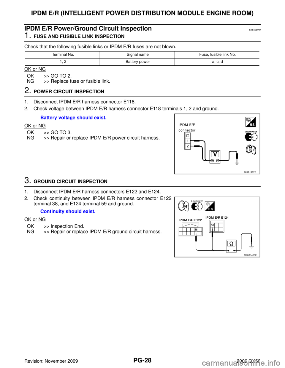
1. Disconnect IPDM E/R harness connector E118.
2. Check voltage between IPDM E/R harness connector E118 terminals 1, 2 and ground.
OK or NG
OK >> GO TO 3.
NG >> Repair or replace IPDM E/R power circuit harness.
3. GROUND CIRCUIT INSPECTION
1. Disconnect IPDM E/R harness connectors E122 and E124.
2. Check continuity between IPDM E/R harness connector E122 terminal 38, and E124 terminal 59 and ground.
OK or NG
OK >> Inspection End.
NG >> Repair or replace IPDM E/R ground circuit harness.
Terminal No. Signal nameFuse, fusible link No.
1, 2 Battery power a, c, d
Battery voltage should exist.
SKIA1987E
Continuity should exist.
WKIA1453E
Page 2670 of 3383

IPDM E/R (INTELLIGENT POWER DISTRIBUTION MODULE ENGINE ROOM)PG-29
C
DE
F
G H
I
J
L
M A
B
PG
Revision: November 2009 2006 QX56
Inspection with CONSULT-II (Self-Diagnosis)EKS00BNA
CAUTION:
If a CONSULT-II is used with no connection of CONSULT-II CONVERTER, malfunctions might be
detected in self-diagnosis depending on which control unit(s) carry out CAN communication.
1. SELF-DIAGNOSIS RESULT CHECK
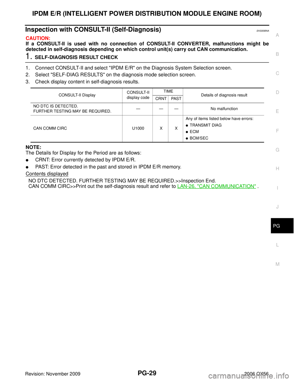
1. Connect CONSULT-II and select "IPDM E/R" on the Diagnosis System Selection screen.
2. Select "SELF-DIAG RESULTS" on the diagnosis mode selection screen.
3. Check display content in self-diagnosis results.
NOTE:
The Details for Display for the Period are as follows:
�CRNT: Error currently detected by IPDM E/R.
�PAST: Error detected in the past and stored in IPDM E/R memory.
Contents displayed
NO DTC DETECTED. FURTHER TESTING MAY BE REQUIRED.>>Inspection End.
CAN COMM CIRC>>Print out the self-diagnosis result and refer to LAN-26, "
CAN COMMUNICATION" .
CONSULT-II DisplayCONSULT-II
display code TIME
Details of diagnosis result
CRNT PAST
NO DTC IS DETECTED.
FURTHER TESTING MAY BE REQUIRED. ———
No malfunction
CAN COMM CIRC U1000 X XAny of items listed below have errors:
�TRANSMIT DIAG
�ECM
�BCM/SEC
Page 2671 of 3383
PG-30
IPDM E/R (INTELLIGENT POWER DISTRIBUTION MODULE ENGINE ROOM)
Revision: November 20092006 QX56
Removal and Installation of IPDM E/REKS00BNB
REMOVAL
1. Disconnect negative battery cable.
2. Remove IPDM E/R upper cover.
3. Release 2 clips and pull IPDM E/R up from case.
4. Disconnect IPDM E/R connectors and remove the IPDM E/R.
INSTALLATION
Installation is in the reverse order of removal.
WKIA1454E
WKIA1696E
Page 2675 of 3383
PG-34
GROUND CIRCUIT
Revision: November 20092006 QX56
ENGINE ROOM HARNESS
WKIA4660E
Page 2678 of 3383
GROUND CIRCUITPG-37
C
DE
F
G H
I
J
L
M A
B
PG
Revision: November 2009 2006 QX56
ENGINE CONTROL HARNESS
WKIA4663E
Page 2682 of 3383

HARNESSPG-41
C
DE
F
G H
I
J
L
M A
B
PG
Revision: November 2009 2006 QX56
HARNESSPFP:24010
Harness LayoutEKS00BND
HOW TO READ HARNESS LAYOUT
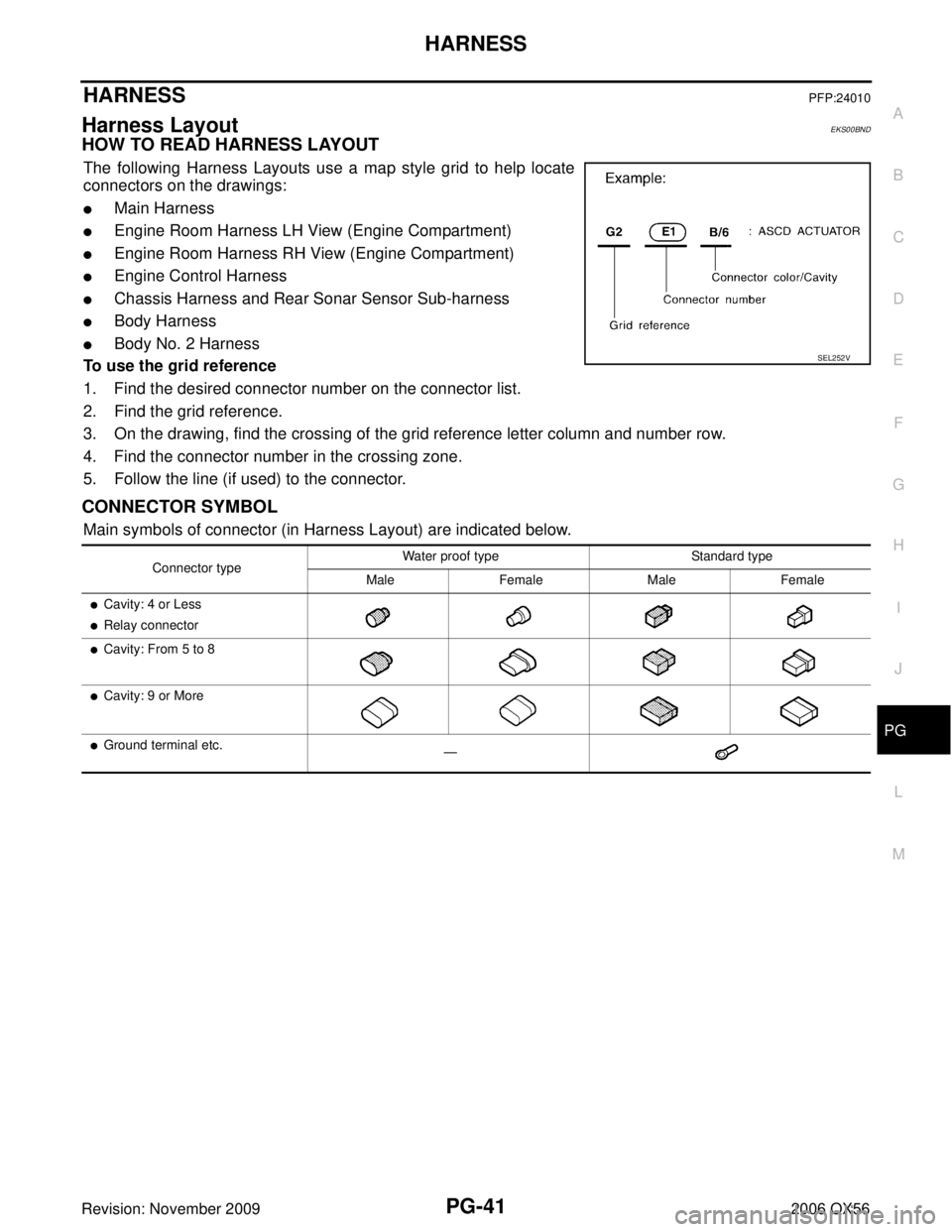
The following Harness Layouts use a map style grid to help locate
connectors on the drawings:
�Main Harness
�Engine Room Harness LH View (Engine Compartment)
�Engine Room Harness RH View (Engine Compartment)
�Engine Control Harness
�Chassis Harness and Rear Sonar Sensor Sub-harness
�Body Harness
�Body No. 2 Harness
To use the grid reference
1. Find the desired connector number on the connector list.
2. Find the grid reference.
3. On the drawing, find the crossing of the grid reference letter column and number row.
4. Find the connector number in the crossing zone.
5. Follow the line (if used) to the connector.
CONNECTOR SYMBOL
Main symbols of connector (in Harness Layout) are indicated below.
SEL252V
Connector type Water proof type Standard type
Male Female Male Female
�Cavity: 4 or Less
�Relay connector
�Cavity: From 5 to 8
�Cavity: 9 or More
�Ground terminal etc. —