Page 3188 of 3383

2. Disconnect t")
TROUBLE DIAGNOSIS FOR SYSTEMTF-83
CE F
G H
I
J
K L
M A
B
TF
Revision: November 2009 2006 QX56
2. CHECK GROUND CIRCUIT
1. Turn ignition switch “OFF”. (Stay for at least 5 seconds.)
2. Disconnect transfer control unit harness connector.
3. Check continuity between transfer control unit harness connec- tor E142 terminals 3, 6, E143 terminal 45 and ground.
Also check harness for short to ground and short to power.
OK or NG
OK >> GO TO 3.
NG >> Repair open circuit or short to ground or short to power in harness or connectors.
3. CHECK ACTUATOR MOTOR POWER SUPPLY CIRCUIT
1. Turn ignition switch “OFF”. (Stay for at least 5 seconds.)
2. Remove transfer shift high relay and transfer shift low relay. Refer to TF-22, "
Location of Electrical Parts" .
3. Check voltage between transfer shift high relay harness connec- tor E46 terminal 5 (A), transfer shift low relay harness connector
E47 terminal 5 (B) and ground.
4. Turn ignition switch “ON”. (Do not start engine.)
5. Check voltage between transfer shift high relay harness connec- tor E46 terminal 5 (A), transfer shift low relay harness connector
E47 terminal 5 (B) and ground.
OK or NG
OK >> GO TO 4.
NG >> Check the following. If any items are damaged, repair or replace damaged parts.
�20A fuse No. 57 located in the fuse and relay box. Refer to PG-4, "POWER SUPPLY ROUTING
CIRCUIT" .
�Harness for short or open between battery, transfer shift high relay harness connector E46 ter-
minal 5 and transfer shift low relay harness connector E47 terminal 5.
Continuity should exist.
SDIA2691E
Connector
Terminal Voltage (Approx.)
E46 5 - Ground
Battery voltage
E47 5 - Ground
WDIA0310E
Connector Terminal Voltage (Approx.)
E46 5 - Ground
Battery voltage
E47 5 - Ground
WDIA0311E
Page 3204 of 3383

TROUBLE DIAGNOSIS FOR SYSTEMTF-99
CE F
G H
I
J
K L
M A
B
TF
Revision: November 2009 2006 QX56
2. CHECK TRANSFER MOTOR RELAY POWER SUPPLY CIRCUIT
1. Turn ignition switch “OFF”. (Stay for at least 5 seconds.)
2. Connect transfer control unit harness connector.
3. Disconnect transfer motor relay.
4. Check voltage between transfer motor relay harness connector terminals and ground.
5. Turn ignition switch “ON”. (Do not start engine.)
6. Check voltage between transfer motor relay harness connector terminals and ground.
OK or NG
OK >> GO TO 3.
NG >> Check the following. If any items are damaged, repair or replace damaged parts.
�20A fuse No. 58 located in the fuse and relay box. Refer to PG-4, "POWER SUPPLY ROUTING
CIRCUIT" .
�10A fuse No. 26 located in the fuse and fusible link box. Refer to PG-4, "POWER SUPPLY
ROUTING CIRCUIT"
�Harness for short or open between battery and transfer motor relay harness connector E154
terminal 5.
�Harness for short or open between transfer shut off relay harness connector E69 terminal 5
and transfer motor relay harness connector E153 terminal 2.
�Battery and ignition switch. Refer to PG-4, "POWER SUPPLY ROUTING CIRCUIT" .
3. CHECK TRANSFER MOTOR RELAY
1. Turn ignition switch “OFF”.
2. Remove transfer motor relay. Refer to TF-22, "
Location of Electrical Parts" .
3. Apply 12V direct current between transfer motor relay terminals 1 and 2.
4. Check continuity between relay terminals 3 and 5.
OK or NG
OK >> GO TO 4.
NG >> Replace the transfer motor relay.
Connector Terminal Voltage (Approx.)
E153 2 - Ground 0V
E154 5 - Ground Battery voltage
WDIA0169E
ConnectorTerminal Voltage (Approx.)
E153 2 - Ground
Battery voltage
E154 5 - Ground
WDIA0170E
Condition Continuity
12V direct current supply between terminals 1 and 2 Yes
OFF No
LDIA0098E
Page 3331 of 3383

WW-4
FRONT WIPER AND WASHER SYSTEM
Revision: November 20092006 QX56
FRONT WIPER AND WASHER SYSTEMPFP:28810
Components Parts and Harness Connector LocationEKS00BDS
System DescriptionEKS00BDT
�Both front wiper relays are located in the IPDM E/R (intelligent power distribution module engine room).
�The wiper switch (combination switch) is composed of a combination of 5 output terminals and 5 input ter-
minals. Terminal combination status is read by the BCM when the wiper switch is turned ON.
�BCM controls front wiper LO, HI, and INT (intermittent) operation.
�IPDM E/R (intelligent power distribution module engine room) operates the wiper motor according to CAN
communication signals from the BCM.
Power is supplied at all times
�through 50A fusible link (letter f , located in the fuse and fusible link box)
�to BCM terminal 70, and
�through 30A fuse (No. 39, located in the IPDM E/R)
�to front wiper relay (located in the IPDM E/R).
With the ignition switch in ON or START position, power is supplied
�through 10A fuse (No. 9, located in the fuse block J/B)
�to combination switch terminal 14, and
�through 10A fuse (No. 59 located in the fuse and relay box)
�to BCM terminal 38.
Ground is supplied
WKIA5719E
1. IPDM E/R E118, E119, E120, E121, E122, E123,
E124 2. Air cleaner case 3. Front and rear washer motor connec-
tor
E105
4. Washer fluid reservoir 5. Front wiper motor E236. Combination switch (wiper switch)
M28
7. BCM M18, M20
Page 3359 of 3383
WW-32
REAR WIPER AND WASHER SYSTEM
Revision: November 20092006 QX56
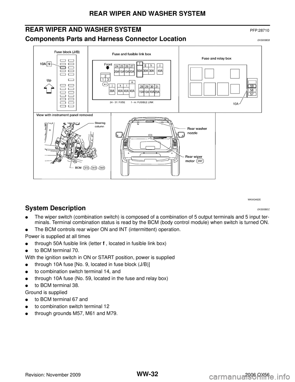
REAR WIPER AND WASHER SYSTEMPFP:28710
Components Parts and Harness Connector LocationEKS00BEB
System DescriptionEKS00BEC
�The wiper switch (combination switch) is composed of a combination of 5 output terminals and 5 input ter-
minals. Terminal combination status is read by the BCM (body control module) when switch is turned ON.
�The BCM controls rear wiper ON and INT (intermittent) operation.
Power is supplied at all times
�through 50A fusible link (letter f , located in fusible link box)
�to BCM terminal 70.
With the ignition switch in ON or START position, power is supplied
�through 10A fuse [No. 9, located in fuse block (J/B)]
�to combination switch terminal 14, and
�through 10A fuse (No. 59, located in the fuse and relay box)
�to BCM terminal 38.
Ground is supplied
�to BCM terminal 67 and
�to combination switch terminal 12
�through grounds M57, M61 and M79.
WKIA3462E