Page 319 of 3383

AT-244
TRANSMISSION ASSEMBLY
Revision: November 20092006 QX56
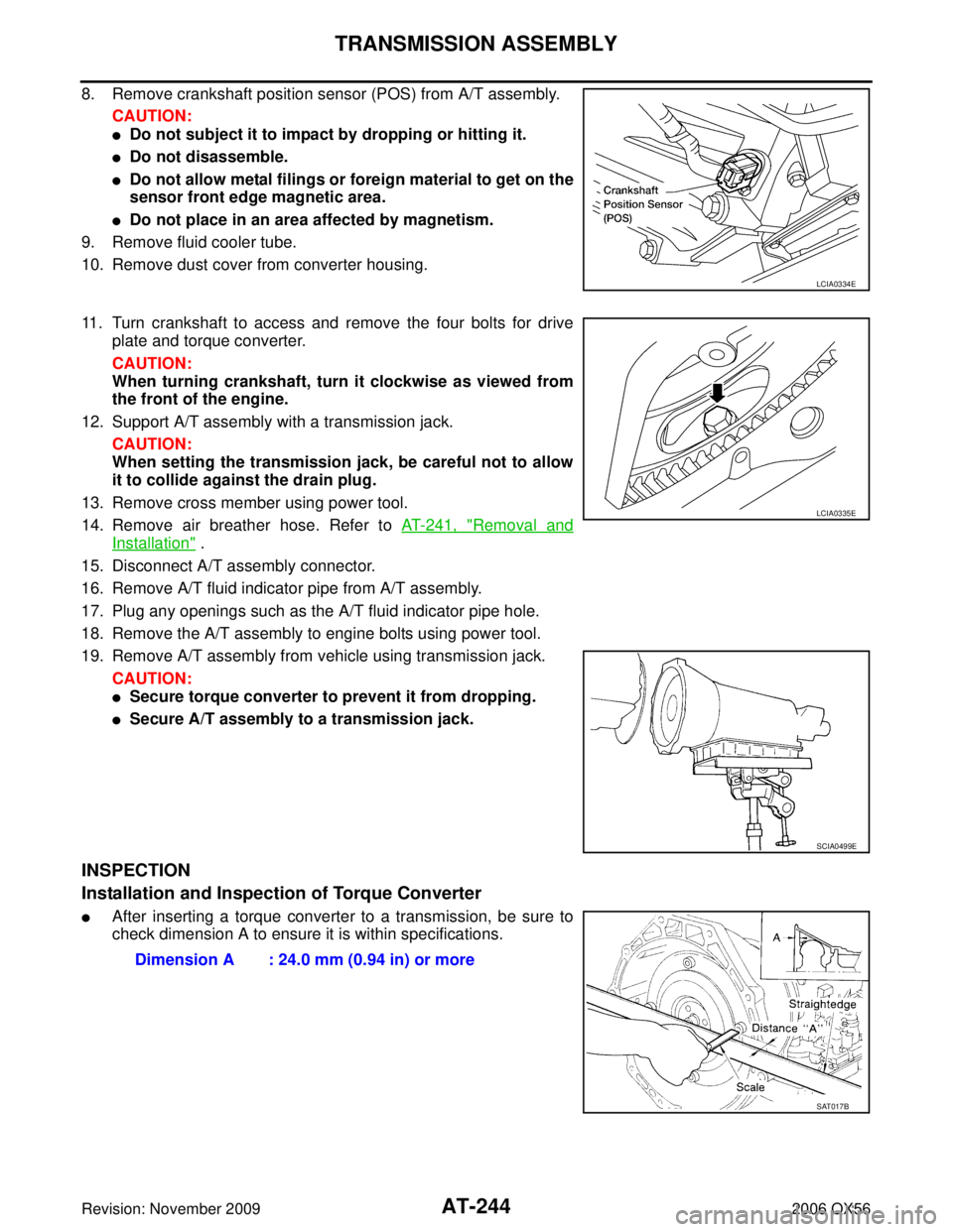
8. Remove crankshaft position sensor (POS) from A/T assembly.
CAUTION:
�Do not subject it to impact by dropping or hitting it.
�Do not disassemble.
�Do not allow metal filings or foreign material to get on the
sensor front edge magnetic area.
�Do not place in an area affected by magnetism.
9. Remove fluid cooler tube.
10. Remove dust cover from converter housing.
11. Turn crankshaft to access and remove the four bolts for drive plate and torque converter.
CAUTION:
When turning crankshaft, turn it clockwise as viewed from
the front of the engine.
12. Support A/T assembly with a transmission jack. CAUTION:
When setting the transmission jack, be careful not to allow
it to collide against the drain plug.
13. Remove cross member using power tool.
14. Remove air breather hose. Refer to AT- 2 4 1 , "
Removal and
Installation" .
15. Disconnect A/T assembly connector.
16. Remove A/T fluid indicator pipe from A/T assembly.
17. Plug any openings such as the A/T fluid indicator pipe hole.
18. Remove the A/T assembly to engine bolts using power tool.
19. Remove A/T assembly from vehicle using transmission jack. CAUTION:
�Secure torque converter to prevent it from dropping.
�Secure A/T assembly to a transmission jack.
INSPECTION
Installation and Inspection of Torque Converter
�After inserting a torque converter to a transmission, be sure to
check dimension A to ensure it is within specifications.
LCIA0334E
LCIA0335E
SCIA0499E
Dimension A : 24.0 mm (0.94 in) or more
SAT017B
Page 322 of 3383

TRANSMISSION ASSEMBLYAT-247
DE
F
G H
I
J
K L
M A
B
AT
Revision: November 2009 2006 QX56
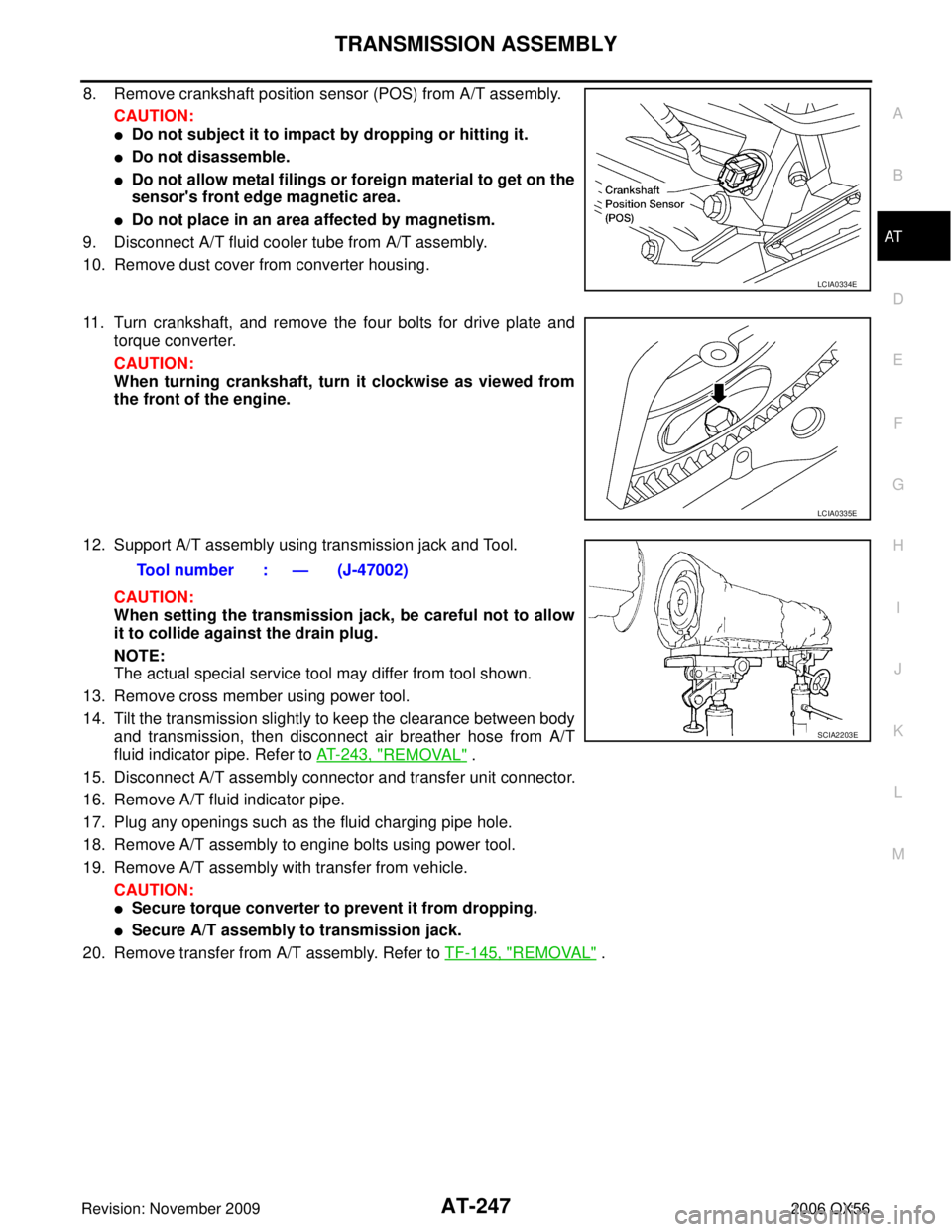
8. Remove crankshaft position sensor (POS) from A/T assembly.
CAUTION:
�Do not subject it to impact by dropping or hitting it.
�Do not disassemble.
�Do not allow metal filings or foreign material to get on the
sensor's front edge magnetic area.
�Do not place in an area affected by magnetism.
9. Disconnect A/T fluid cooler tube from A/T assembly.
10. Remove dust cover from converter housing.
11. Turn crankshaft, and remove the four bolts for drive plate and torque converter.
CAUTION:
When turning crankshaft, turn it clockwise as viewed from
the front of the engine.
12. Support A/T assembly using transmission jack and Tool. CAUTION:
When setting the transmission jack, be careful not to allow
it to collide against the drain plug.
NOTE:
The actual special service tool may differ from tool shown.
13. Remove cross member using power tool.
14. Tilt the transmission slightly to keep the clearance between body and transmission, then disconnect air breather hose from A/T
fluid indicator pipe. Refer to AT- 2 4 3 , "
REMOVAL" .
15. Disconnect A/T assembly connector and transfer unit connector.
16. Remove A/T fluid indicator pipe.
17. Plug any openings such as the fluid charging pipe hole.
18. Remove A/T assembly to engine bolts using power tool.
19. Remove A/T assembly with transfer from vehicle. CAUTION:
�Secure torque converter to prevent it from dropping.
�Secure A/T assembly to transmission jack.
20. Remove transfer from A/T assembly. Refer to TF-145, "
REMOVAL" .
LCIA0334E
LCIA0335E
Tool number : — (J-47002)
SCIA2203E
Page 460 of 3383

TROUBLE DIAGNOSISATC-59
C
DE
F
G H
I
K L
M A
B
AT C
Revision: November 2009 2006 QX56
CHECKING TEMPERATURE INCREASE
1. Rotate temperature control dial clockwise (driver side or passenger side) until 32°C (90 °F) is displayed.
2. Check for hot air at appropriate discharge air outlets.
If NG, listen for sound of air mix door motor operation. If OK, go to trouble diagnosis procedure for ATC-128,
"Insufficient Heating" . If air mix door motor appears to be malfunctioning, go to AT C - 7 2 , "DIAGNOSTIC PRO-
CEDURE FOR AIR MIX DOOR MOTOR (DRIVER)" or AT C - 7 6 , "DIAGNOSTIC PROCEDURE FOR AIR MIX
DOOR MOTOR (PASSENGER)" .
If OK, continue with next check.
CHECK A/C SWITCH
1. Press A/C switch when AUTO switch is ON, or in manual mode.
2. A/C switch indicator will turn ON.
�Confirm that the compressor clutch engages (sound or visual inspection).
NOTE:
If current mode setting is DEF or D/F, compressor clutch may already be engaged.
If NG, go to trouble diagnosis procedure for AT C - 11 5
.
If OK, continue with next check.
CHECKING AUTO MODE
1. Press AUTO switch.
2. Display should indicate AUTO.
�If ambient temperature is warm, and selected temperature is cool, confirm that the compressor clutch
engages (sound or visual inspection). (Discharge air and blower speed will depend on ambient, in-vehi-
cle, and set temperatures.)
If NG, go to trouble diagnosis procedure for AT C - 6 1 , "
Power Supply and Ground Circuit for Front Air Control" ,
then if necessary, trouble diagnosis procedure for AT C - 11 5 , "
Magnet Clutch Circuit" .
If all operational checks are OK (symptom cannot be duplicated), go to malfunction Simulation Tests in AT C -
39, "How to Perform Trouble Diagnosis for Quick and Accurate Repair" and perform tests as outlined to simu-
late driving conditions environment. If symptom appears. Refer to AT C - 3 9 , "
How to Perform Trouble Diagnosis
for Quick and Accurate Repair" , AT C - 3 9 , "SYMPTOM TABLE" and perform applicable trouble diagnosis pro-
cedures.
Page 2566 of 3383

ILLUMINATIONLT-159
C
DE
F
G H
I
J
L
M A
B
LT
Revision: November 2009 2006 QX56
�to front room/map lamp assembly (console box illumination) terminal 8
�to AV switch terminal 4
�to hazard switch terminal 4
�to audio unit terminal 7
�to rear sonar system OFF switch terminal 4
�to 4WD switch terminal 8 (with 4-wheel drive)
�to front air control terminal 24
�to rear power vent window switch terminal 6
�to DVD player terminal 10 (with DVD entertainment system)
�to pedal adjusting switch terminal 6
�to A/T device terminal 12
�to front heated seat switch LH and RH terminal 6
�to VDC OFF switch terminal 4
�to tow mode switch terminal 4
�to headlamp aiming switch terminal 4
�to clock terminal 4 and
�to combination meter terminal 18.
Ground is supplied
�to illumination control switch terminal 3
�to glove box lamp terminal 2
�to display control unit terminal 3
�to rear heated seat switches terminal 6
�to electric brake (pre-wiring) terminal 1 (with trailer tow) and
�to compass and thermometer terminal 7
�through grounds M57, M61 and M79, and
�to NAVI control unit terminal 1
�to rear air control terminal 3 and
�to rear audio remote control unit terminal 15
�through grounds B117 and B132.
With power and ground supplied, illumination lamps illuminate.
EXTERIOR LAMP BATTERY SAVER CONTROL
When the combination switch (lighting switch) is in the 1ST or 2ND position (or if auto light system is acti-
vated), and the ignition switch is turned from ON or ACC to OFF, the battery saver control function is activated.
Under this condition, the illumination lamps remain illuminated for 5 minutes, then the illumination lamps are
turned off.
When the lighting switch is turned from OFF to 1ST or 2ND position (or if auto light system is activated) after
illumination lamps are turned off by the battery saver control, the illumination lamps illuminate again.
Exterior lamp battery saver control mode can be changed by the function setting of CONSULT-II.
CAN Communication System DescriptionEKS00BBK
Refer to LAN-26, "CAN COMMUNICATION" .