Page 2476 of 3383

FRONT FOG LAMPLT-69
C
DE
F
G H
I
J
L
M A
B
LT
Revision: November 2009 2006 QX56
FRONT FOG LAMPPFP:26150
Component Parts and Harness Connector LocationEKS00B9B
System DescriptionEKS00B9C
Control of the fog lamps is dependent upon the position of the combination switch (lighting switch). The light-
ing switch must be in the 2ND position or AUTO position (LOW beam is ON) for front fog lamp operation.
When the lighting switch is placed in the fog lamp position, the BCM (body control module) receives input sig-
nal requesting the fog lamps to illuminate. When the headlamps are illuminated, this input signal is communi-
cated to the IPDM E/R (intelligent power distribution module engine room) across the CAN communication
lines. The CPU (central processing unit) of the IPDM E/R controls the front fog lamp relay coil. When acti-
vated, this relay directs power to the front fog lamps.
OUTLINE
Power is supplied at all times
�to ignition relay, located in the IPDM E/R, and
�to front fog lamp relay, located in the IPDM E/R, and
�through 20A fuse (No. 53, located in the IPDM E/R)
�to CPU of the IPDM E/R, and
�through 50A fusible link (letter f , located in the fuse and fusible link box)
�to BCM terminal 70.
When the ignition switch is in ON or START position, power is supplied
�to ignition relay, located in the IPDM E/R, and
�through 10A fuse (No. 59, located in the fuse and relay box)
�to BCM terminal 38.
Ground is supplied
�to BCM terminal 67
�through grounds M57, M61 and M79, and
�to IPDM E/R terminals 38 and 59
WKIA3466E
Page 2487 of 3383

LT-80
TURN SIGNAL AND HAZARD WARNING LAMPS
Revision: November 20092006 QX56
TURN SIGNAL AND HAZARD WARNING LAMPSPFP:26120
Component Parts and Harness Connector LocationEKS00B9P
System DescriptionEKS00B9Q
OUTLINE
Power is supplied at all times
�through 50A fusible link (letter f , located in the fuse and fusible link box)
�to BCM (body control module) terminal 70, and
�through 10A fuse [No. 19, located in the fuse block (J/B)]
�to combination meter terminal 8.
TURN SIGNAL OPERATION
When the ignition switch is in the ON or START position, power is supplied
�through 10A fuse (No. 59, located in the fuse and relay box)
�to BCM terminal 38, and
�through 10A fuse [No. 14, located in the fuse block (J/B)]
�to combination meter terminal 24.
Ground is supplied
�to BCM terminal 67 and
�to combination meter terminal 17
�through grounds M57, M61 and M79.
LH Turn
When the turn signal switch is moved to the left position, the BCM, interpreting it as turn signal is ON, outputs
turn signal from BCM terminal 60.
The BCM supplies power
�through BCM terminal 60
�to front turn/fog lamp LH terminal 2
WKIA3554E
Page 2518 of 3383

PARKING, LICENSE PLATE AND TAIL LAMPSLT-111
C
DE
F
G H
I
J
L
M A
B
LT
Revision: November 2009 2006 QX56
PARKING, LICENSE PLATE AND TAIL LAMPSPFP:26550
Component Parts and Harness Connector LocationEKS00BAK
System DescriptionEKS00BAL
Control of the parking, license plate, and tail lamp operation is dependent upon the position of the lighting
switch (combination switch). When the lighting switch is placed in the 1ST position, the BCM (body control
module) receives input signal requesting the parking, license plate, side marker and tail lamps to illuminate.
This input signal is communicated to the IPDM E/R (intelligent power distribution module engine room) across
the CAN communication lines. The CPU (central processing unit) of the IPDM E/R controls the tail lamp relay
coil. This relay, when energized, directs power to the parking, license plate and tail lamps, which then illumi-
nate.
Power is supplied at all times
�to ignition relay, located in the IPDM E/R, and
�to tail lamp relay, located in the IPDM E/R, and
�through 20A fuse (No. 53, located in the IPDM E/R)
�to CPU of the IPDM E/R, and
�through 50A fusible link (letter f , located in the fuse and fusible link box)
�to BCM terminal 70.
With the ignition switch in the ON or START position, power is supplied
�through 10A fuse (No. 59, located in the fuse and relay box)
�to BCM terminal 38
�to ignition relay, located in the IPDM E/R, and
Ground is supplied
�to BCM terminal 67
�through grounds M57, M61 and M79, and
�to IPDM E/R terminals 38 and 59
�through grounds E9, E15 and E24.
WKIA3468E
Page 2533 of 3383

LT-126
TRAILER TOW
Revision: November 20092006 QX56
TRAILER TOWPFP:93020
Component Parts and Harness Connector LocationEKS00BB1
System DescriptionEKS00BB2
Power is supplied at all times
�to ignition relay, located in the IPDM E/R (intelligent power distribution module engine room), and
�through 50A fusible link (letter f , located in the fuse and fusible link box)
�to BCM (body control module) terminal 70, and
�through 10A fuse (No. 32, located in the IPDM E/R)
1. Fuse and fusible link box2. IPDM E/R fuse layout 3. Fuse and relay box
4. IPDM E/R E118, E119, E120, E121, E122, E123, E124 5. A. Steering column
B. Data link connector M22
C. BCM M18, M19, M20
(View with instrument lower panel
LH removed) 6. A. Trailer turn relay LH E156
B. Battery
C. Trailer tow relay 2 E140
D. Trailer turn relay RH E157
7. A. Trailer tow relay 1 M51 B. Electric brake (pre-wiring) M76
(View with instrument lower panel
LH removed) 8. Trailer connector C2
9. Combination switch (lighting switch)
M28
WKIA4616E
Page 2564 of 3383

ILLUMINATIONLT-157
C
DE
F
G H
I
J
L
M A
B
LT
Revision: November 2009 2006 QX56
ILLUMINATIONPFP:27545
Component Parts and Harness Connector LocationEKS00BBI
System DescriptionEKS00BBJ
Control of the illumination lamps operation is dependent upon the position of the lighting switch (combination
switch). When the lighting switch is placed in the 1ST or 2ND position (or if the auto light system is activated)
the BCM (body control module) receives input signal requesting the illumination lamps to illuminate. This input
signal is communicated to the IPDM E/R (intelligent power distribution module engine room) across the CAN
communication lines. The CPU (central processing unit) of the IPDM E/R controls the tail lamp relay coil. This
relay, when energized, directs power to the illumination lamps, which then illuminate.
Power is supplied at all times
�to ignition relay, located in the IPDM E/R, and
�to tail lamp relay, located in the IPDM E/R, and
�through 50A fusible link (letter f , located in the fuse and fusible link box)
�to BCM terminal 70, and
�through 20A fuse (No. 53, located in the IPDM E/R)
�to CPU of the IPDM E/R, and
�through 10A fuse [No.19, located in fuse block (J/B)]
WKIA3471E
Page 2785 of 3383
RF-10
SUNROOF
Revision: November 20092006 QX56
SUNROOFPFP:91210
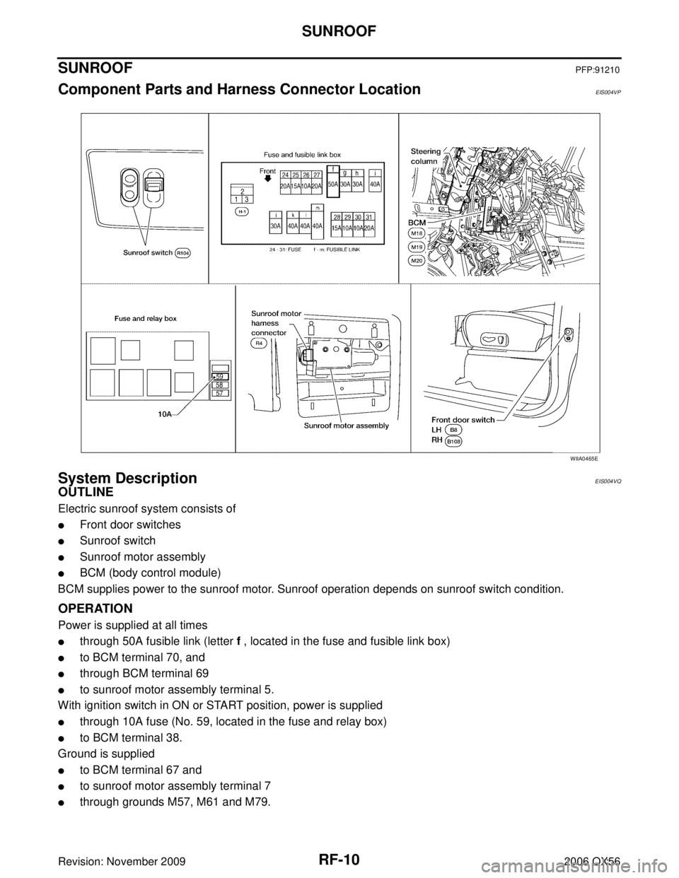
Component Parts and Harness Connector LocationEIS004VP
System DescriptionEIS004VQ
OUTLINE
Electric sunroof system consists of
�Front door switches
�Sunroof switch
�Sunroof motor assembly
�BCM (body control module)
BCM supplies power to the sunroof motor. Sunroof operation depends on sunroof switch condition.
OPERATION
Power is supplied at all times
�through 50A fusible link (letter f , located in the fuse and fusible link box)
�to BCM terminal 70, and
�through BCM terminal 69
�to sunroof motor assembly terminal 5.
With ignition switch in ON or START position, power is supplied
�through 10A fuse (No. 59, located in the fuse and relay box)
�to BCM terminal 38.
Ground is supplied
�to BCM terminal 67 and
�to sunroof motor assembly terminal 7
�through grounds M57, M61 and M79.
WIIA0465E
Page 2793 of 3383

RF-18
SUNROOF
Revision: November 20092006 QX56
BCM Power Supply and Ground Circuit CheckEIS004W1
1. CHECK FUSE
Check the following BCM fuse and fusible link.
NOTE:
Refer to RF-10, "
Component Parts and Harness Connector Location" .
OK or NG
OK >> GO TO 2.
NG >> If fuse is blown, be sure to eliminate cause of problem before installing new fuse. Refer to PG-4,
"POWER SUPPLY ROUTING CIRCUIT" .
2. CHECK POWER SUPPLY CIRCUIT
1. Turn ignition switch OFF.
2. Disconnect BCM connectors.
3. Check voltage between BCM connectors M18 and M20 termi- nals 38, 70 and ground.
OK or NG
OK >> GO TO 3.
NG >> Repair or replace harness.
3. CHECK GROUND CIRCUIT
Check continuity between BCM connector M20 terminal 67 and
ground.
OK or NG
OK >> Power supply and ground circuit is OK.
NG >> Repair or replace harness.
Retained power operation does not operate properly. 1. Check the retained power operation mode setting
RF-112. BCM power supply and ground circuit checkRF-18
3. Door switch checkRF-21
4. Replace sunroof motor assemblyRF-27
Motor does not stop at the sunroof fully-open or fully-
closed position.1. Initialization procedure check
RF-11
2. Replace sunroof motor assemblyRF-27
Sunroof does not do the interruption detection.1. Replace sunroof motor assembly RF-27
SymptomDiagnostic procedure and repair order Refer to page
Component PartsTerminal No. (SIGNAL) AmpereNo. Location
BCM 38 (IGN power supply)
10A59 Fuse and relay box
70 (BAT power supply) 50Af Fuse and fusible link box
ConnectorTe r m i n a l s
ConditionVoltage
(Approx.)
(+) (– )
M18 38
Ground Ignition switch ON
Battery voltage
M20 70 Igniting switch OFF
WIIA0229E
Connector TerminalsContinuity
M20 67Ground YES
LIIA0915E
Page 2942 of 3383
AUTOMATIC DRIVE POSITIONERSE-11
C
DE
F
G H
J
K L
M A
B
SE
Revision: November 2009 2006 QX56
AUTOMATIC DRIVE POSITIONERPFP:28491
Component Parts And Harness Connector LocationEIS0058U
1. Fuse block (J/B)2. Fuse and relay box3. Fuse and fusible link box
4. A. Automatic drive positioner control unit M33, M34
B. Pedal adjusting motor E109,
E110 5. A. Steering column
B. Key switch and key lock solenoid
M27
C. BCM M18, M19, M20 (View with
instrument panel removed) 6. A. Door mirror remote control switch
D10
B. Seat memory switch D5
LIIA2361E