Page 2877 of 3383

RSU-38
FRONT LOWER LINK
Revision: November 20092006 QX56
FRONT LOWER LINKPFP:55110
Removal and InstallationEES001HL
REMOVAL
1. Remove the wheel and tire assembly using power tool.
2. Use CONSULT-II "EXHAUST SOLENOID" active test to release the air pressure from the rear load level-
ing air suspension system.
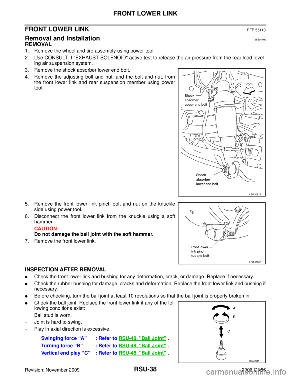
3. Remove the shock absorber lower end bolt.
4. Remove the adjusting bolt and nut, and the bolt and nut, from the front lower link and rear suspension member using power
tool.
5. Remove the front lower link pinch bolt and nut on the knuckle side using power tool.
6. Disconnect the front lower link from the knuckle using a soft hammer.
CAUTION:
Do not damage the ball joint with the soft hammer.
7. Remove the front lower link.
INSPECTION AFTER REMOVAL
�Check the front lower link and bushing for any deformation, crack, or damage. Replace if necessary.
�Check the rubber bushing for damage, cracks and deformation. Replace the front lower link and bushing if
necessary.
�Before checking, turn the ball joint at least 10 revolutions so that the ball joint is properly broken in.
�Check the ball joint. Replace the front lower link if any of the fol-
lowing conditions exist:
–Ball stud is worn.
–Joint is hard to swing.
–Play in axial direction is excessive.
LEIA0082E
LEIA0086E
Swinging force “A” : Refer to RSU-48, "Ball Joint" .
Turning force “B” : Refer to RSU-48, "
Ball Joint" .
Vertical end play “C” : Refer to RSU-48, "
Ball Joint" .
SFA858A
Page 2879 of 3383

RSU-40
REAR LOWER LINK & COIL SPRING
Revision: November 20092006 QX56
REAR LOWER LINK & COIL SPRINGPFP:551B0
Removal and Installation EES001HM
REMOVAL
1. Remove the wheel and tire assembly using power tool. Refer to WT-7, "Rotation" .
2. Use CONSULT-II "EXHAUST SOLENOID" active test to release the air pressure from the rear load level- ing air suspension system.
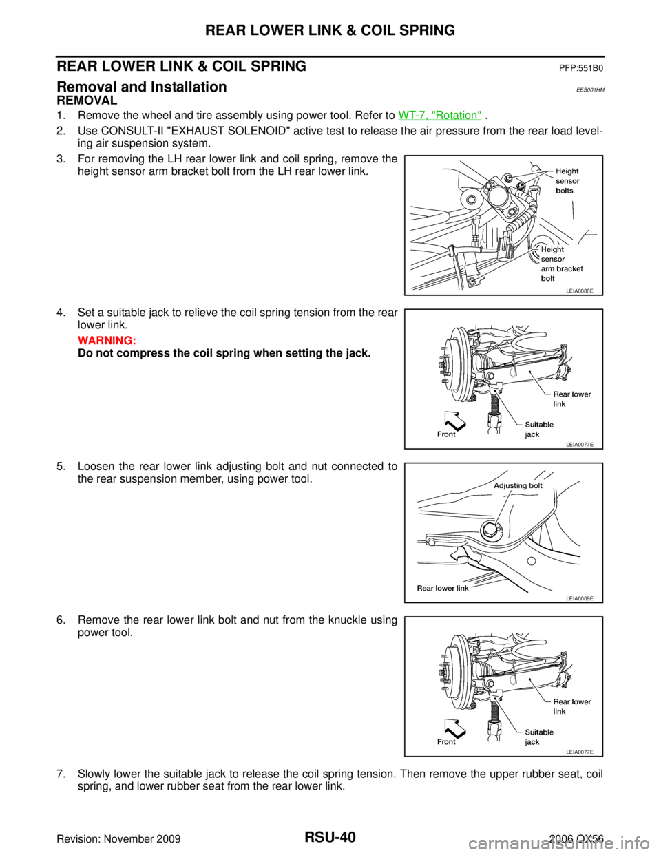
3. For removing the LH rear lower link and coil spring, remove the height sensor arm bracket bolt from the LH rear lower link.
4. Set a suitable jack to relieve the coil spring tension from the rear lower link.
WARNING:
Do not compress the coil spring when setting the jack.
5. Loosen the rear lower link adjusting bolt and nut connected to the rear suspension member, using power tool.
6. Remove the rear lower link bolt and nut from the knuckle using power tool.
7. Slowly lower the suitable jack to release the coil spring tension. Then remove the upper rubber seat, coil spring, and lower rubber seat from the rear lower link.
LEIA0080E
LEIA0077E
LEIA0009E
LEIA0077E
Page 2880 of 3383
REAR LOWER LINK & COIL SPRINGRSU-41
C
DF
G H
I
J
K L
M A
B
RSU
Revision: November 2009 2006 QX56
8. Remove the rear lower link adjusting bolt and nut from the rear
suspension member using power tool, then remove the rear
lower link.
INSPECTION AFTER REMOVAL
Check the coil spring and rubber seats for deformation, cracks, or other damage and replace if necessary.
INSTALLATION
Installation is in the reverse order of removal.
�Tighten the nuts and bolts to specification. Refer to RSU-26, "Components" .
�When installing the upper and lower rubber seats for the rear
coil springs, the arrow embossed on the rubber seats must point
out toward the wheel and tire assembly.
�After installing the rear lower link and coil spring, check the
wheel alignment and adjust if necessary. Refer to RSU-28,
"Wheel Alignment Inspection" .
LEIA0009E
LEIA0076E
Page 2881 of 3383
RSU-42
STABILIZER BAR
Revision: November 20092006 QX56
STABILIZER BARPFP:56230
Removal and Installation EES001HN
REMOVAL
1. Disconnect the stabilizer bar ends from the connecting rods
using power tool.
2. Remove the stabilizer bar clamps using power tool, and remove the stabilizer bar bushings.
3. Remove the stabilizer bar.
INSPECTION AFTER REMOVAL
�Check the stabilizer bar for any deformation, cracks, or damage and replace if necessary.
�Check the rubber bushings for deterioration, or cracks and replace if necessary.
INSTALLATION
Installation is in the reverse order of removal.
�Tighten the nuts and bolts to specification. Refer to RSU-26, "Components" .
�Install the stabilizer bar with the ball joint sockets properly
aligned.
�Install the stabilizer bar bushing and clamp so they are posi-
tioned inside of the sideslip prevention clamp on the stabilizer
bar.
LEIA0088E
LEIA0089E
SFA449BB
Page 2884 of 3383
HEIGHT SENSORRSU-45
C
DF
G H
I
J
K L
M A
B
RSU
Revision: November 2009 2006 QX56
HEIGHT SENSORPFP:53820
Removal and InstallationEES001HQ
Rear Load Leveling Air Suspension System
REMOVAL
1. Use CONSULT-II “EXHAUST SOLENOID ” active test to release the air pressure from the rear load level-
ing air suspension system.
2. Disconnect the electrical connector for the height sensor.
3. Remove the two height sensor bolts and height sensor arm bracket bolt.
4. Remove the height sensor.
LEIA0072E
1. Rear load leveling air suspension hose, RH 2. Shock absorber, RH 3. Height sensor
4. Rear load leveling air suspension hose, LH 5. Shock absorber, LH 6. Rear load leveling air suspension
compressor assembly
LEIA0080E
Page 2897 of 3383
SB-8
SEAT BELTS
Revision: November 20092006 QX56
Removal and Installation of Third Row Seat BeltEHS001N2
Third Row Outboard
REMOVAL
1. Remove the D-ring anchor bolt cover and D-ring anchor bolt.
2. Remove the lower anchor bolt cover and lower anchor bolt.
3. Remove the upper and lower luggage side finishers. Refer to EI-40, "
LUGGAGE FLOOR TRIM" .
4. Remove the seat belt retractor anchor bolt and retractor and belt assembly.
5. Remove bolt from seat belt anchor base and remove seat belt buckles.
WHIA0283E
1. D-ring mounting bracket 2. Seat belt retractor and belt assem-
bly 3. Retractor mounting bracket
4. Seat belt lower anchor 5. Lower anchor bolt cover 6. Seat belt buckles
7. D-ring anchor bolt cover 8. D-ring anchor
Page 2904 of 3383
TOP TETHER STRAP CHILD RESTRAINTSB-15
C
DE
F
G
I
J
K L
M A
B
SB
Revision: November 2009 2006 QX56
TOP TETHER STRAP CHILD RESTRAINTPFP:88000
Removal and InstallationEHS00169
1. Remove luggage room rear lower finisher. Refer to EI-40, "LUG-
GAGE FLOOR TRIM" .
2. Remove bolt and remove tether anchor from the luggage box bracket.
Installation is in the reverse order of removal.
WHIA0135E
Page 2930 of 3383
CHARGING SYSTEMSC-25
C
DE
F
G H
I
J
L
M A
B
SC
Revision: November 2009 2006 QX56
MALFUNCTION INDICATOR
The IC regulator warning function activates to illuminate “CHARGE” warning lamp, if any of the following
symptoms occur while generator is operating:
�Excessive voltage is produced.
�No voltage is produced.
Removal and InstallationEKS00B7K
REMOVAL
1. Disconnect the negative battery terminal.
2. Remove the fan shroud. Refer to CO-14, "
Removal and Installation" .
3. Remove the drive belt. Refer to EM-13, "
Removal and Installation" .
4. Remove the lower bracket, using power tools.
5. Remove the generator upper bolt, using power tools.
6. Remove/disconnect the generator harness connectors.
7. Remove the generator.
INSTALLATION
Installation is in the reverse order of removal.
�Install the generator and check the tension of the drive belt. Refer to EM-13, "DRIVE BELT TENSION" .
CAUTION:
Tighten terminal nut carefully.
WKIA1390E
Terminal nut : 10.8 N·m (1.1 kg-m, 8 ft-lb)