Page 3270 of 3383

TRANSFER ASSEMBLYTF-165
CE F
G H
I
J
K L
M A
B
TF
Revision: November 2009 2006 QX56
Bearing
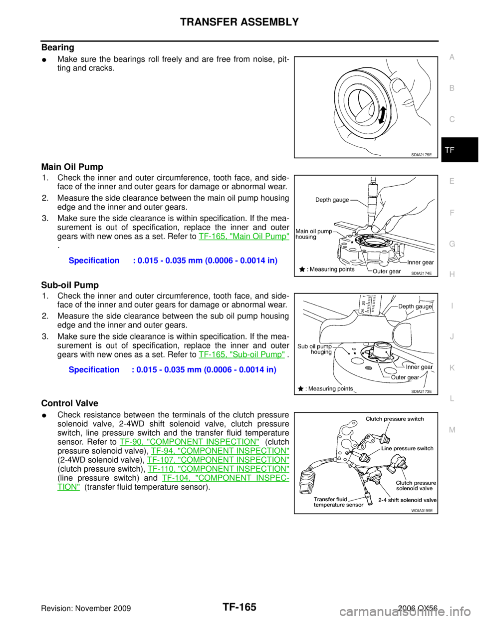
�Make sure the bearings roll freely and are free from noise, pit-
ting and cracks.
Main Oil Pump
1. Check the inner and outer circumference, tooth face, and side-
face of the inner and outer gears for damage or abnormal wear.
2. Measure the side clearance between the main oil pump housing edge and the inner and outer gears.
3. Make sure the side clearance is within specification. If the mea- surement is out of specification, replace the inner and outer
gears with new ones as a set. Refer to TF-165, "
Main Oil Pump"
.
Sub-oil Pump
1. Check the inner and outer circumference, tooth face, and side-
face of the inner and outer gears for damage or abnormal wear.
2. Measure the side clearance between the sub oil pump housing edge and the inner and outer gears.
3. Make sure the side clearance is within specification. If the mea- surement is out of specification, replace the inner and outer
gears with new ones as a set. Refer to TF-165, "
Sub-oil Pump" .
Control Valve
�Check resistance between the terminals of the clutch pressure
solenoid valve, 2-4WD shift solenoid valve, clutch pressure
switch, line pressure switch and the transfer fluid temperature
sensor. Refer to TF-90, "
COMPONENT INSPECTION" (clutch
pressure solenoid valve), TF-94, "
COMPONENT INSPECTION"
(2-4WD solenoid valve), TF-107, "COMPONENT INSPECTION"
(clutch pressure switch), TF-110, "COMPONENT INSPECTION"
(line pressure switch) and TF-104, "COMPONENT INSPEC-
TION" (transfer fluid temperature sensor).
SDIA2175E
Specification : 0.015 - 0.035 mm (0.0006 - 0.0014 in)
SDIA2174E
Specification : 0.015 - 0.035 mm (0.0006 - 0.0014 in)
SDIA2173E
WDIA0199E
Page 3271 of 3383

TF-166
TRANSFER ASSEMBLY
Revision: November 20092006 QX56
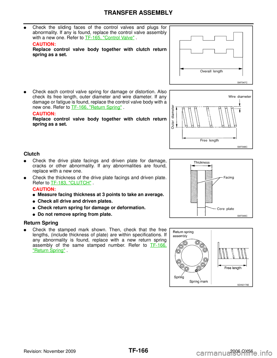
�Check the sliding faces of the control valves and plugs for
abnormality. If any is found, replace the control valve assembly
with a new one. Refer to TF-165, "
Control Valve" .
CAUTION:
Replace control valve body together with clutch return
spring as a set.
�Check each control valve spring for damage or distortion. Also
check its free length, outer diameter and wire diameter. If any
damage or fatigue is found, replace the control valve body with a
new one. Refer to TF-166, "
Return Spring" .
CAUTION:
Replace control valve body together with clutch return
spring as a set.
Clutch
�Check the drive plate facings and driven plate for damage,
cracks or other abnormality. If any abnormalities are found,
replace with a new one.
�Check the thickness of the drive plate facings and driven plate.
Refer to TF-183, "
CLUTCH" .
CAUTION:
�Measure facing thickness at 3 points to take an average.
�Check all drive and driven plates.
�Check return spring for damage or deformation.
�Do not remove spring from plate.
Return Spring
�Check the stamped mark shown. Then, check that the free
lengths, (include thickness of plate) are within specifications. If
any abnormality is found, replace with a new return spring
assembly of the same stamped number. Refer to TF-166,
"Return Spring" .
SMT947C
SMT948C
SMT949C
SDIA2176E
Page 3273 of 3383

TF-168
TRANSFER ASSEMBLY
Revision: November 20092006 QX56
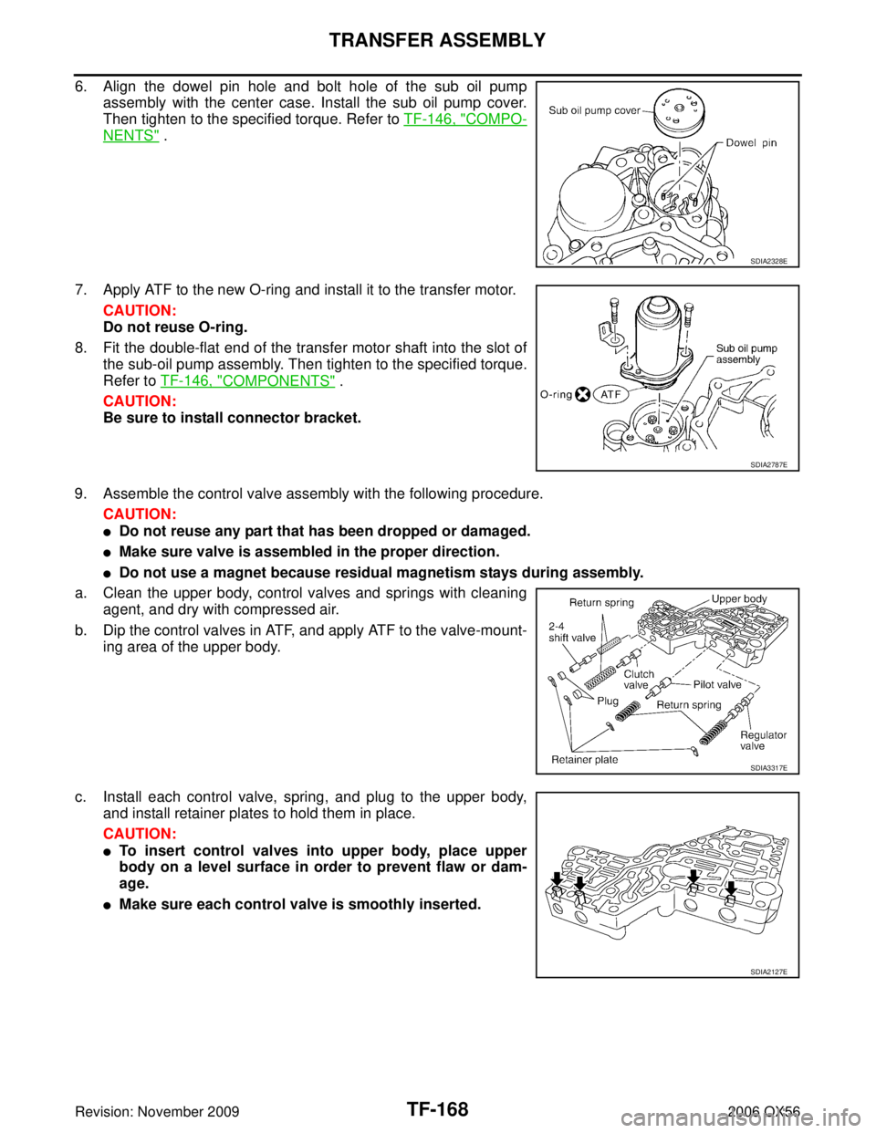
6. Align the dowel pin hole and bolt hole of the sub oil pump
assembly with the center case. Install the sub oil pump cover.
Then tighten to the specified torque. Refer to TF-146, "
COMPO-
NENTS" .
7. Apply ATF to the new O-ring and install it to the transfer motor. CAUTION:
Do not reuse O-ring.
8. Fit the double-flat end of the transfer motor shaft into the slot of the sub-oil pump assembly. Then tighten to the specified torque.
Refer to TF-146, "
COMPONENTS" .
CAUTION:
Be sure to install connector bracket.
9. Assemble the control valve assembly with the following procedure. CAUTION:
�Do not reuse any part that has been dropped or damaged.
�Make sure valve is assembled in the proper direction.
�Do not use a magnet because residual magnetism stays during assembly.
a. Clean the upper body, control valves and springs with cleaning agent, and dry with compressed air.
b. Dip the control valves in ATF, and apply ATF to the valve-mount- ing area of the upper body.
c. Install each control valve, spring, and plug to the upper body, and install retainer plates to hold them in place.
CAUTION:
�To insert control valves into upper body, place upper
body on a level surface in order to prevent flaw or dam-
age.
�Make sure each control valve is smoothly inserted.
SDIA2328E
SDIA2787E
SDIA3317E
SDIA2127E
Page 3285 of 3383

TF-180
TRANSFER ASSEMBLY
Revision: November 20092006 QX56
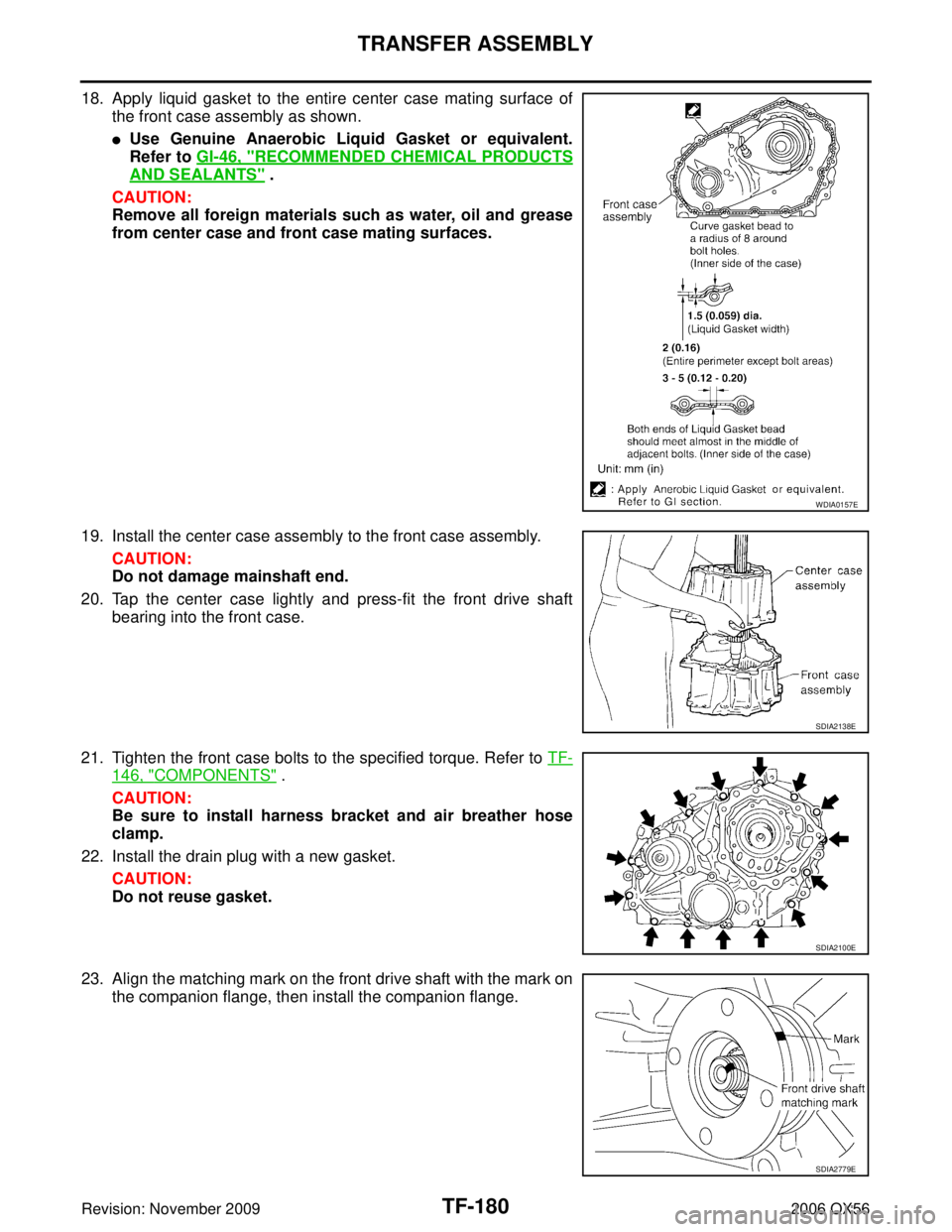
18. Apply liquid gasket to the entire center case mating surface of
the front case assembly as shown.
�Use Genuine Anaerobic Liquid Gasket or equivalent.
Refer to GI-46, "
RECOMMENDED CHEMICAL PRODUCTS
AND SEALANTS" .
CAUTION:
Remove all foreign materials such as water, oil and grease
from center case and front case mating surfaces.
19. Install the center case assembly to the front case assembly. CAUTION:
Do not damage mainshaft end.
20. Tap the center case lightly and press-fit the front drive shaft bearing into the front case.
21. Tighten the front case bolts to the specified torque. Refer to TF-
146, "COMPONENTS" .
CAUTION:
Be sure to install harness bracket and air breather hose
clamp.
22. Install the drain plug with a new gasket. CAUTION:
Do not reuse gasket.
23. Align the matching mark on the front drive shaft with the mark on the companion flange, then install the companion flange.
WDIA0157E
SDIA2138E
SDIA2100E
SDIA2779E
Page 3294 of 3383
WHEELWT-5
C
DF
G H
I
J
K L
M A
B
WT
Revision: November 2009 2006 QX56
WHEELPFP:40300
InspectionEES001HZ
1. Check tires for wear and improper inflation.
2. Check wheels for deformation, cracks and other damage. If
deformed, remove wheel and check wheel runout.
a. Remove tire from wheel and mount wheel on a tire balance machine.
b. Set dial indicator as shown. Refer to WT-38, "
Road Wheel" .
3. Check front wheel bearings for looseness.
4. Check front suspension for looseness.
SFA975B