Page 2755 of 3383
PS-22
POWER STEERING OIL PUMP
Revision: November 20092006 QX56
Disassembly and AssemblyEGS00123
INSPECTION BEFORE DISASSEMBLY
Disassemble the power steering oil pump only if the following items are found.
�Deformed or damaged pulley, bracket, connector or suction pipe.
�Oil leakage from the suction pipe or connector.
DISASSEMBLY
NOTE:
Mount the power steering oil pump in a vise as needed.
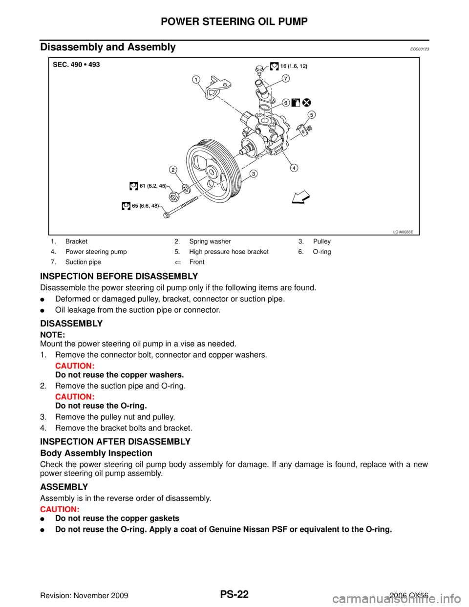
1. Remove the connector bolt, connector and copper washers.
CAUTION:
Do not reuse the copper washers.
2. Remove the suction pipe and O-ring.
CAUTION:
Do not reuse the O-ring.
3. Remove the pulley nut and pulley.
4. Remove the bracket bolts and bracket.
INSPECTION AFTER DISASSEMBLY
Body Assembly Inspection
Check the power steering oil pump body assembly for damage. If any damage is found, replace with a new
power steering oil pump assembly.
ASSEMBLY
Assembly is in the reverse order of disassembly.
CAUTION:
�Do not reuse the copper gaskets
�Do not reuse the O-ring. Apply a coat of Genuine Nissan PSF or equivalent to the O-ring.
1. Bracket 2. Spring washer 3. Pulley
4. Power steering pump 5. High pressure hose bracket 6. O-ring
7. Suction pipe ⇐Front
LGIA0038E
Page 2756 of 3383
HYDRAULIC LINEPS-23
C
DE
F
H I
J
K L
M A
B
PS
Revision: November 2009 2006 QX56
HYDRAULIC LINEPFP:49721
Removal and InstallationEGS000UM
Refer to the following illustration for hydralic line removal.
1. Reservoir tank2. Suction hose 3. High pressure hose
4. Oil cooler 5. Steering gear assembly 6. Reservoir tank bracket
7. Eye bolt
WGIA0096E
Page 2760 of 3383
SERVICE DATA AND SPECIFICATIONS (SDS)PS-27
C
DE
F
H I
J
K L
M A
B
PS
Revision: November 2009 2006 QX56
Steering GearEGS000UQ
Oil PumpEGS000UR
Steering FluidEGS000US
Steering gear modelPR26AM
Rack neutral position, dimension “L ” (rack stroke) 85.5 mm (3.36 in)
Rack sliding force At the neutral point:
Range within ±
11.5 mm
( ± 0.453 in) from the neutral
position
(in power ON) Area average value 250.1
− 308.9 N (25.5 − 31.5 kg, 56.2 − 69.5 lb)
Area minimum value 200 N (20.4 kg, 45 lb)
Allowable variation 98 N (10 kg, 22 lb) or less
STC0034D
Relief oil pressure
9.0 − 9.8 mPa (91.77 − 99.93 kg/cm2 , 1305.34 − 1421.37 psi)
Fluid capacity
Approx. 1.0 (1-1/8 US qt, 7/8 Imp qt)
Page 2769 of 3383
RAX-8
REAR DRIVE SHAFT
Revision: November 20092006 QX56
5. Separate the drive shaft from the wheel hub and bearing assembly by lightly tapping the end with a suit-
able hammer and wood block. If it is difficult to separate, use a suitable puller.
6. Remove the drive shaft. CAUTION:
When removing the drive shaft, do not bend at an excessive angle to the drive shaft joint. Do not
excessively extend the slide joint.
INSPECTION AFTER REMOVAL
�Move the joint up and down, left and right, and in the axial direc-
tion. Check for any rough movement or significant looseness.
�Check the boot for cracks or other damage, and for any grease
leakage.
�If necessary, disassemble the drive shaft, and repair as neces-
sary.
INSTALLATION
Installation is in the reverse order of removal.
�Do not reuse the drive shaft inside flange bolts, discard after removal and use new bolts for installation.
�Do not reuse the cotter pin, discard after removal and use a new cotter pin for installation.
Disassembly and AssemblyEDS001XQ
DISASSEMBLY
Final Drive Side
1. Mount the drive shaft in a vise.CAUTION:
When mounting the drive shaft in a vise, use copper or aluminum plates between the vise and the
drive shaft.
2. Remove the boot bands.
RAA0030D
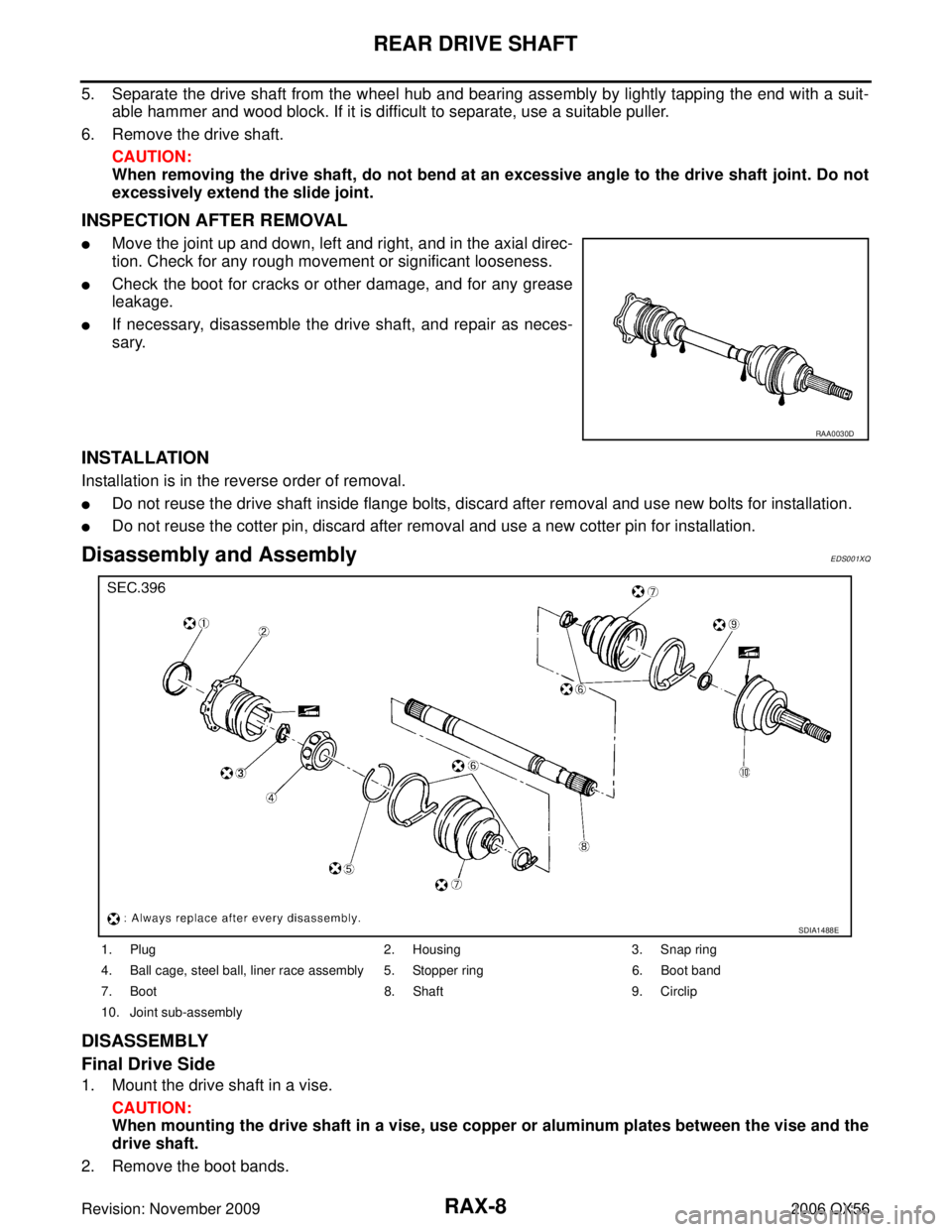
1. Plug 2. Housing3. Snap ring
4. Ball cage, steel ball, liner race assembly 5. Stopper ring 6. Boot band
7. Boot 8. Shaft9. Circlip
10. Joint sub-assembly
SDIA1488E
Page 2770 of 3383
REAR DRIVE SHAFTRAX-9
CE F
G H
I
J
K L
M A
B
RAX
Revision: November 2009 2006 QX56
3. If the plug needs to be removed, move the boot to the wheel side, then drive the plug out using a suitable
plastic hammer.
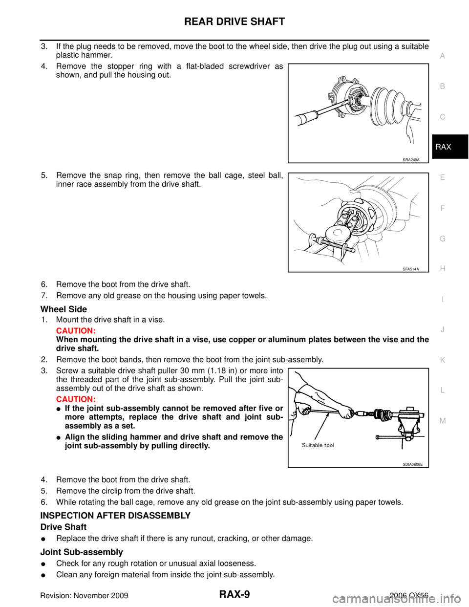
4. Remove the stopper ring with a flat-bladed screwdriver as shown, and pull the housing out.
5. Remove the snap ring, then remove the ball cage, steel ball, inner race assembly from the drive shaft.
6. Remove the boot from the drive shaft.
7. Remove any old grease on the housing using paper towels.
Wheel Side
1. Mount the drive shaft in a vise. CAUTION:
When mounting the drive shaft in a vise, use copper or aluminum plates between the vise and the
drive shaft.
2. Remove the boot bands, then remove the boot from the joint sub-assembly.
3. Screw a suitable drive shaft puller 30 mm (1.18 in) or more into the threaded part of the joint sub-assembly. Pull the joint sub-
assembly out of the drive shaft as shown.
CAUTION:
�If the joint sub-assembly cannot be removed after five or
more attempts, replace the drive shaft and joint sub-
assembly as a set.
�Align the sliding hammer and drive shaft and remove the
joint sub-assembly by pulling directly.
4. Remove the boot from the drive shaft.
5. Remove the circlip from the drive shaft.
6. While rotating the ball cage, remove any old grease on the joint sub-assembly using paper towels.
INSPECTION AFTER DISASSEMBLY
Drive Shaft
�Replace the drive shaft if there is any runout, cracking, or other damage.
Joint Sub-assembly
�Check for any rough rotation or unusual axial looseness.
�Clean any foreign material from inside the joint sub-assembly.
SRA249A
SFA514A
SDIA0606E
Page 2771 of 3383
RAX-10
REAR DRIVE SHAFT
Revision: November 20092006 QX56
�Check for any compression scars, cracks, or fractures.
CAUTION:
If any defective conditions are found in the joint sub-assembly components, replace the entire
joint sub-assembly.
Sliding Joint Side (Housing)
�Check for any compression scars, cracks, fractures, or unusual wear on the ball rolling surface.
�Check for any damage to the drive shaft screws.
�Check for any deformation of the boot installation components.
Ball Cage
�Check the sliding surface for any compression scars, cracks, or fractures.
Steel Ball
�Check for any compression scars, cracks, fractures, or unusual wear.
Inner Race
�Check the ball sliding surface for any compression scars, cracks, or fractures.
�Check for any damage to the serrated part.
CAUTION:
If any defective conditions are found, install a new housing, ball cage, steel ball, and inner race as
a set.
ASSEMBLY
Final Drive Side
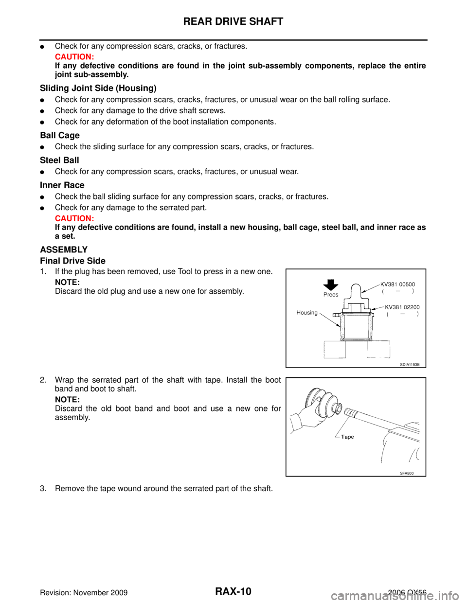
1. If the plug has been removed, use Tool to press in a new one.
NOTE:
Discard the old plug and use a new one for assembly.
2. Wrap the serrated part of the shaft with tape. Install the boot band and boot to shaft.
NOTE:
Discard the old boot band and boot and use a new one for
assembly.
3. Remove the tape wound around the serrated part of the shaft.
SDIA1153E
SFA800
Page 2782 of 3383
SQUEAK AND RATTLE TROUBLE DIAGNOSESRF-7
C
DE
F
G H
J
K L
M A
B
RF
Revision: November 2009 2006 QX56
TRUNK
Trunk noises are often caused by a loose jack or loose items put into the trunk by the owner.
In addition look for:
1. Trunk lid bumpers out of adjustment
2. Trunk lid striker out of adjustment
3. The trunk lid torsion bars knocking together
4. A loose license plate or bracket
Most of these incidents can be repaired by adjusting, securing or insulating the item(s) or component(s) caus-
ing the noise.
SUNROOF/HEADLINING
Noises in the sunroof/headlining area can often be traced to one of the following:
1. Sunroof lid, rail, linkage or seals making a rattle or light knocking noise
2. Sun visor shaft shaking in the holder
3. Front or rear windshield touching headliner and squeaking
Again, pressing on the components to stop the noise while duplicating the conditions can isolate most of these
incidents. Repairs usually consist of insulating with felt cloth tape.
OVERHEAD CONSOLE (FRONT AND REAR)
Overhead console noises are often caused by the console panel clips not being engaged correctly. Most of
these incidents are repaired by pushing up on the console at the clip locations until the clips engage.
In addition look for:
1. Loose harness or harness connectors.
2. Front console map/reading lamp lens loose.
3. Loose screws at console attachment points.
SEATS
When isolating seat noise it's important to note the position the seat is in and the load placed on the seat when
the noise is present. These conditions should be duplicated when verifying and isolating the cause of the
noise.
Cause of seat noise include:
1. Headrest rods and holder
2. A squeak between the seat pad cushion and frame
3. The rear seatback lock and bracket
These noises can be isolated by moving or pressing on the suspected components while duplicating the con-
ditions under which the noise occurs. Most of these incidents can be repaired by repositioning the component
or applying urethane tape to the contact area.
UNDERHOOD
Some interior noise may be caused by components under the hood or on the engine wall. The noise is then
transmitted into the passenger compartment.
Causes of transmitted underhood noise include:
1. Any component installed to the engine wall
2. Components that pass through the engine wall
3. Engine wall mounts and connectors
4. Loose radiator installation pins
5. Hood bumpers out of adjustment
6. Hood striker out of adjustment
These noises can be difficult to isolate since they cannot be reached from the interior of the vehicle. The best
method is to secure, move or insulate one component at a time and test drive the vehicle. Also, engine RPM
or load can be changed to isolate the noise. Repairs can usually be made by moving, adjusting, securing, or
insulating the component causing the noise.
Page 2799 of 3383
RF-24
SUNROOF
Revision: November 20092006 QX56
HEIGHT DIFFERENCE ADJUSTMENT
If an excessive height difference between glass lid assembly and roof panel is found, adjust in the following
manner:
1. Remove headlining. Refer to EI-38, "
HEADLINING" .
2. Loosen sunroof frame assembly nuts and sunroof bracket bolts.
3. Add shims until gap is within specification "A-A". NOTE:
Temporarily snug nuts and bolts to prevent movement between each adjustment.
4. Tilt glass lid assembly up and down several times to check that it moves and seals properly.
5. Tighten sunroof frame assembly nuts and sunroof bracket bolts. NOTE:
First tighten left front then right rear sunroof frame assembly to prevent uneven torque while tightening
remaining sunroof bracket bolts.
6. Install headlining. Refer to EI-38, "
HEADLINING" .
Removal and InstallationEIS007XH
�After any adjustment, check sunroof operation and glass lid assembly alignment.
�Handle glass lid assembly with care so not to cause damage.
�For easier installation, mark each point before removal.
CAUTION:
�Always work with a helper.
�Before removal, fully close the glass lid assembly. Then, after removal, do not move the sunroof
motor assembly.