Page 1525 of 3383
EC-314Revision: November 2009
DTC P0181 FTT SENSOR
2006 QX56
Component InspectionUBS00H39
FUEL TANK TEMPERATURE SENSOR
1. Remove fuel level sensor unit.
2. Check resistance between “fuel level sensor unit and fuel pump ”
terminals 3 and 4 by heating with hot water or heat gun as
shown in the figure.
Removal and InstallationUBS00H3A
FUEL TANK TEMPERATURE SENSOR
Refer to FL-6, "FUEL LEVEL SENSOR UNIT, FUEL FILTER AND FUEL PUMP ASSEMBLY" .
Temperature °C (°F) Resistance kΩ
20 (68) 2.3 - 2.7
50 (122) 0.79 - 0.90
SEF476YA
Page 1530 of 3383
DTC P0182, P0183 FTT SENSOREC-319
C
DE
F
G H
I
J
K L
M A
EC
Revision: November 2009 2006 QX56
Component InspectionUBS00H3G
FUEL TANK TEMPERATURE SENSOR
1. Remove fuel level sensor unit.
2. Check resistance between “fuel level sensor unit and fuel pump”
terminals 3 and 4 by heating with hot water or heat gun as
shown in the figure.
Removal and InstallationUBS00H3H
FUEL TANK TEMPERATURE SENSOR
Refer to FL-6, "FUEL LEVEL SENSOR UNIT, FUEL FILTER AND FUEL PUMP ASSEMBLY" .
Temperature °C ( °F) Resistance kΩ
20 (68) 2.3 - 2.7
50 (122) 0.79 - 0.90
SEF476YA
Page 1633 of 3383
EC-422Revision: November 2009
DTC P0455 EVAP CONTROL SYSTEM
2006 QX56
5. CHECK EVAP PURGE LINE
Check EVAP purge line (pipe, rubber tube, fuel tank and EVAP canister) for cracks, improper connection or
disconnection.
Refer to EC-33, "
EVAPORATIVE EMISSION LINE DRAWING" .
OK or NG
OK >> GO TO 6.
NG >> Repair or reconnect the hose.
6. CLEAN EVAP PURGE LINE
Clean EVAP purge line (pipe and rubber tube) using air blower.
>> GO TO 7.
7. CHECK EVAP CANISTER VENT CONTROL VALVE
Check the following.
�EVAP canister vent control valve is installed properly.
Refer to EC-36, "
Removal and Installation" .
�EVAP canister vent control valve.
Refer to EC-393, "
Component Inspection" .
OK or NG
OK >> GO TO 8.
NG >> Repair or replace EVAP canister vent control valve and O-ring.
8. INSTALL THE PRESSURE PUMP
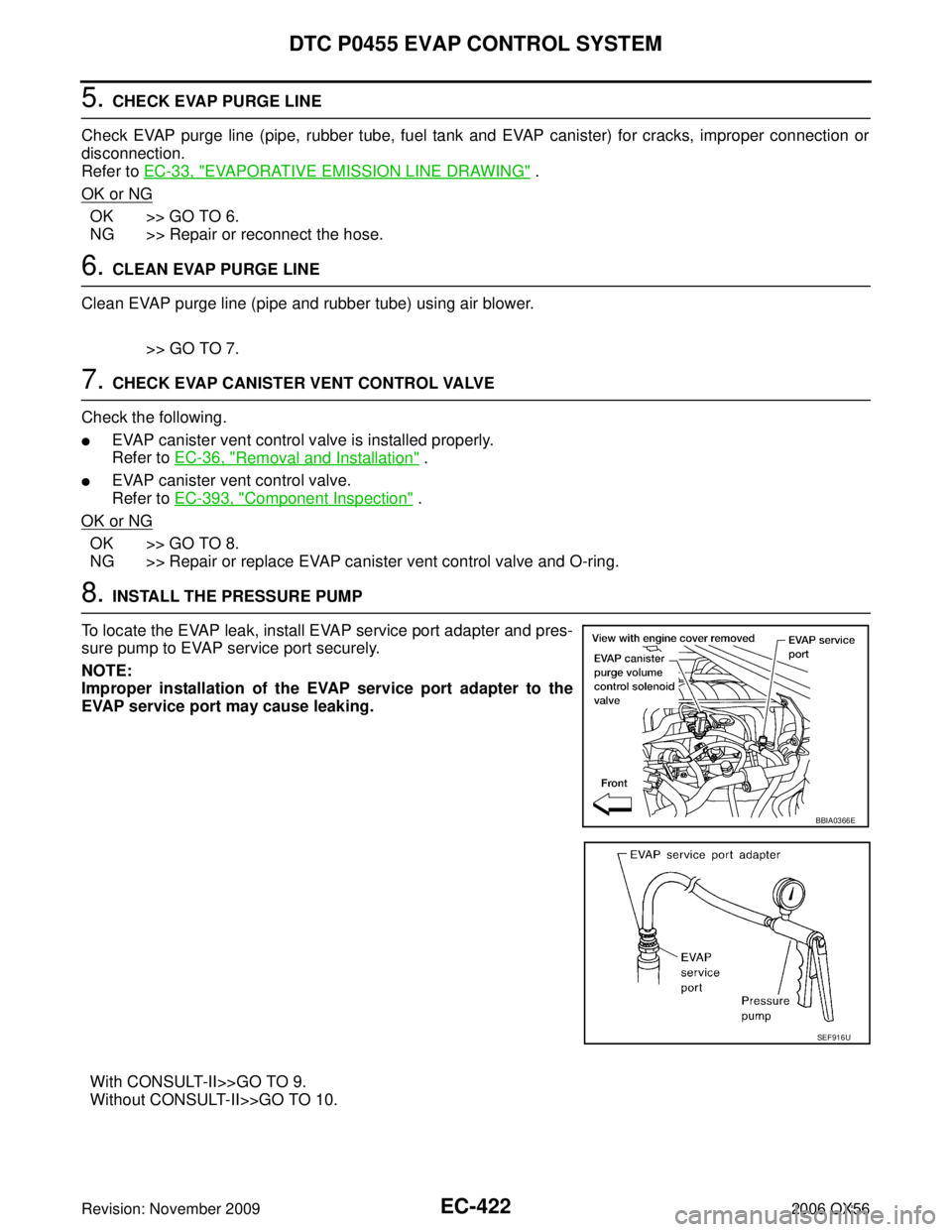
To locate the EVAP leak, install EVAP service port adapter and pres-
sure pump to EVAP service port securely.
NOTE:
Improper installation of the EVAP service port adapter to the
EVAP service port may cause leaking.
With CONSULT-II>>GO TO 9.
Without CONSULT-II>>GO TO 10.
BBIA0366E
SEF916U
Page 1650 of 3383
DTC P0461 FUEL LEVEL SENSOREC-439
C
DE
F
G H
I
J
K L
M A
EC
Revision: November 2009 2006 QX56
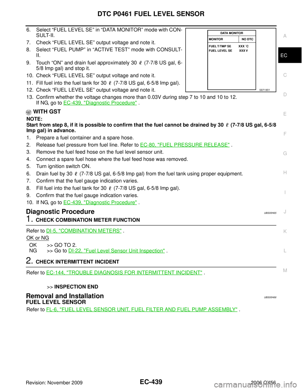
6. Select “FUEL LEVEL SE ” in “DATA MONITOR” mode with CON-
SULT-II.
7. Check “FUEL LEVEL SE ” output voltage and note it.
8. Select “FUEL PUMP ” in “ACTIVE TEST ” mode with CONSULT-
II.
9. Touch “ON” and drain fuel approximately 30 (7-7/8 US gal, 6-
5/8 Imp gal) and stop it.
10. Check “FUEL LEVEL SE ” output voltage and note it.
11. Fill fuel into the fuel tank for 30 (7-7/8 US gal, 6-5/8 Imp gal).
12. Check “FUEL LEVEL SE ” output voltage and note it.
13. Confirm whether the voltage changes more than 0.03V during step 7 to 10 and 10 to 12. If NG, go to EC-439, "
Diagnostic Procedure" .
WITH GST
NOTE:
Start from step 8, if it is possible to confirm that the fuel cannot be drained by 30 (7-7/8 US gal, 6-5/8
Imp gal) in advance.
1. Prepare a fuel container and a spare hose.
2. Release fuel pressure from fuel line. Refer to EC-80, "
FUEL PRESSURE RELEASE" .
3. Remove the fuel feed hose on the fuel level sensor unit.
4. Connect a spare fuel hose where the fuel feed hose was removed.
5. Turn ignition switch ON.
6. Drain fuel by 30 (7-7/8 US gal, 6-5/8 Imp gal) from the fuel tank using proper equipment.
7. Confirm that the fuel gauge indication varies.
8. Fill fuel into the fuel tank for 30 (7-7/8 US gal, 6-5/8 Imp gal).
9. Confirm that the fuel gauge indication varies.
10. If NG, go to EC-439, "
Diagnostic Procedure" .
Diagnostic ProcedureUBS00H65
1. CHECK COMBINATION METER FUNCTION
Refer to DI-5, "
COMBINATION METERS" .
OK or NG
OK >> GO TO 2.
NG >> Go to DI-22, "
Fuel Level Sensor Unit Inspection" .
2. CHECK INTERMITTENT INCIDENT
Refer to EC-144, "
TROUBLE DIAGNOSIS FOR INTERMITTENT INCIDENT" .
>> INSPECTION END
Removal and InstallationUBS00H66
FUEL LEVEL SENSOR
Refer to FL-6, "FUEL LEVEL SENSOR UNIT, FUEL FILTER AND FUEL PUMP ASSEMBLY" .
SEF195Y
Page 1966 of 3383
ENGINE ASSEMBLYEM-75
C
DE
F
G H
I
J
K L
M A
EM
Revision: November 2009 2006 QX56
4. Remove the engine hood. Refer to BL-13, "Removal and Installation of Hood Assembly" .
5. Remove the cowl extension. Refer to EI-18, "
Removal and Installation" .
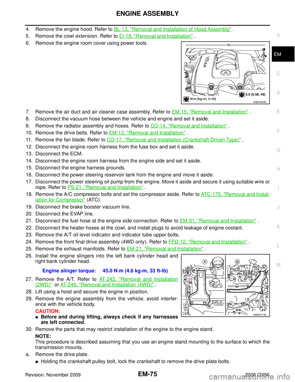
6. Remove the engine room cover using power tools.
7. Remove the air duct and air cleaner case assembly. Refer to EM-15, "
Removal and Installation" .
8. Disconnect the vacuum hose between the vehicle and engine and set it aside.
9. Remove the radiator assembly and hoses. Refer to CO-14, "
Removal and Installation" .
10. Remove the drive belts. Refer to EM-13, "
Removal and Installation" .
11. Remove the fan blade. Refer to CO-17, "
Removal and Installation (Crankshaft Driven Type)" .
12. Disconnect the engine room harness from the fuse box and set it aside.
13. Disconnect the ECM.
14. Disconnect the engine room harness from the engine side and set it aside.
15. Disconnect the engine harness grounds.
16. Disconnect the power steering reservoir tank from the engine and move it aside.
17. Disconnect the power steering oil pump from the engine. Move it aside and secure it using suitable wire or rope. Refer to PS-21, "
Removal and Installation" .
18. Remove the A/C compressor bolts and set the compressor aside. Refer to ATC-175, "
Removal and Instal-
lation for Compressor" (ATC).
19. Disconnect the brake booster vacuum line.
20. Disconnect the EVAP line.
21. Disconnect the fuel hose at the engine side connection. Refer to EM-31, "
Removal and Installation" .
22. Disconnect the heater hoses at the cowl, and install plugs to avoid leakage of engine coolant.
23. Remove the A/T oil level indicator and indicator tube upper bolts.
24. Remove the front final drive assembly (4WD only). Refer to FFD-12, "
Removal and Installation" .
25. Remove the exhaust manifolds. Refer to EM-21, "
Removal and Installation" .
26. Install the engine slingers into the left bank cylinder head and right bank cylinder head.
27. Remove the A/T. Refer to AT- 2 4 3 , "
Removal and Installation
(2WD)" or AT- 2 4 6 , "Removal and Installation (4WD)" .
28. Lift using a hoist and secure the engine in position.
29. Remove the engine assembly from the vehicle, avoid interfer- ence with the vehicle body.
CAUTION:
�Before and during lifting, always check if any harnesses
are left connected.
30. Remove the parts that may restrict installation of the engine to the engine stand.
NOTE:
This procedure is described assuming that you use an engine stand mounting to the surface to which the
transmission mounts.
a. Remove the drive plate.
�Holding the crankshaft pulley bolt, lock the crankshaft to remove the drive plate bolts.
WBIA0464E
Engine slinger torque: 45.0 N·m (4.6 kg-m, 33 ft-lb)
WBIA0715E
Page 2056 of 3383
FL-1
FUEL SYSTEM
B ENGINE
CONTENTS
C
DE
F
G H
I
J
K L
M
SECTION
A
FL
Revision: November 2009 2006 QX56
PRECAUTIONS .....................................................
..... 2
Precautions for Supplemental Restraint System
(SRS) “AIR BAG” and “SEAT BELT PRE-TEN-
SIONER” ............................................................. ..... 2
PREPARATION ...................................................... ..... 3
Special Service Tools .......................................... ..... 3
Commercial Service Tool .................................... ..... 3
FUEL SYSTEM ........................................................... 4 Checking Fuel Lines ................................................. 4
General Precautions ........................................... ..... 4
FUEL LEVEL SENSOR UNIT, FUEL FILTER AND FUEL PUMP ASSEMBLY ......................................
..... 6
Removal and Installation ..................................... ..... 6
REMOVAL ........................................................ ..... 6
INSTALLATION ................................................ ..... 9
INSPECTION AFTER INSTALLATION ............. ..... 9
FUEL TANK ........................................................... ... 10
Removal and Installation ..................................... ... 10
REMOVAL ........................................................ ... 11
INSTALLATION ................................................ ... 14
INSPECTION AFTER INSTALLATION ............. ... 14
SERVICE DATA AND SPECIFICATIONS (SDS) ... ... 15
Standard and Limit ............................................... ... 15
Page 2061 of 3383
FL-6Revision: November 2009
FUEL LEVEL SENSOR UNIT, FUEL FILTER AND FUEL PUMP ASSEMBLY
2006 QX56
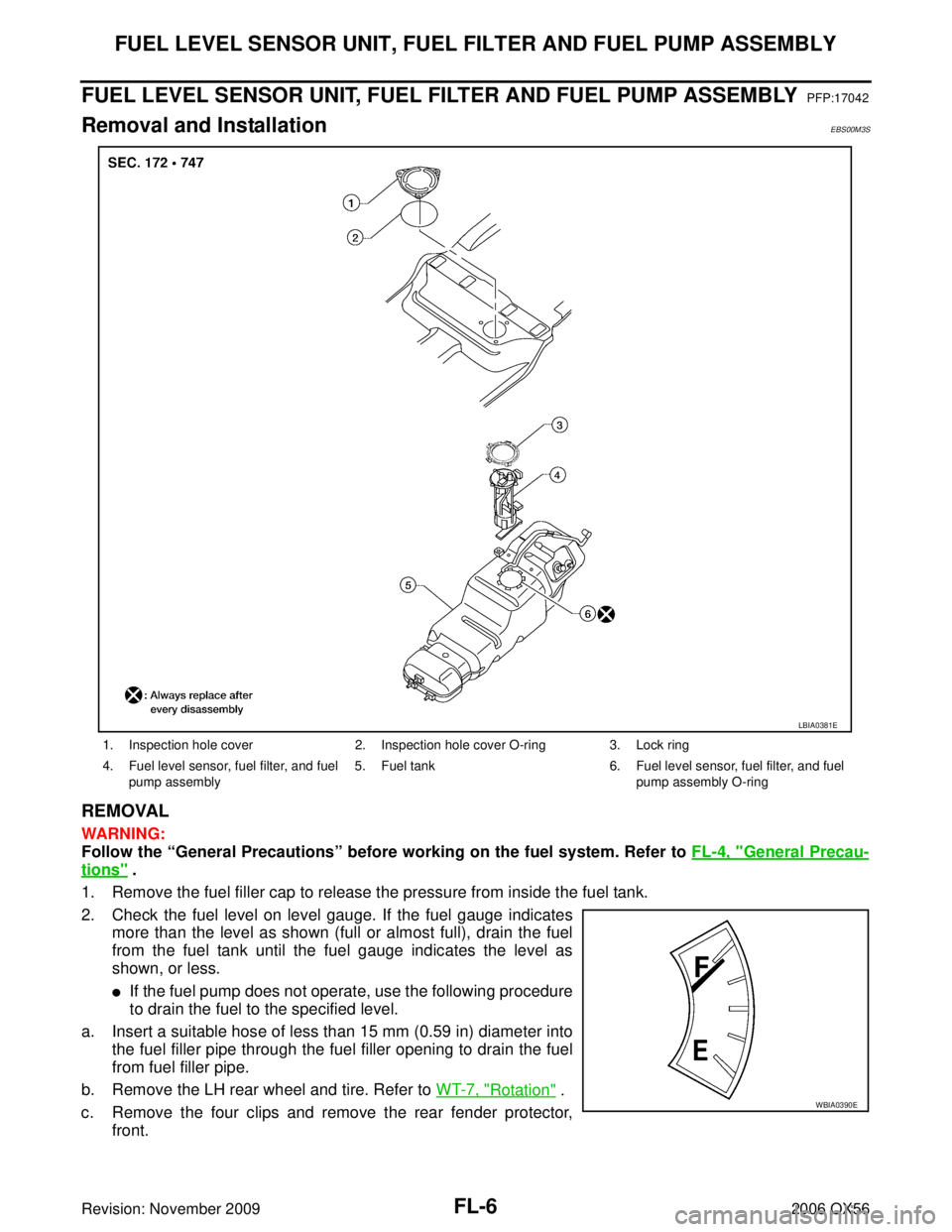
FUEL LEVEL SENSOR UNIT, FUEL FILTER AND FUEL PUMP ASSEMBLYPFP:17042
Removal and InstallationEBS00M3S
REMOVAL
WARNING:
Follow the “General Precautions” before working on the fuel system. Refer to FL-4, "
General Precau-
tions" .
1. Remove the fuel filler cap to release the pressure from inside the fuel tank.
2. Check the fuel level on level gauge. If the fuel gauge indicates more than the level as shown (full or almost full), drain the fuel
from the fuel tank until the fuel gauge indicates the level as
shown, or less.
�If the fuel pump does not operate, use the following procedure
to drain the fuel to the specified level.
a. Insert a suitable hose of less than 15 mm (0.59 in) diameter into the fuel filler pipe through the fuel filler opening to drain the fuel
from fuel filler pipe.
b. Remove the LH rear wheel and tire. Refer to WT-7, "
Rotation" .
c. Remove the four clips and remove the rear fender protector, front.
1. Inspection hole cover 2. Inspection hole cover O-ring 3. Lock ring
4. Fuel level sensor, fuel filter, and fuel pump assembly 5. Fuel tank
6. Fuel level sensor, fuel filter, and fuel
pump assembly O-ring
LBIA0381E
WBIA0390E
Page 2065 of 3383
FL-10Revision: November 2009
FUEL TANK
2006 QX56
FUEL TANKPFP:17202
Removal and InstallationEBS00M3T
1. Inspection hole cover2. Inspection hole cover O-ring 3. Lock ring
4. Fuel level sensor, fuel filter, and fuel pump assembly 5. Fuel tank
6. Fuel tank protector
7. Fuel tank protector clips 8. Fuel tank straps 9. Fuel level sensor, fuel filter, and fuel
pump assembly O-ring
WBIA0443E