Page 1496 of 3383

DTC P0139, P0159 HO2S2EC-285
C
DE
F
G H
I
J
K L
M A
EC
Revision: November 2009 2006 QX56
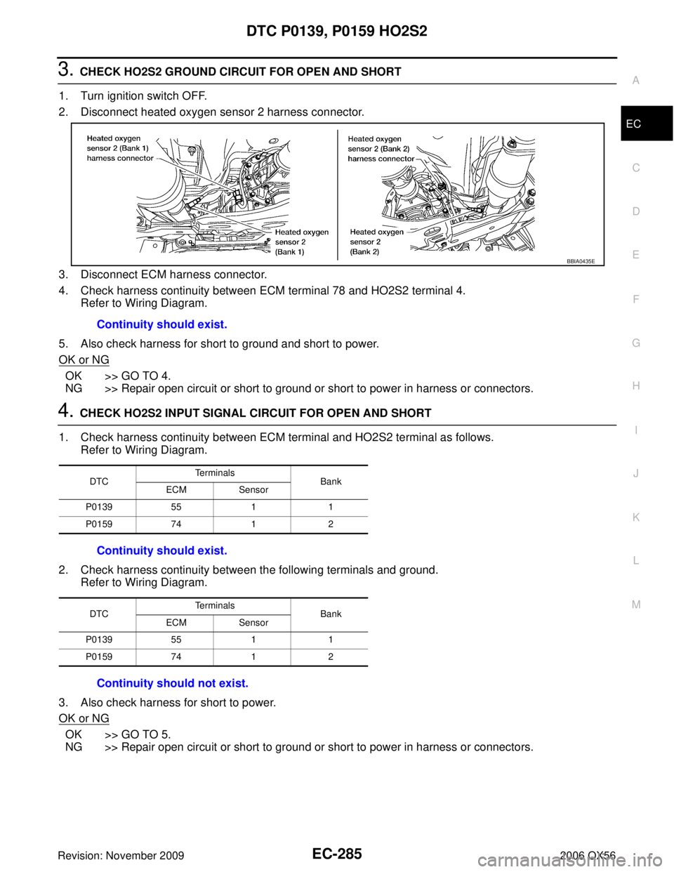
3. CHECK HO2S2 GROUND CIRCUIT FOR OPEN AND SHORT
1. Turn ignition switch OFF.
2. Disconnect heated oxygen sensor 2 harness connector.
3. Disconnect ECM harness connector.
4. Check harness continuity between ECM terminal 78 and HO2S2 terminal 4. Refer to Wiring Diagram.
5. Also check harness for short to ground and short to power.
OK or NG
OK >> GO TO 4.
NG >> Repair open circuit or short to ground or short to power in harness or connectors.
4. CHECK HO2S2 INPUT SIGNAL CIRCUIT FOR OPEN AND SHORT
1. Check harness continuity between ECM terminal and HO2S2 terminal as follows. Refer to Wiring Diagram.
2. Check harness continuity between the following terminals and ground. Refer to Wiring Diagram.
3. Also check harness for short to power.
OK or NG
OK >> GO TO 5.
NG >> Repair open circuit or short to ground or short to power in harness or connectors. Continuity should exist.
BBIA0435E
DTC
Te r m i n a l s
Bank
ECM Sensor
P0139 5511
P0159 7412
Continuity should exist.
DTC Te r m i n a l s
Bank
ECM Sensor
P0139 5511
P0159 7412
Continuity should not exist.
Page 1501 of 3383
EC-290Revision: November 2009
DTC P0171, P0174 FUEL INJECTION SYSTEM FUNCTION
2006 QX56
Wiring DiagramUBS00L0N
BANK 1
BBWA2090E
Page 1506 of 3383
DTC P0171, P0174 FUEL INJECTION SYSTEM FUNCTIONEC-295
C
DE
F
G H
I
J
K L
M A
EC
Revision: November 2009 2006 QX56
3. CHECK A/F SENSOR 1 INPUT SIGNAL CIRCUIT
1. Turn ignition switch OFF.
2. Disconnect corresponding A/F sensor 1 harness connector.
3. Disconnect ECM harness connector.
4. Check harness continuity between the following terminals. Refer to Wiring Diagram.
5. Check harness continuity between the following terminals and ground. Refer to Wiring Diagram.
6. Also check harness for short to power.
OK or NG
OK >> GO TO 4.
NG >> Repair open circuit or short to ground or short to power in harness or connectors.
A/F sensor 1 terminal ECM terminal
Bank 1 11
6
27 5
53 5
65 6
Bank 2 17
6
27 7
55 7
65 8
Continuity should exist.
Bank 1 Bank 2
A/F sensor 1 terminal ECM terminal A/F sensor 1 terminal ECM terminal 11 617 6
27 527 7
53 555 7
65 665 8
Continuity should not exist.
BBIA0376E
Page 1512 of 3383
DTC P0172, P0175 FUEL INJECTION SYSTEM FUNCTIONEC-301
C
DE
F
G H
I
J
K L
M A
EC
Revision: November 2009 2006 QX56
Wiring DiagramUBS00L0R
BANK 1
BBWA2090E
Page 1517 of 3383
EC-306Revision: November 2009
DTC P0172, P0175 FUEL INJECTION SYSTEM FUNCTION
2006 QX56
3. CHECK A/F SENSOR 1 INPUT SIGNAL CIRCUIT
1. Turn ignition switch OFF.
2. Disconnect corresponding A/F sensor 1 harness connector.
3. Disconnect ECM harness connector.
4. Check harness continuity between the following terminals. Refer to Wiring Diagram.
5. Check harness continuity between the following terminals and ground. Refer to Wiring Diagram.
6. Also check harness for short to power.
OK or NG
OK >> GO TO 4.
NG >> Repair open circuit or short to ground or short to power in harness or connectors.
A/F sensor 1 terminal ECM terminal
Bank 1 11
6
27 5
53 5
65 6
Bank 2 17
6
27 7
55 7
65 8
Continuity should exist.
Bank 1 Bank 2
A/F sensor 1 terminal ECM terminal A/F sensor 1 terminal ECM terminal 11 617 6
27 527 7
53 555 7
65 665 8
Continuity should not exist.
BBIA0376E
Page 1522 of 3383
DTC P0181 FTT SENSOREC-311
C
DE
F
G H
I
J
K L
M A
EC
Revision: November 2009 2006 QX56
Wiring DiagramUBS00H37
BBWA2092E
Page 1524 of 3383

DTC P0181 FTT SENSOREC-313
C
DE
F
G H
I
J
K L
M A
EC
Revision: November 2009 2006 QX56
4. DETECT MALFUNCTIONING PART
Check the following.
�Harness connectors C1, E41
�Harness for open or short between ECM and “fuel level sensor unit and fuel pump”
>> Repair harness or connector.
5. CHECK FUEL TANK TEMPERATURE SENSOR GROUND CIRCUIT FOR OPEN AND SHORT
1. Turn ignition switch OFF.
2. Disconnect combination meter harness connector.
3. Check harness continuity between “fuel level sensor unit and fuel pump” terminal 3 and combination
meter terminal 16. Refer to Wiring Diagram.
4. Also check harness for short to ground and short to power.
OK or NG
OK >> GO TO 7.
NG >> GO TO 6.
6. DETECT MALFUNCTIONING PART
Check the following.
�Harness connectors C1, E41
�Harness connectors E152, M31
�Harness for open or short between “fuel level sensor unit and fuel pump ” and combination meter
>> Repair open circuit or short to ground or short to power in harness or connector.
7. CHECK FUEL TANK TEMPERATURE SENSOR
Refer to EC-314, "
Component Inspection" .
OK or NG
OK >> GO TO 8.
NG >> Replace “fuel level sensor unit and fuel pump ”.
8. CHECK INTERMITTENT INCIDENT
Refer to EC-144, "
TROUBLE DIAGNOSIS FOR INTERMITTENT INCIDENT" .
>> INSPECTION END
Continuity should exist.
Page 1527 of 3383
EC-316Revision: November 2009
DTC P0182, P0183 FTT SENSOR
2006 QX56
Wiring DiagramUBS00H3E
BBWA2092E