Page 1941 of 3383
EM-50Revision: November 2009
CAMSHAFT
2006 QX56
INSPECTION AFTER REMOVAL
Camshaft Runout
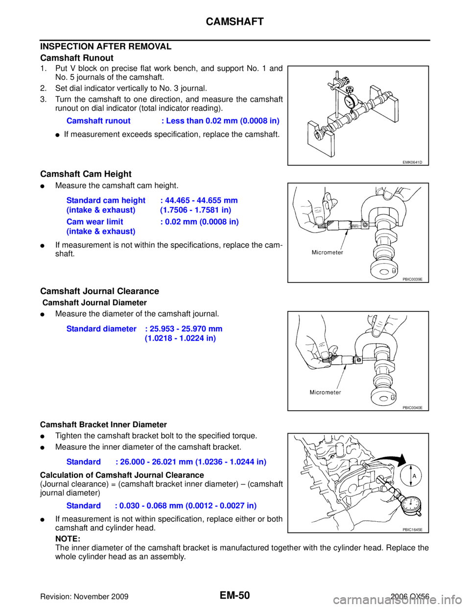
1. Put V block on precise flat work bench, and support No. 1 andNo. 5 journals of the camshaft.
2. Set dial indicator vertically to No. 3 journal.
3. Turn the camshaft to one direction, and measure the camshaft runout on dial indicator (total indicator reading).
�If measurement exceeds specification, replace the camshaft.
Camshaft Cam Height
�Measure the camshaft cam height.
�If measurement is not within the specifications, replace the cam-
shaft.
Camshaft Journal Clearance
Camshaft Journal Diameter
�Measure the diameter of the camshaft journal.
Camshaft Bracket Inner Diameter
�Tighten the camshaft bracket bolt to the specified torque.
�Measure the inner diameter of the camshaft bracket.
Calculation of Camshaft Journal Clearance
(Journal clearance) = (camshaft bracket inner diameter) – (camshaft
journal diameter)
�If measurement is not within specification, replace either or both
camshaft and cylinder head.
NOTE:
The inner diameter of the camshaft bracket is manufactured together with the cylinder head. Replace the
whole cylinder head as an assembly. Camshaft runout : Less than 0.02 mm (0.0008 in)
EMK0641D
Standard cam height
(intake & exhaust)
: 44.465 - 44.655 mm
(1.7506 - 1.7581 in)
Cam wear limit
(intake & exhaust) : 0.02 mm (0.0008 in)
PBIC0039E
Standard diameter : 25.953 - 25.970 mm
(1.0218 - 1.0224 in)
PBIC0040E
Standard : 26.000 - 26.021 mm (1.0236 - 1.0244 in)
Standard : 0.030 - 0.068 mm (0.0012 - 0.0027 in)
PBIC1645E
Page 1942 of 3383

CAMSHAFTEM-51
C
DE
F
G H
I
J
K L
M A
EM
Revision: November 2009 2006 QX56
Camshaft End Play
�Install dial gauge in the thrust direction on the front end of the
camshaft. Measure the end play when the camshaft is moved
forward/backward (in direction to axis).
�If measurement is out of the specified range, replace the cam-
shaft and measure again.
�If measurement is still out of the specified range, replace the cyl-
inder head.
�Measure the following parts if end play is outside the specified
value.
–Dimension ″A″ for camshaft No. 1 journal
–Dimension ″B″ for cylinder head No. 1 journal
�If measurements are not within specification, replace the cam-
shaft and/or cylinder head.
Camshaft Sprocket Runout
1. Install the camshaft in the cylinder head.
2. Install the camshaft sprocket to the camshaft.
3. Measure the camshaft sprocket runout.
�If measurement exceeds the specification, replace the cam-
shaft sprocket.
Valve Lifter
Check if the surface of the valve lifter has any wear or cracks.
�If any damage is found, replace the valve lifter.
�Select the thickness of the head so that the valve clearance is
within the standard when replacing. Refer to EM-55, "
Va l v e
Clearance" .
Standard : 0.115 - 0.188 mm (0.0045 - 0.0074 in)
PBIC0042E
Standard : 30.500 - 30.548 mm (1.2008-1.2027 in)
Standard : 30.360 - 30.385 mm (1.1953-1.1963 in)
KBIA2426J
Runout : Less than 0.15 mm (0.0059 in)
KBIA0181J
KBIA0182E
Page 1944 of 3383
CAMSHAFTEM-53
C
DE
F
G H
I
J
K L
M A
EM
Revision: November 2009 2006 QX56
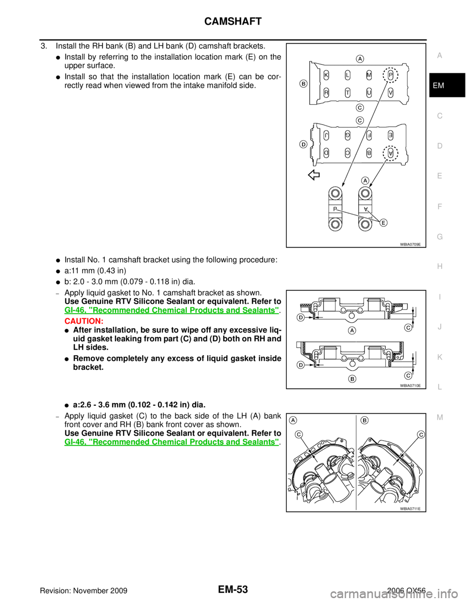
3. Install the RH bank (B) and LH bank (D) camshaft brackets.
�Install by referring to the installation location mark (E) on the
upper surface.
�Install so that the installation location mark (E) can be cor-
rectly read when viewed from the intake manifold side.
�Install No. 1 camshaft bracket using the following procedure:
�a:11 mm (0.43 in)
�b: 2.0 - 3.0 mm (0.079 - 0.118 in) dia.
–Apply liquid gasket to No. 1 camshaft bracket as shown.
Use Genuine RTV Silicone Sealant or equivalent. Refer to
GI-46, "
Recommended Chemical Products and Sealants".
CAUTION:
�After installation, be sure to wipe off any excessive liq-
uid gasket leaking from part (C) and (D) both on RH and
LH sides.
�Remove completely any excess of liquid gasket inside
bracket.
�a:2.6 - 3.6 mm (0.102 - 0.142 in) dia.
–Apply liquid gasket (C) to the back side of the LH (A) bank
front cover and RH (B) bank front cover as shown.
Use Genuine RTV Silicone Sealant or equivalent. Refer to
GI-46, "
Recommended Chemical Products and Sealants".
WBIA0709E
WBIA0710E
WBIA0711E
Page 1945 of 3383
EM-54Revision: November 2009
CAMSHAFT
2006 QX56
–Position No. 1 camshaft bracket close to the mounting posi-
tion, and then install it to prevent from touching liquid gasket
applied to each surface.
–Temporarily tighten the front cover bolts (4 for each bank) as
shown.
4. Tighten the camshaft bracket bolts as follows: CAUTION:
After tightening the camshaft bracket bolts, be sure to wipe
off excessive liquid gasket from the parts listed below.
�Mating surface of rocker cover
�Mating surface of front cover
a. Tighten the front cover bolts (4 for each bank) as shown to the specified torque.
SBIA0259E
WBIA0706E
Camshaft bracket bolts
Step 1 (bolts 9 - 12) : 2.0 N·m (0.2 kg-m, 17 in-lb)
Step 2 (bolts 1 - 8) : 2.0 N·m (0.2 kg-m, 17 in-lb)
Step 3 (all bolts) : 5.9 N·m (0.6 kg-m, 52 in-lb)
Step 4 (all bolts) : 10.4 N·m (1.1 kg-m, 92 in-lb)
WBIA0707E
Front cover bolts : 11.0 N·m (1.1 kg-m, 8 ft-lb)
WBIA0706E
Page 1955 of 3383
EM-64Revision: November 2009
CYLINDER HEAD
2006 QX56
Removal and InstallationEBS00RFE
REMOVAL
1. Remove the engine assembly from the vehicle. Refer to EM-74, "Removal and Installation" .
2. Remove the following components and related parts:
�Drive belt auto tensioner drive belts and idler pulley. Refer to EM-14, "REMOVAL" .
�Thermostat housing and hose. Refer to CO-21, "Removal and Installation" .
�Oil pan and oil strainer. Refer to EM-24, "Removal and Installation" .
�Fuel tube and fuel injector assembly. Refer to EM-31, "Removal and Installation" .
�Intake manifold. Refer to EM-17, "Removal and Installation" .
�Ignition coil. Refer to EM-28, "Removal and Installation" .
�Rocker cover. Refer to EM-35, "Removal and Installation" .
3. Remove the crankshaft pulley, front cover, oil pump, and timing chain. Refer to EM-37, "
Removal and
Installation" .
4. Remove the camshaft sprockets and camshafts. Refer to EM-46, "
Removal and Installation" .
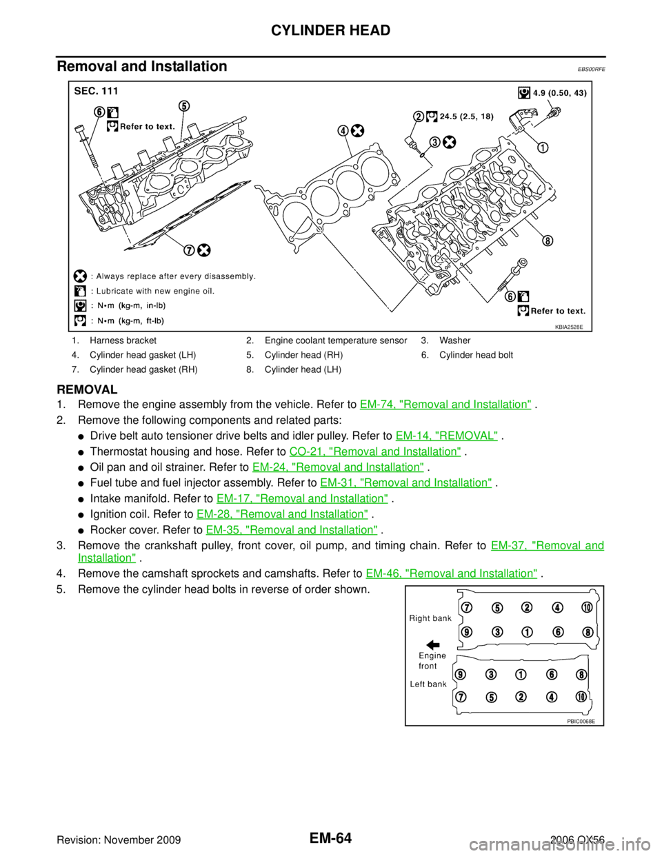
5. Remove the cylinder head bolts in reverse of order shown.
1. Harness bracket 2. Engine coolant temperature sensor 3. Washer
4. Cylinder head gasket (LH) 5. Cylinder head (RH) 6. Cylinder head bolt
7. Cylinder head gasket (RH) 8. Cylinder head (LH)
KBIA2528E
PBIC0068E
Page 1965 of 3383
EM-74Revision: November 2009
ENGINE ASSEMBLY
2006 QX56
ENGINE ASSEMBLYPFP:10001
Removal and InstallationEBS00RFH
WARNING:
�Situate vehicle on a flat and solid surface.
�Place chocks at front and back of rear wheels.
�For engines not equipped with engine slingers, attach proper slingers and bolts described in
PARTS CATALOG.
CAUTION:
�Always be careful to work safely, avoid forceful or uninstructed operations.
�Do not start working until exhaust system and engine coolant are cooled sufficiently.
�If items or work required are not covered by the engine section, refer to the applicable sections.
�Always use the support point specified for lifting.
�Use either 2-point lift type or separate type lift. If board-on type is used for unavoidable reasons,
support at the rear axle jacking point with transmission jack or similar tool before starting work, in
preparation for the backward shift of center of gravity.
�For supporting points for lifting and jacking point at rear axle, refer to GI-41, "Garage Jack and
Safety Stand" .
REMOVAL
Preparation
1. Drain the engine coolant. Refer to CO-11, "DRAINING ENGINE COOLANT" .
2. Partially drain the A/T fluid. Refer to AT- 1 2 , "
Changing Automatic Transmission Fluid (ATF)" .
3. Release the fuel pressure. Refer to EC-80, "
FUEL PRESSURE RELEASE"
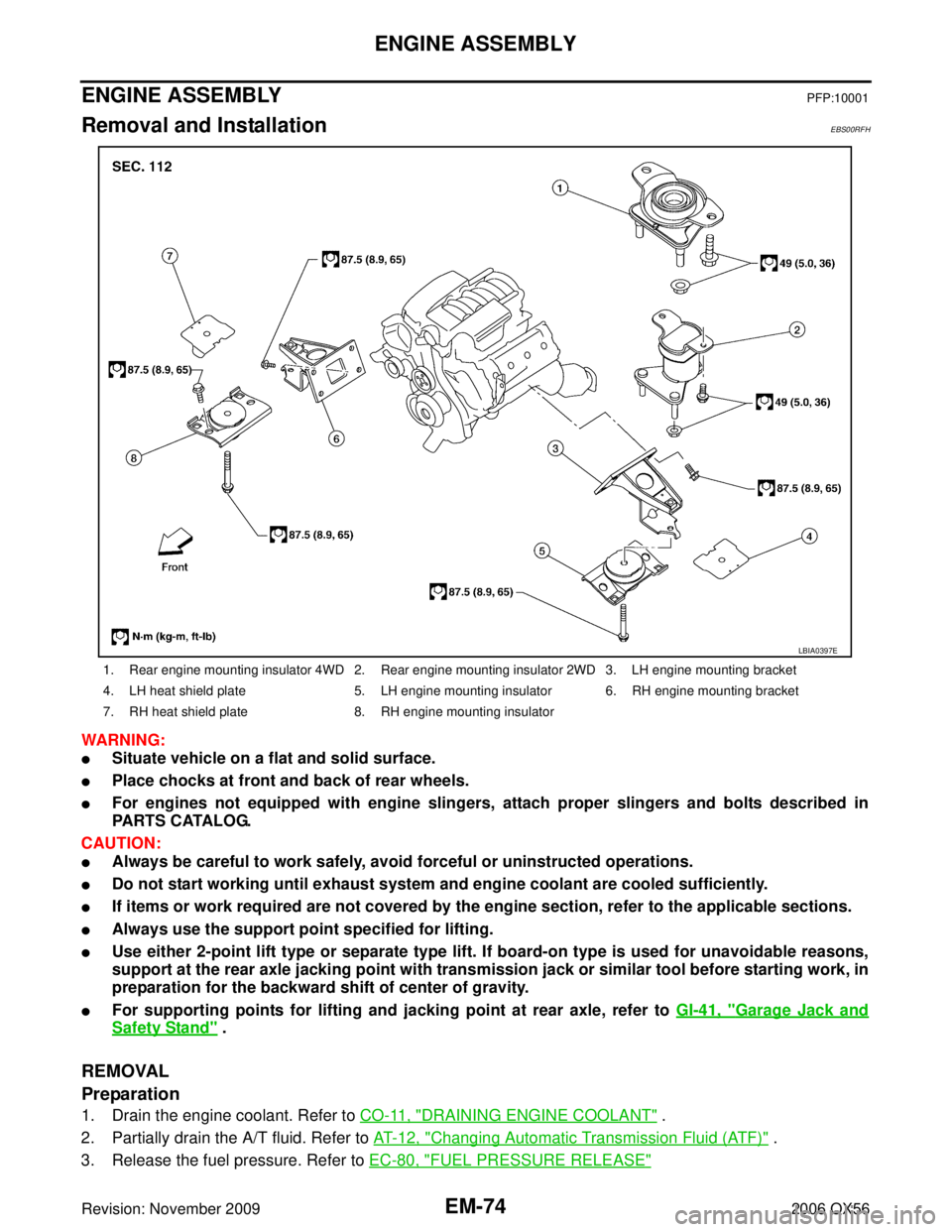
1. Rear engine mounting insulator 4WD 2. Rear engine mounting insulator 2WD 3. LH engine mounting bracket
4. LH heat shield plate 5. LH engine mounting insulator 6. RH engine mounting bracket
7. RH heat shield plate 8. RH engine mounting insulator
LBIA0397E
Page 1967 of 3383
EM-76Revision: November 2009
ENGINE ASSEMBLY
2006 QX56
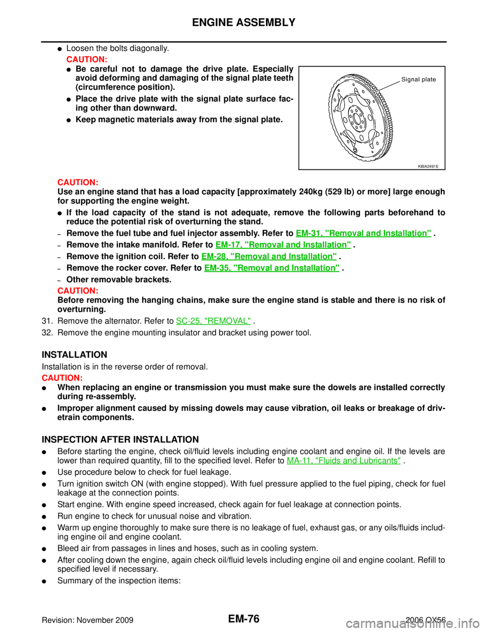
�Loosen the bolts diagonally.
CAUTION:
�Be careful not to damage the drive plate. Especially
avoid deforming and damaging of the signal plate teeth
(circumference position).
�Place the drive plate with the signal plate surface fac-
ing other than downward.
�Keep magnetic materials away from the signal plate.
CAUTION:
Use an engine stand that has a load capacity [approximately 240kg (529 lb) or more] large enough
for supporting the engine weight.
�If the load capacity of the stand is not adequate, remove the following parts beforehand to
reduce the potential risk of overturning the stand.
–Remove the fuel tube and fuel injector assembly. Refer to EM-31, "Removal and Installation" .
–Remove the intake manifold. Refer to EM-17, "Removal and Installation" .
–Remove the ignition coil. Refer to EM-28, "Removal and Installation" .
–Remove the rocker cover. Refer to EM-35, "Removal and Installation" .
–Other removable brackets.
CAUTION:
Before removing the hanging chains, make sure the engine stand is stable and there is no risk of
overturning.
31. Remove the alternator. Refer to SC-25, "
REMOVAL" .
32. Remove the engine mounting insulator and bracket using power tool.
INSTALLATION
Installation is in the reverse order of removal.
CAUTION:
�When replacing an engine or transmission you must make sure the dowels are installed correctly
during re-assembly.
�Improper alignment caused by missing dowels may cause vibration, oil leaks or breakage of driv-
etrain components.
INSPECTION AFTER INSTALLATION
�Before starting the engine, check oil/fluid levels including engine coolant and engine oil. If the levels are
lower than required quantity, fill to the specified level. Refer to MA-11, "
Fluids and Lubricants" .
�Use procedure below to check for fuel leakage.
�Turn ignition switch ON (with engine stopped). With fuel pressure applied to the fuel piping, check for fuel
leakage at the connection points.
�Start engine. With engine speed increased, check again for fuel leakage at connection points.
�Run engine to check for unusual noise and vibration.
�Warm up engine thoroughly to make sure there is no leakage of fuel, exhaust gas, or any oils/fluids includ-
ing engine oil and engine coolant.
�Bleed air from passages in lines and hoses, such as in cooling system.
�After cooling down the engine, again check oil/fluid levels including engine oil and engine coolant. Refill to
specified level if necessary.
�Summary of the inspection items:
KBIA2491E
Page 1996 of 3383
SERVICE DATA AND SPECIFICATIONS (SDS)EM-105
C
DE
F
G H
I
J
K L
M A
EM
Revision: November 2009 2006 QX56
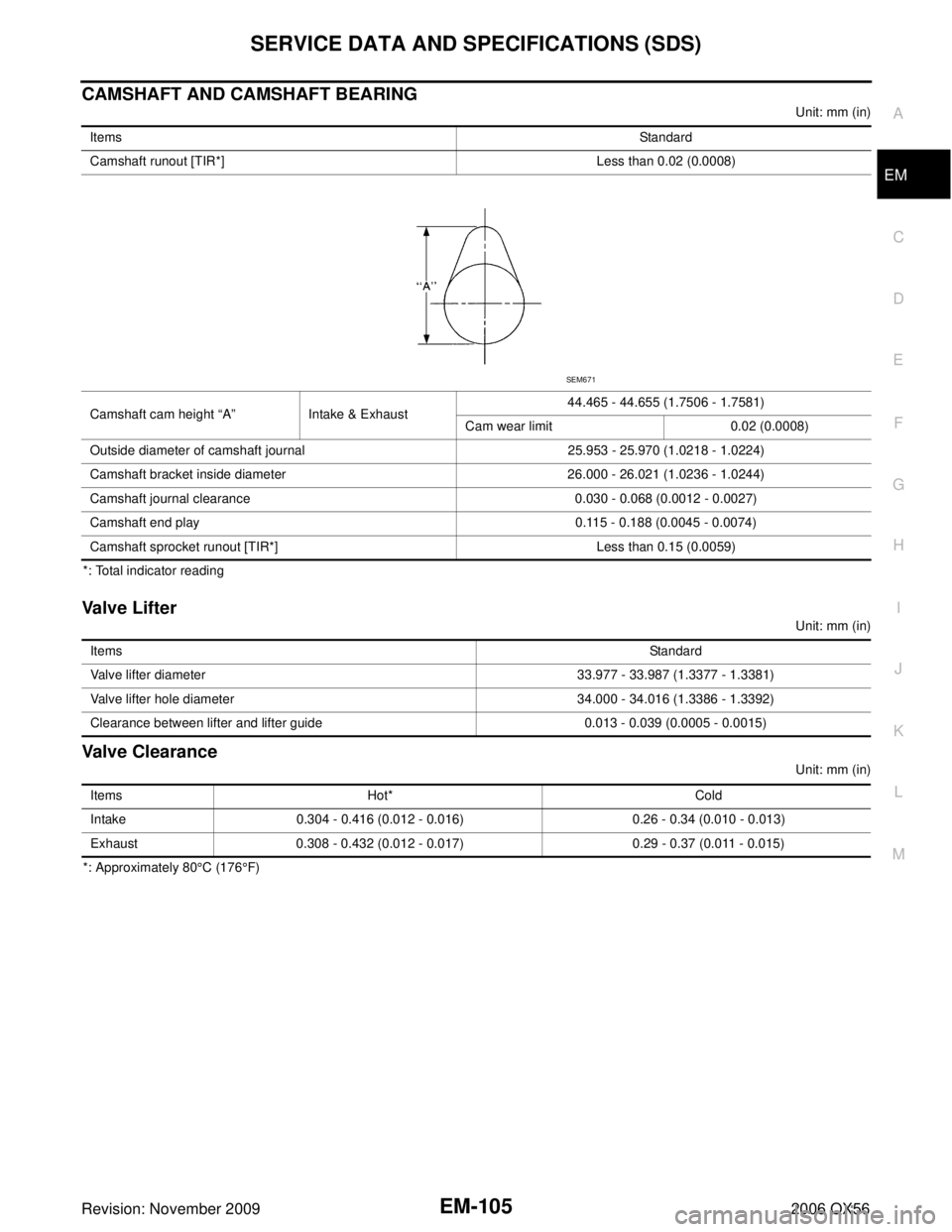
CAMSHAFT AND CAMSHAFT BEARING
Unit: mm (in)
*: Total indicator reading
Valve Lifter
Unit: mm (in)
Valve Clearance
Unit: mm (in)
*: Approximately 80 °C (176°F)
Items
Standard
Camshaft runout [TIR*] Less than 0.02 (0.0008)
Camshaft cam height “A ” Intake & Exhaust 44.465 - 44.655 (1.7506 - 1.7581)
Cam wear limit 0.02 (0.0008)
Outside diameter of camshaft journal 25.953 - 25.970 (1.0218 - 1.0224)
Camshaft bracket inside diameter 26.000 - 26.021 (1.0236 - 1.0244)
Camshaft journal clearance 0.030 - 0.068 (0.0012 - 0.0027)
Camshaft end play 0.115 - 0.188 (0.0045 - 0.0074)
Camshaft sprocket runout [TIR*] Less than 0.15 (0.0059)
SEM671
Items Standard
Valve lifter diameter 33.977 - 33.987 (1.3377 - 1.3381)
Valve lifter hole diameter 34.000 - 34.016 (1.3386 - 1.3392)
Clearance between lifter and lifter guide 0.013 - 0.039 (0.0005 - 0.0015)
Items Hot* Cold
Intake 0.304 - 0.416 (0.012 - 0.016) 0.26 - 0.34 (0.010 - 0.013)
Exhaust 0.308 - 0.432 (0.012 - 0.017) 0.29 - 0.37 (0.011 - 0.015)