Page 2076 of 3383
FRONT SUSPENSION ASSEMBLYFSU-5
C
DF
G H
I
J
K L
M A
B
FSU
Revision: November 2009 2006 QX56
FRONT SUSPENSION ASSEMBLYPFP:54010
ComponentsEES00257
1. Dust cover2. Shock absorber 3. Upper link
4. Steering knuckle 5. Cotter pin 6. Bolt
7. Jounce bumper 8. Washer 9. Lower link
10. Stabilizer bar 11. Stabilizer bar bushing 12. Stabilizer bar mounting bracket
13. Connecting rod 14. Coil spring 15. Upper seat
16. Upper spring seat 17. Shock absorber bushing 18. Shock absorber mounting insulator
19. Spacer 20. Washer ⇐Front
WEIA0156E
Page 2077 of 3383
FSU-6
ON-VEHICLE SERVICE
Revision: November 20092006 QX56
ON-VEHICLE SERVICEPFP:00000
Front Suspension PartsEES00258
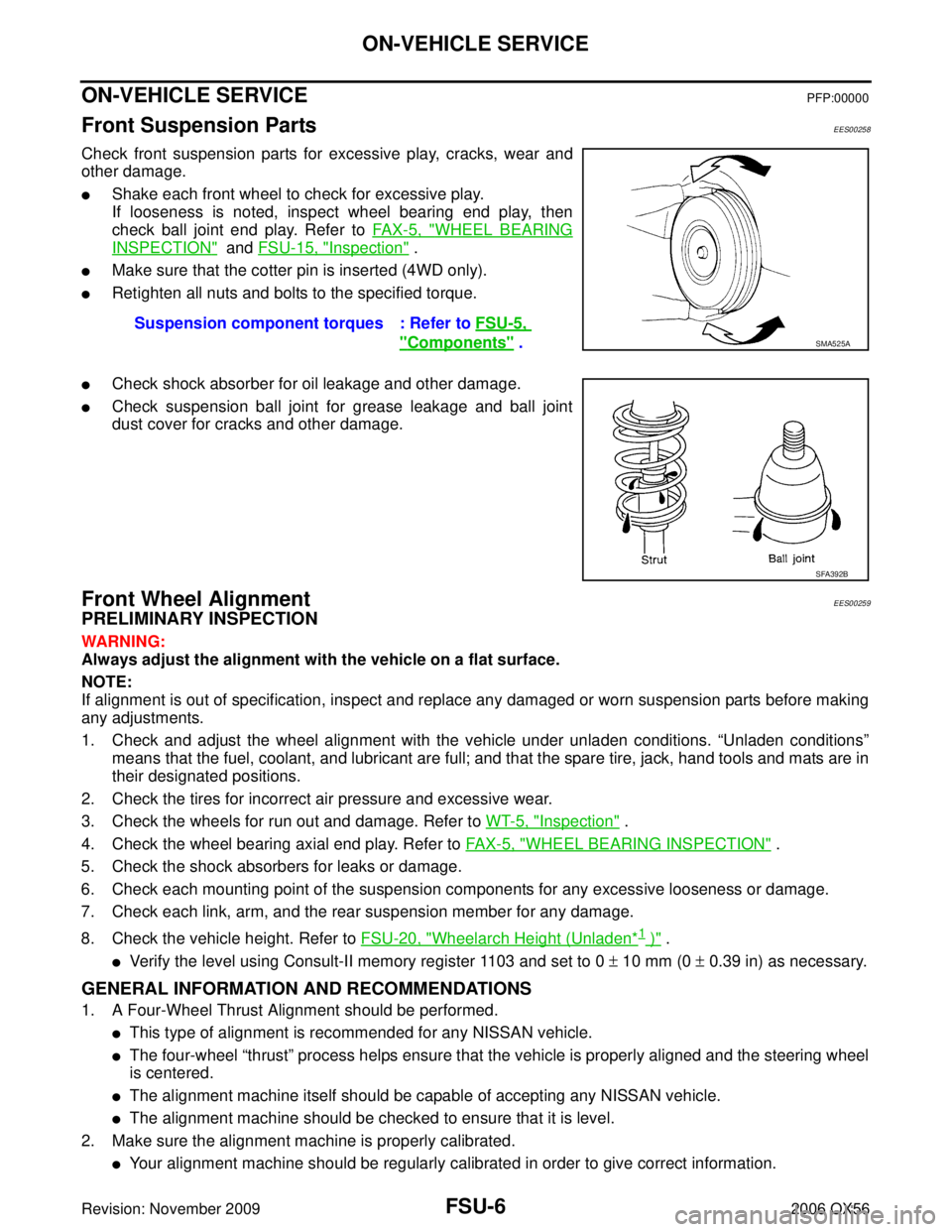
Check front suspension parts for excessive play, cracks, wear and
other damage.
�Shake each front wheel to check for excessive play.
If looseness is noted, inspect wheel bearing end play, then
check ball joint end play. Refer to FA X - 5 , "
WHEEL BEARING
INSPECTION" and FSU-15, "Inspection" .
�Make sure that the cotter pin is inserted (4WD only).
�Retighten all nuts and bolts to the specified torque.
�Check shock absorber for oil leakage and other damage.
�Check suspension ball joint for grease leakage and ball joint
dust cover for cracks and other damage.
Front Wheel AlignmentEES00259
PRELIMINARY INSPECTION
WARNING:
Always adjust the alignment with the vehicle on a flat surface.
NOTE:
If alignment is out of specification, inspect and replace any damaged or worn suspension parts before making
any adjustments.
1. Check and adjust the wheel alignment with the vehicle under unladen conditions. “Unladen conditions”
means that the fuel, coolant, and lubricant are full; and that the spare tire, jack, hand tools and mats are in
their designated positions.
2. Check the tires for incorrect air pressure and excessive wear.
3. Check the wheels for run out and damage. Refer to WT-5, "
Inspection" .
4. Check the wheel bearing axial end play. Refer to FA X - 5 , "
WHEEL BEARING INSPECTION" .
5. Check the shock absorbers for leaks or damage.
6. Check each mounting point of the suspension components for any excessive looseness or damage.
7. Check each link, arm, and the rear suspension member for any damage.
8. Check the vehicle height. Refer to FSU-20, "
Wheelarch Height (Unladen*1 )" .
�Verify the level using Consult-II memory register 1103 and set to 0 ± 10 mm (0 ± 0.39 in) as necessary.
GENERAL INFORMATION AND RECOMMENDATIONS
1. A Four-Wheel Thrust Alignment should be performed.
�This type of alignment is recommended for any NISSAN vehicle.
�The four-wheel “thrust” process helps ensure that the vehicle is properly aligned and the steering wheel
is centered.
�The alignment machine itself should be capable of accepting any NISSAN vehicle.
�The alignment machine should be checked to ensure that it is level.
2. Make sure the alignment machine is properly calibrated.
�Your alignment machine should be regularly calibrated in order to give correct information. Suspension component torques : Refer to
FSU-5,
"Components" . SMA525A
SFA392B
Page 2082 of 3383
COIL SPRING AND SHOCK ABSORBERFSU-11
C
DF
G H
I
J
K L
M A
B
FSU
Revision: November 2009 2006 QX56
INSPECTION AFTER DISASSEMBLY
Shock Absorber Assembly
�Check for smooth operation through a full stroke, both compression and extension.
�Check for oil leakage on welded or gland packing portions.
�Check piston rod for cracks, deformation or other damage and replace if necessary.
Mounting Insulator and Rubber Parts
Check cemented rubber-to-metal portion for separation or cracks. Check rubber parts for deterioration and
replace if necessary.
Coil Spring
�Check for cracks, deformation or other damage and replace if necessary.
�Check the free spring height.
ASSEMBLY
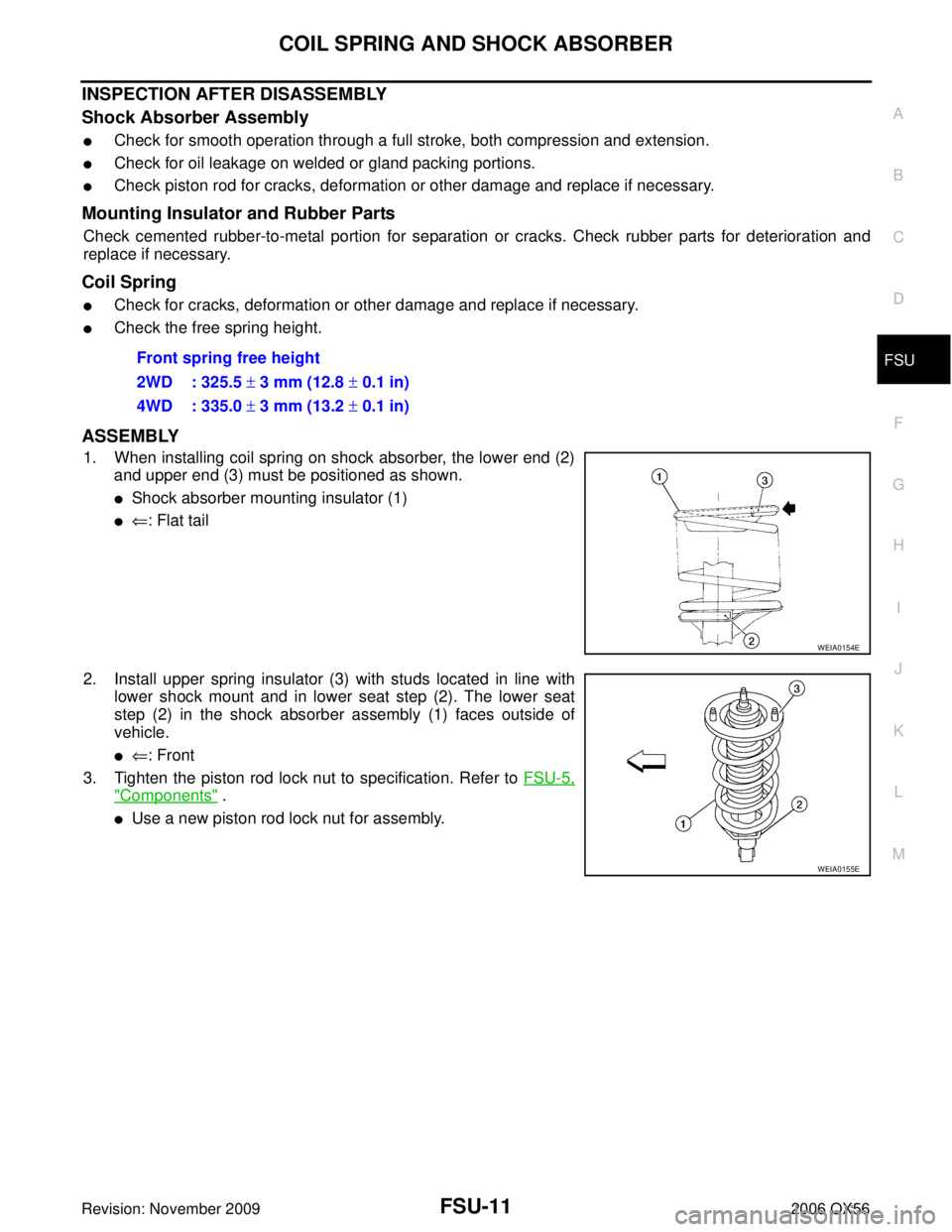
1. When installing coil spring on shock absorber, the lower end (2)
and upper end (3) must be positioned as shown.
�Shock absorber mounting insulator (1)
�⇐: Flat tail
2. Install upper spring insulator (3) with studs located in line with lower shock mount and in lower seat step (2). The lower seat
step (2) in the shock absorber assembly (1) faces outside of
vehicle.
�⇐: Front
3. Tighten the piston rod lock nut to specification. Refer to FSU-5,
"Components" .
�Use a new piston rod lock nut for assembly.Front spring free height
2WD : 325.5
± 3 mm (12.8 ± 0.1 in)
4WD : 335.0 ± 3 mm (13.2 ± 0.1 in)
WEIA0154E
WEIA0155E
Page 2083 of 3383
FSU-12
STABILIZER BAR
Revision: November 20092006 QX56
STABILIZER BARPFP:54611
Removal and InstallationEES0025C
REMOVAL
1. Remove engine under cover using power tool.
2. Remove stabilizer bar mounting bracket bolts and connecting
rod nuts using power tool, as shown.
3. Remove bushings from stabilizer bar.
INSPECTION AFTER REMOVAL
�Check stabilizer bar for twist and deformation. Replace if necessary.
�Check rubber bushing for cracks, wear and deterioration. Replace if necessary.
INSTALLATION
Installation is in the reverse order of removal.
�Tighten all nuts and bolts to specification. Refer to FSU-5, "Components" .
LEIA0094E
Page 2084 of 3383
UPPER LINKFSU-13
C
DF
G H
I
J
K L
M A
B
FSU
Revision: November 2009 2006 QX56
UPPER LINKPFP:54524
Removal and InstallationEES0025D
REMOVAL
1. Remove the wheel and tire using power tool.
2. Remove the fender protector to access upper link. Refer to EI-23, "
Removal and Installation" .
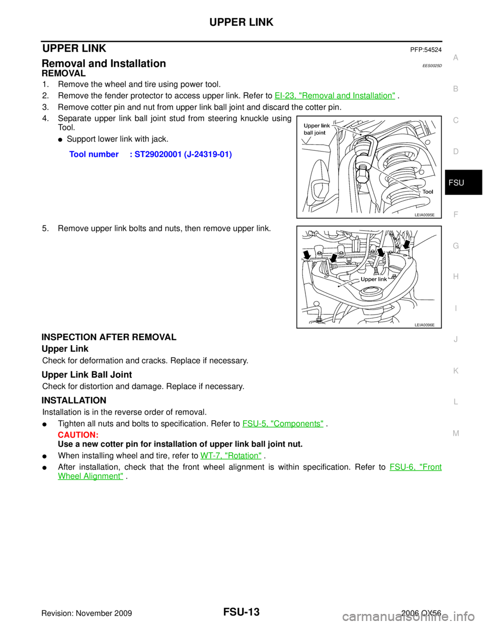
3. Remove cotter pin and nut from upper link ball joint and discard the cotter pin.
4. Separate upper link ball joint stud from steering knuckle using To o l .
�Support lower link with jack.
5. Remove upper link bolts and nuts, then remove upper link.
INSPECTION AFTER REMOVAL
Upper Link
Check for deformation and cracks. Replace if necessary.
Upper Link Ball Joint
Check for distortion and damage. Replace if necessary.
INSTALLATION
Installation is in the reverse order of removal.
�Tighten all nuts and bolts to specification. Refer to FSU-5, "Components" .
CAUTION:
Use a new cotter pin for installation of upper link ball joint nut.
�When installing wheel and tire, refer to WT-7, "Rotation" .
�After installation, check that the front wheel alignment is within specification. Refer to FSU-6, "Front
Wheel Alignment" .
Tool number : ST29020001 (J-24319-01)
LEIA0095E
LEIA0096E
Page 2085 of 3383
FSU-14
LOWER LINK
Revision: November 20092006 QX56
LOWER LINKPFP:55020
Removal and InstallationEES0025E
REMOVAL
1. Remove the wheel and tire using power tool.
2. Remove lower shock absorber bolt.
3. Remove stabilizer bar connecting rod lower nut using power tool, then separate connecting rod from lower
link. Refer to FSU-12, "
Removal and Installation" .
4. Remove drive shaft nut, if equipped. Refer to FA X - 7 , "
Removal and Installation" .
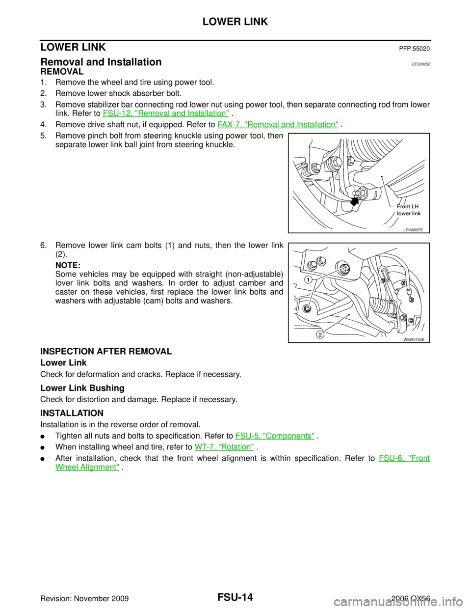
5. Remove pinch bolt from steering knuckle using power tool, then separate lower link ball joint from steering knuckle.
6. Remove lower link cam bolts (1) and nuts, then the lower link (2).
NOTE:
Some vehicles may be equipped with straight (non-adjustable)
lover link bolts and washers. In order to adjust camber and
caster on these vehicles, first replace the lower link bolts and
washers with adjustable (cam) bolts and washers.
INSPECTION AFTER REMOVAL
Lower Link
Check for deformation and cracks. Replace if necessary.
Lower Link Bushing
Check for distortion and damage. Replace if necessary.
INSTALLATION
Installation is in the reverse order of removal.
�Tighten all nuts and bolts to specification. Refer to FSU-5, "Components" .
�When installing wheel and tire, refer to WT-7, "Rotation" .
�After installation, check that the front wheel alignment is within specification. Refer to FSU-6, "Front
Wheel Alignment" .
LEIA0097E
WEIA0153E
Page 2089 of 3383
FSU-18
KNUCKLE
Revision: November 20092006 QX56
6. Separate upper link ball joint from steering knuckle using Tool.
7. Remove pinch bolt from steering knuckle using power tool, then
separate lower link ball joint from steering knuckle.
8. Remove steering knuckle from vehicle.
INSPECTION AFTER REMOVAL
Check for deformity, cracks and damage on each part, replace if necessary.
�Perform ball joint inspection. Refer to FSU-15, "Inspection" .
INSTALLATION
Installation is in the reverse order of removal.
�Refer to FSU-5, "Components" for tightening torques.
CAUTION:
Use a new cotter pin for installation of lock nut.
�When installing disc rotor on wheel hub and bearing assembly,
align the marks.
NOTE:
When not using the alignment mark, refer to BR-21, "
FRONT
DISC BRAKE" .
�When installing wheel and tire, refer to WT-7, "Rotation" .
Tool number : ST29020001 (J-24319-01)
LEIA0095E
LEIA0097E
WDIA0044E
Page 2120 of 3383
SERVICE INFORMATION FOR ELECTRICAL INCIDENTGI-29
C
DE
F
G H
I
J
K L
M B
GI
Revision: November 2009 2006 QX56
�Freezing
�Water intrusion
�Electrical load
�Cold or hot start up
Get a thorough description of the incident from the customer. It is important for simulating the conditions of the
problem.
Vehicle Vibration
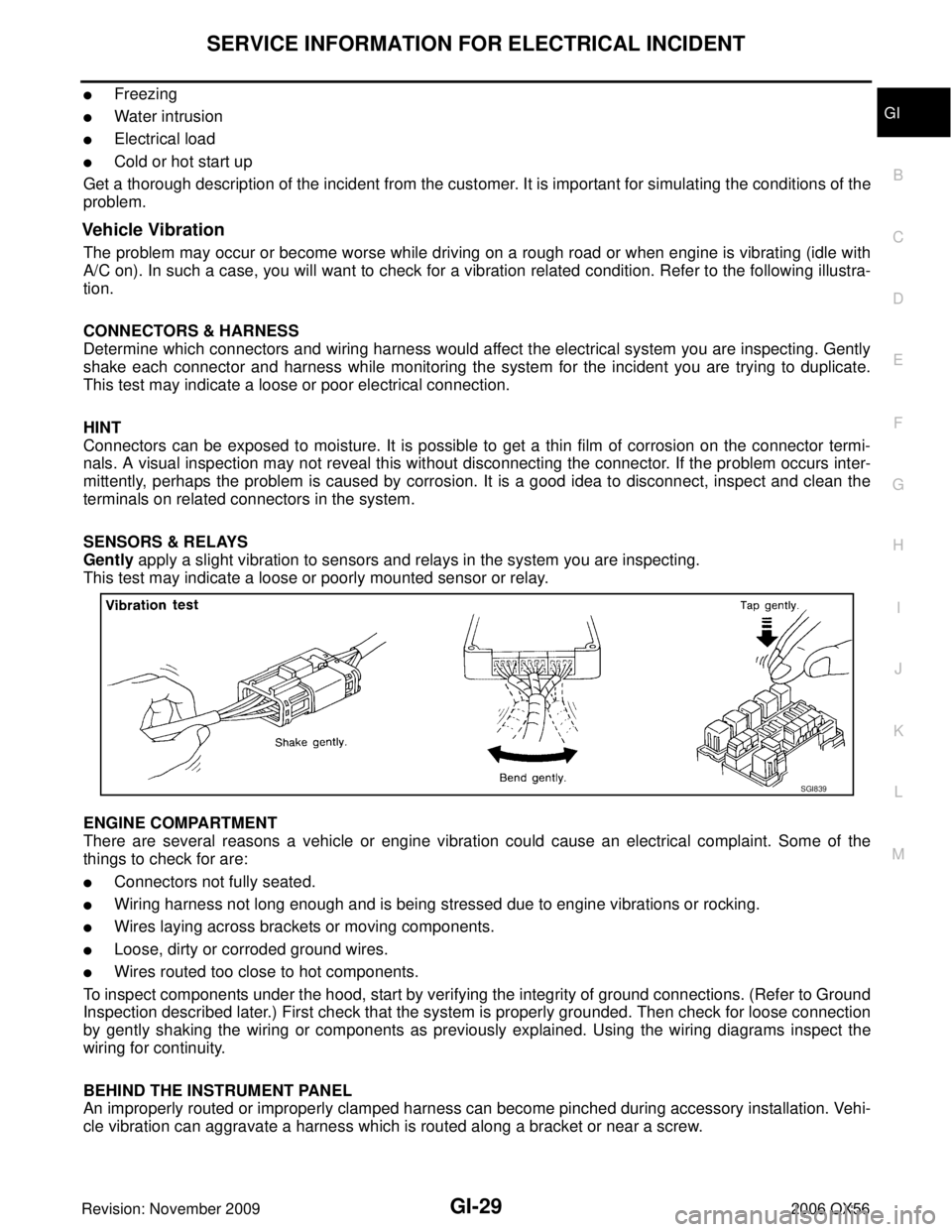
The problem may occur or become worse while driving on a rough road or when engine is vibrating (idle with
A/C on). In such a case, you will want to check for a vibration related condition. Refer to the following illustra-
tion.
CONNECTORS & HARNESS
Determine which connectors and wiring harness would affect the electrical system you are inspecting. Gently
shake each connector and harness while monitoring the system for the incident you are trying to duplicate.
This test may indicate a loose or poor electrical connection.
HINT
Connectors can be exposed to moisture. It is possible to get a thin film of corrosion on the connector termi-
nals. A visual inspection may not reveal this without disconnecting the connector. If the problem occurs inter-
mittently, perhaps the problem is caused by corrosion. It is a good idea to disconnect, inspect and clean the
terminals on related connectors in the system.
SENSORS & RELAYS
Gently apply a slight vibration to sensors and relays in the system you are inspecting.
This test may indicate a loose or poorly mounted sensor or relay.
ENGINE COMPARTMENT
There are several reasons a vehicle or engine vibration could cause an electrical complaint. Some of the
things to check for are:
�Connectors not fully seated.
�Wiring harness not long enough and is being stressed due to engine vibrations or rocking.
�Wires laying across brackets or moving components.
�Loose, dirty or corroded ground wires.
�Wires routed too close to hot components.
To inspect components under the hood, start by verifying the integrity of ground connections. (Refer to Ground
Inspection described later.) First check that the system is properly grounded. Then check for loose connection
by gently shaking the wiring or components as previously explained. Using the wiring diagrams inspect the
wiring for continuity.
BEHIND THE INSTRUMENT PANEL
An improperly routed or improperly clamped harness can become pinched during accessory installation. Vehi-
cle vibration can aggravate a harness which is routed along a bracket or near a screw.
SGI839