Page 1868 of 3383
COWL TOPEI-19
C
DE
F
G H
J
K L
M A
B
EI
Revision: November 2009 2006 QX56
�Cowl top extension bracket LH must be removed prior to removal of wiper motor and connecting rod
assembly.
6. Remove wiper motor and connecting rod linkage. Refer to WW-29, "
Wiper Motor and Linkage" .
7. Disconnect windshield washer tube. Refer to WW-30, "
Washer Tube Layout" .
8. Remove water cut valve bracket from cowl top extension. Refer to CO-21, "
THERMOSTAT AND WATER
PIPING" .
9. Remove A/C line bracket from cowl top extension. Refer to ATC-171, "
REFRIGERANT LINES" .
10. Remove drain tube from each side of cowl top extension.
11. Remove cowl top extension.
INSTALLATION
Installation is in the reverse order of removal.
Page 1874 of 3383
RUNNING BOARDSEI-25
C
DE
F
G H
J
K L
M A
B
EI
Revision: November 2009 2006 QX56
RUNNING BOARDSPFP:96110
Removal and InstallationEIS004WL
REMOVAL
1. Remove bolts and remove running board from running board brackets.
2. Remove nuts, then remove step pad from running board.
3. Remove nuts, then bolts and remove running board brackets.
4. Remove screws, then remove front and rear mud guards.
INSTALLATION
Installation is in the reverse order of removal.
1. Running board bracket2. Front mud guard3. Running board
4. Step pad 5. Rear mud guard
WIIA0960E
Page 1876 of 3383
ROOF RACKEI-27
C
DE
F
G H
J
K L
M A
B
EI
Revision: November 2009 2006 QX56
ROOF RACKPFP:73155
Removal and InstallationEIS004WN
REMOVAL
1. Remove screws, raise tie down hooks and remove finisher covers.
2. Remove bolts and remove front crossbar and gasket.
3. Remove screws, raise tie down hooks and remove slide rail covers.
4. Remove sliding crossbar.
5. Remove bolts and remove slide rails.
INSTALLATION
Installation is in the reverse order of removal.
�To install finisher covers and slide rail covers, rotate tie hooks to the 50 degrees up position and slip cover
over tie down. Press down until clip is engaged. Rotate tie down hook to the down position. then install
screws.
1. Sliding crossbar2. Finisher cover3. Front crossbar
4. Gasket 5. Slide rail6. Slide rail cover
WIIA0962E
Page 1888 of 3383

HEADLININGEI-39
C
DE
F
G H
J
K L
M A
B
EI
Revision: November 2009 2006 QX56
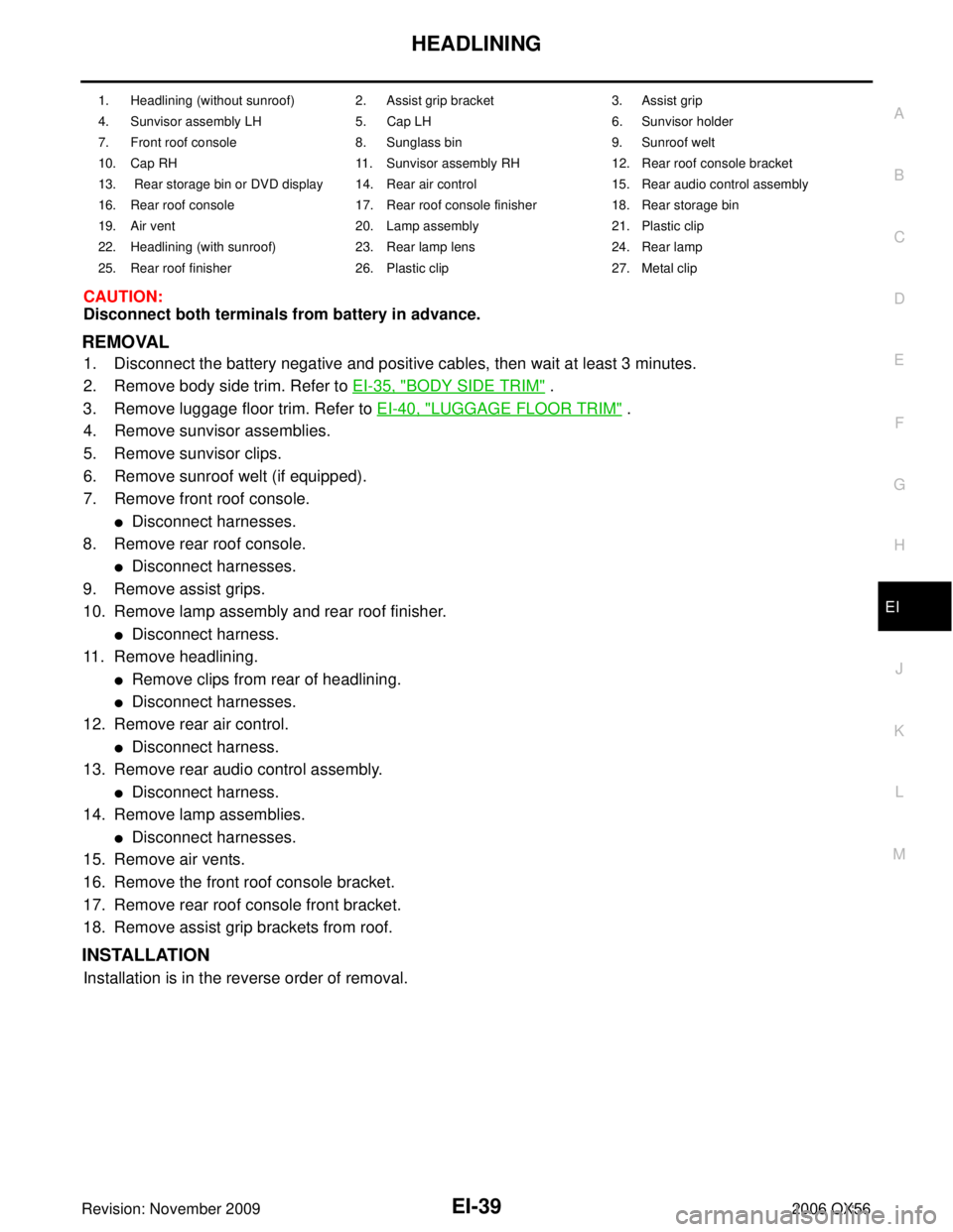
CAUTION:
Disconnect both terminals from battery in advance.
REMOVAL
1. Disconnect the battery negative and positive cables, then wait at least 3 minutes.
2. Remove body side trim. Refer to EI-35, "
BODY SIDE TRIM" .
3. Remove luggage floor trim. Refer to EI-40, "
LUGGAGE FLOOR TRIM" .
4. Remove sunvisor assemblies.
5. Remove sunvisor clips.
6. Remove sunroof welt (if equipped).
7. Remove front roof console.
�Disconnect harnesses.
8. Remove rear roof console.
�Disconnect harnesses.
9. Remove assist grips.
10. Remove lamp assembly and rear roof finisher.
�Disconnect harness.
11. Remove headlining.
�Remove clips from rear of headlining.
�Disconnect harnesses.
12. Remove rear air control.
�Disconnect harness.
13. Remove rear audio control assembly.
�Disconnect harness.
14. Remove lamp assemblies.
�Disconnect harnesses.
15. Remove air vents.
16. Remove the front roof console bracket.
17. Remove rear roof console front bracket.
18. Remove assist grip brackets from roof.
INSTALLATION
Installation is in the reverse order of removal.
1. Headlining (without sunroof) 2. Assist grip bracket 3. Assist grip
4. Sunvisor assembly LH 5. Cap LH 6. Sunvisor holder
7. Front roof console 8. Sunglass bin9. Sunroof welt
10. Cap RH 11. Sunvisor assembly RH12. Rear roof console bracket
13. Rear storage bin or DVD display 14. Rear air control 15. Rear audio control assembly
16. Rear roof console 17. Rear roof console finisher18. Rear storage bin
19. Air vent 20. Lamp assembly21. Plastic clip
22. Headlining (with sunroof) 23. Rear lamp lens24. Rear lamp
25. Rear roof finisher 26. Plastic clip27. Metal clip
Page 1890 of 3383

LUGGAGE FLOOR TRIMEI-41
C
DE
F
G H
J
K L
M A
B
EI
Revision: November 2009 2006 QX56
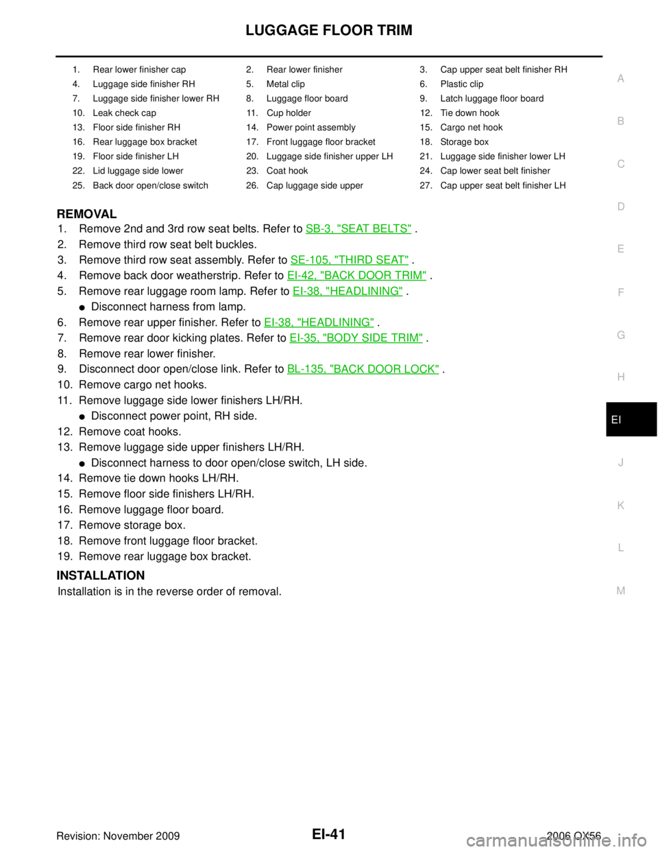
REMOVAL
1. Remove 2nd and 3rd row seat belts. Refer to SB-3, "SEAT BELTS" .
2. Remove third row seat belt buckles.
3. Remove third row seat assembly. Refer to SE-105, "
THIRD SEAT" .
4. Remove back door weatherstrip. Refer to EI-42, "
BACK DOOR TRIM" .
5. Remove rear luggage room lamp. Refer to EI-38, "
HEADLINING" .
�Disconnect harness from lamp.
6. Remove rear upper finisher. Refer to EI-38, "
HEADLINING" .
7. Remove rear door kicking plates. Refer to EI-35, "
BODY SIDE TRIM" .
8. Remove rear lower finisher.
9. Disconnect door open/close link. Refer to BL-135, "
BACK DOOR LOCK" .
10. Remove cargo net hooks.
11. Remove luggage side lower finishers LH/RH.
�Disconnect power point, RH side.
12. Remove coat hooks.
13. Remove luggage side upper finishers LH/RH.
�Disconnect harness to door open/close switch, LH side.
14. Remove tie down hooks LH/RH.
15. Remove floor side finishers LH/RH.
16. Remove luggage floor board.
17. Remove storage box.
18. Remove front luggage floor bracket.
19. Remove rear luggage box bracket.
INSTALLATION
Installation is in the reverse order of removal.
1. Rear lower finisher cap 2. Rear lower finisher3. Cap upper seat belt finisher RH
4. Luggage side finisher RH 5. Metal clip6. Plastic clip
7. Luggage side finisher lower RH 8. Luggage floor board 9. Latch luggage floor board
10. Leak check cap 11. Cup holder12. Tie down hook
13. Floor side finisher RH 14. Power point assembly 15. Cargo net hook
16. Rear luggage box bracket 17. Front luggage floor bracket 18. Storage box
19. Floor side finisher LH 20. Luggage side finisher upper LH 21. Luggage side finisher lower LH
22. Lid luggage side lower 23. Coat hook24. Cap lower seat belt finisher
25. Back door open/close switch 26. Cap luggage side upper 27. Cap upper seat belt finisher LH
Page 1902 of 3383

NOISE, VIBRATION, AND HARSHNESS (NVH) TROUBLESHOOTINGEM-11
C
DE
F
G H
I
J
K L
M A
EM
Revision: November 2009 2006 QX56
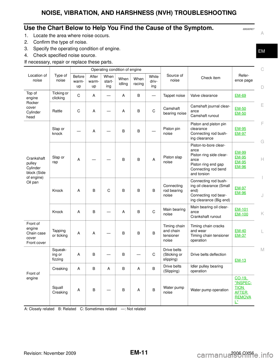
Use the Chart Below to Help You Find the Cause of the Symptom.EBS00RET
1. Locate the area where noise occurs.
2. Confirm the type of noise.
3. Specify the operating condition of engine.
4. Check specified noise source.
If necessary, repair or replace these parts.
A: Closely related B: Related C: Sometimes related—: Not related
Location of
noise Type of
noise Operating condition of engine
Source of noise Check item Refer-
ence page
Before
warm- up After
warm- up When
start- ing When
idling When
racing While
driv- ing
Top of
engine
Rocker
cover
Cylinder
head Ticking or
clicking
CA
—AB —Tappet noise Valve clearance EM-69
Rattle C A—ABC Camshaft
bearing noiseCamshaft journal clear-
ance
Camshaft runout EM-50EM-50
Crankshaft
pulley
Cylinder
block (Side
of engine)
Oil panSlap or
knock
—
A— BB —Piston pin
noise Piston and piston pin
clearance
Connecting rod bush-
ing clearance EM-95
EM-97
Slap or
rap
A
—— BBA Piston slap
noisePiston-to-bore clear-
ance
Piston ring side clear-
ance
Piston ring end gap
Connecting rod bend
and torsion EM-99EM-95
EM-95
EM-96
Knock A B C B B B
Connecting
rod bearing
noiseConnecting rod bush-
ing oil clearance (Small
end)
Connecting rod bear-
ing clearance (Big end)
EM-97EM-96
Knock A B
—ABC Main bearing
noiseMain bearing oil clear-
ance
Crankshaft runout EM-101EM-100
Front of
engine
Chain case
cover
Front coverTapping
or ticking
AA
—BBB Timing chain
and chain
tensioner
noiseTiming chain cracks
and wear
Timing chain tensioner
operation
EM-40
EM-37
Front of
engineSqueak-
ing or
fizzing
AB
—B— CDrive belts
(Sticking or
slipping) Drive belts deflection
EM-13
Creaking A B A B A B Drive belts
(Slipping)Idler pulley bearing
operation
Squall
Creaking AB
—BAB Water pump
noiseWater pump operation CO-19,
"INSPEC-
TION
AFTER
REMOVA
L"
Page 1904 of 3383

DRIVE BELTSEM-13
C
DE
F
G H
I
J
K L
M A
EM
Revision: November 2009 2006 QX56
DRIVE BELTSPFP:02117
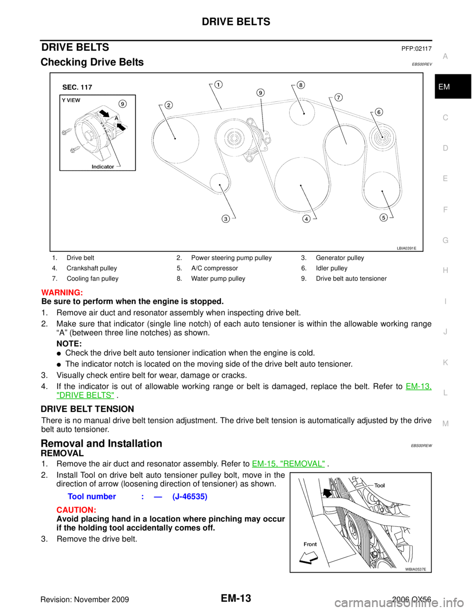
Checking Drive BeltsEBS00REV
WARNING:
Be sure to perform when the engine is stopped.
1. Remove air duct and resonator assembly when inspecting drive belt.
2. Make sure that indicator (single line notch) of each auto tensioner is within the allowable working range
“A” (between three line notches) as shown.
NOTE:
�Check the drive belt auto tensioner indication when the engine is cold.
�The indicator notch is located on the moving side of the drive belt auto tensioner.
3. Visually check entire belt for wear, damage or cracks.
4. If the indicator is out of allowable working range or belt is damaged, replace the belt. Refer to EM-13,
"DRIVE BELTS" .
DRIVE BELT TENSION
There is no manual drive belt tension adjustment. The drive belt tension is automatically adjusted by the drive
belt auto tensioner.
Removal and InstallationEBS00REW
REMOVAL
1. Remove the air duct and resonator assembly. Refer to EM-15, "REMOVAL" .
2. Install Tool on drive belt auto tensioner pulley bolt, move in the direction of arrow (loosening direction of tensioner) as shown.
CAUTION:
Avoid placing hand in a location where pinching may occur
if the holding tool accidentally comes off.
3. Remove the drive belt.
1. Drive belt 2. Power steering pump pulley 3. Generator pulley
4. Crankshaft pulley 5. A/C compressor6. Idler pulley
7. Cooling fan pulley 8. Water pump pulley9. Drive belt auto tensioner
LBIA0391E
Tool number : — (J-46535)
WBIA0537E
Page 1908 of 3383
INTAKE MANIFOLDEM-17
C
DE
F
G H
I
J
K L
M A
EM
Revision: November 2009 2006 QX56
INTAKE MANIFOLDPFP:14003
Removal and InstallationEBS00RF0
REMOVAL
1. Partially drain the engine coolant. Refer to CO-11, "DRAINING ENGINE COOLANT" .
WARNING:
To avoid the danger of being scalded, never drain the engine coolant when the engine is hot.
2. Remove the engine room cover using power tool. Refer to EM-12, "
REMOVAL" .
3. Release the fuel pressure. Refer to EC-80, "
FUEL PRESSURE RELEASE" .
4. Remove the air duct and resonator assembly. Refer to EM-15, "
REMOVAL" .
5. Disconnect the fuel tube quick connector on the engine side.
1. Intake manifold 2. PCV hose 3. Gasket
4. Electric throttle control actuator 5. Water hose 6. Water hose
7. PCV hose 8. EVAP hose 9. EVAP canister purge control sole-
noid valve
10. Bracket 11. Gasket
KBIA2461E
LBIA0395E