Page 653 of 3383
AV-60
AUDIO ANTENNA
Revision: November 20092006 QX56
AUDIO ANTENNAPFP:28200
System DescriptionEKS00BJ1
With the ignition switch in ACC or ON, power is supplied
�through 10A fuse [No. 4, located in the fuse block (J/B)]
�to audio unit terminal 10.
Ground is supplied through the case of the antenna amp.
When the audio unit switch is turned ON, antenna signal is supplied
�through audio unit terminal 5
�to the antenna amp. terminal 1.
Then the antenna amp. is activated.
The amplified radio signals are supplied to the audio unit through the antenna amp.
Page 657 of 3383
AV-64
TELEPHONE
Revision: November 20092006 QX56
TELEPHONEPFP:28342
Component Parts and Harness Connector LocationEKS00GC0
WKIA4565E
1. Fuse block (J/B)2. Fuse and fusible link box 3. Fuse and relay box
4. Combination meter M24 5. AV switch
M98 6. Audio unit
M45
7. BCM M18, M19 8. Steering wheel audio control
switches 9. Microphone
R108
10. Bluetooth ON indicator R16 11. Bluetooth control unit
B141, B142
(View with seat removed)
Page 668 of 3383
DVD ENTERTAINMENT SYSTEMAV-75
C
DE
F
G H
I
J
L
M A
B
AV
Revision: November 2009 2006 QX56
DVD ENTERTAINMENT SYSTEMPFP:28184
Component Parts and Harness Connector LocationEKS00BJ5
WKIA4570E
1. Fuse block (J/B)
M4 2. Fuse and fusible link box 3. Audio Unit
M46
4. DVD player M205, M206 5. Video Monitor
R202
Page 669 of 3383
AV-76
DVD ENTERTAINMENT SYSTEM
Revision: November 20092006 QX56
DescriptionEKS00BJ6
Refer to Owner's Manual for DVD entertainment system operating instructions.
Power is supplied at all times
�through 20A fuse (No. 31, located in the fuse and fusible link box)
�to DVD player terminal 16.
With the ignition switch in the ACC or ON position, power is supplied
�through 10A fuse [No. 4, located in the fuse block (J/B)]
�to DVD player terminal 15.
Power is also supplied
�from DVD player terminals 31 and 32
�to video monitor terminals 11 and 12.
Ground is supplied
�to DVD player terminal 22
�through body grounds M57, M61 and M79.
Audio signals are supplied
�through DVD player terminals 1, 2, 3 and 4
�to audio unit terminals 34, 35, 36 and 37.
Video signals are supplied
�through DVD player terminals 23, 24, 28 and 29
�to video monitor terminals 5, 6, 7 and 8.
Page 680 of 3383
NAVIGATION SYSTEMAV-87
C
DE
F
G H
I
J
L
M A
B
AV
Revision: November 2009 2006 QX56
Component Parts LocationEKS00BJF
WKIA4571E
1. Fuse block (J/B)2. Fuse and fusible link box 3. Combination switch
M28
4. Combination meter M24 5. GPS antenna
6. Display unit
M93
7. Display control unit M94, M95 8. AV switch
M98 9. Audio unit
M45
10. Data link connector M22 11 . B C M
M18, M20 12. Steering wheel audio control switches
13. NAVI control unit B151, B152, B154 14. IPDM E/R
E121, E124
Page 705 of 3383
AV-112
NAVIGATION SYSTEM
Revision: November 20092006 QX56
Self-Diagnosis Mode (DCU)EKS00GDZ
OPERATION PROCEDURE
1. Start the engine.
2. Turn the audio system off.
3. While pressing the “MEMORY 4” button, turn the volume control
dial clockwise or counterclockwise for 30 clicks or more. (When
the self-diagnosis mode is started, a short beep will be heard.)
�Shifting from current screen to previous screen is performed
by pressing “BACK” button.
4. The initial self-diagnosis screen will be shown, and items “Self- Diagnosis (DCU) ”, “Self-Diagnosis (NAVI) ”, “Confirmation/
Adjustment” and “CAN DIAG SUPPORT MONITOR ” will
become selective.
5. Perform self-diagnosis by selecting the “Self-Diagnosis”.
�Self-diagnosis subdivision screen will be shown and the oper-
ation enters the self-diagnosis mode.
�A bar graph shown below the self-diagnosis subdivision
screen indicates progress of the diagnosis.
WKIA4439E
SKIA4207E
SKIA4208E
Page 707 of 3383

AV-114
NAVIGATION SYSTEM
Revision: November 20092006 QX56
Self-Diagnosis Codes
Self-Diagnosis Mode (NAVI)EKS00GE0
OPERATION PROCEDURE
1. Start the engine.
2. Turn the audio system off.
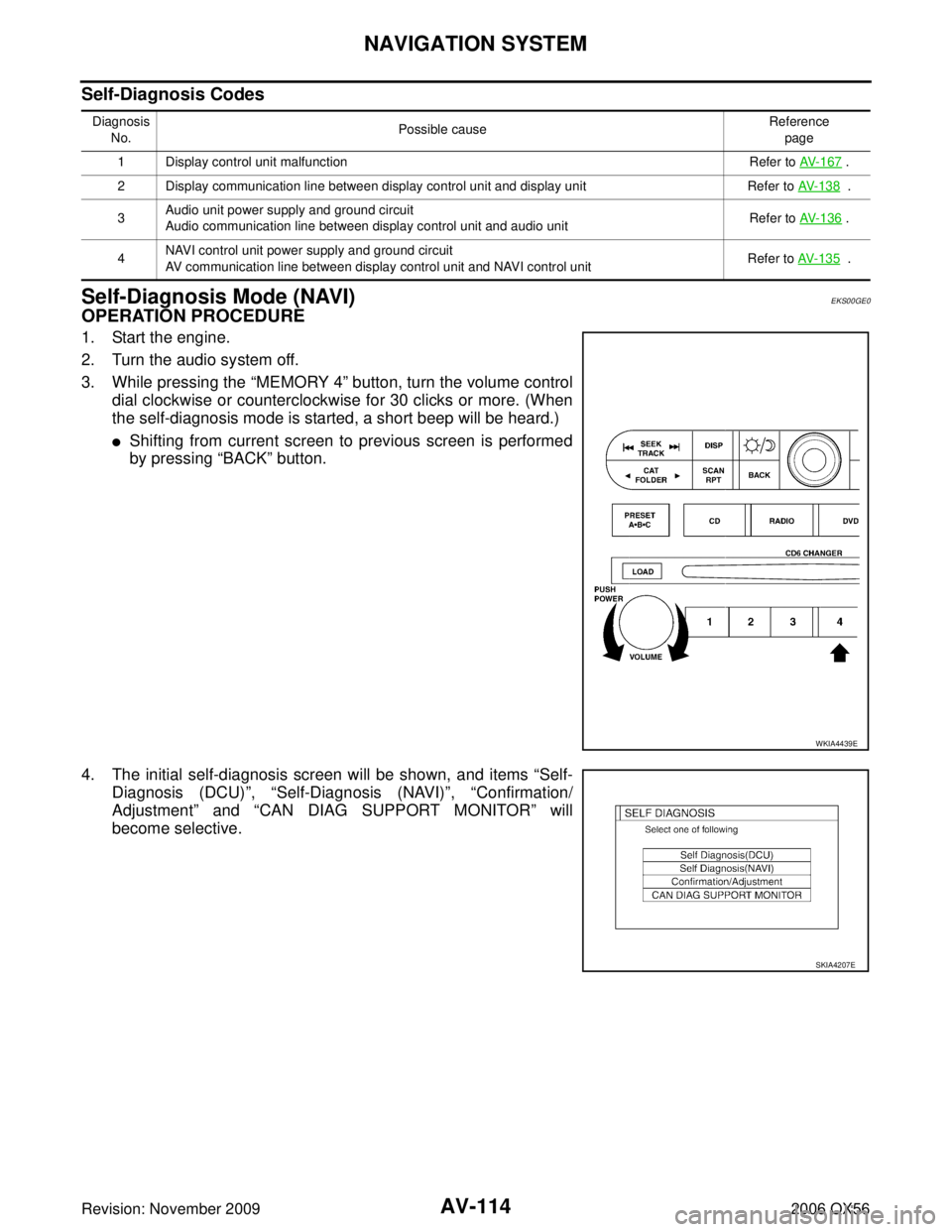
3. While pressing the “MEMORY 4” button, turn the volume control
dial clockwise or counterclockwise for 30 clicks or more. (When
the self-diagnosis mode is started, a short beep will be heard.)
�Shifting from current screen to previous screen is performed
by pressing “BACK” button.
4. The initial self-diagnosis screen will be shown, and items “Self- Diagnosis (DCU) ”, “Self-Diagnosis (NAVI) ”, “Confirmation/
Adjustment” and “CAN DIAG SUPPORT MONITOR ” will
become selective.
Diagnosis
No. Possible cause
Reference
page
1 Display control unit malfunction Refer to AV-167
.
2 Display communication line between display control unit and display unit Refer to AV-138
.
3 Audio unit power supply and ground circuit
Audio communication line between display control unit and audio unit
Refer to
AV-136
.
4 NAVI control unit power supply and ground circuit
AV communication line between display control unit and NAVI control unit Refer to AV-135
.
WKIA4439E
SKIA4207E
Page 710 of 3383

NAVIGATION SYSTEMAV-117
C
DE
F
G H
I
J
L
M A
B
AV
Revision: November 2009 2006 QX56
Confirmation/Adjustment ModeEKS00GE1
OPERATION PROCEDURE
1. Start the engine.
2. Turn the audio system off.
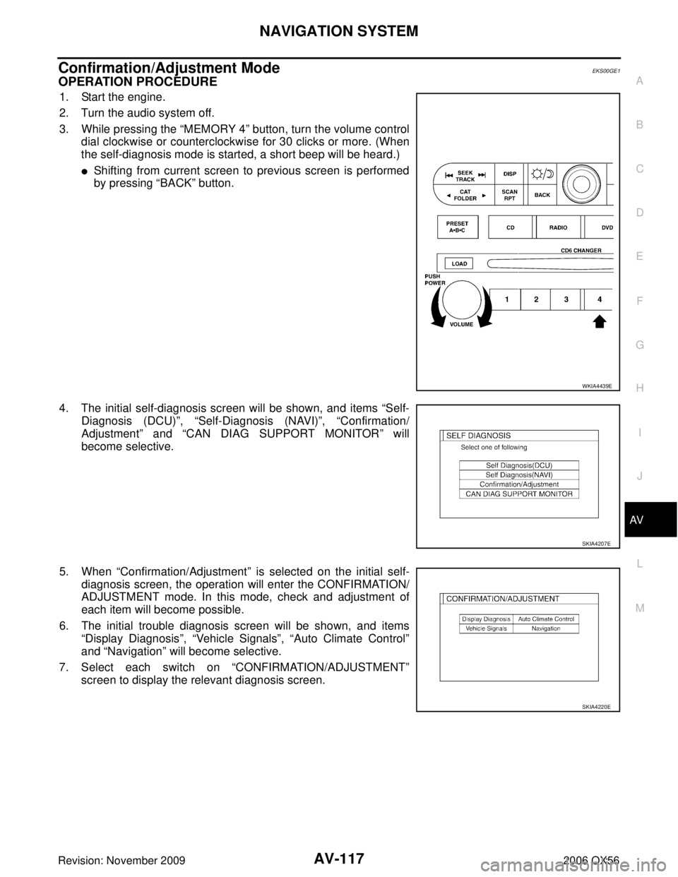
3. While pressing the “MEMORY 4” button, turn the volume control
dial clockwise or counterclockwise for 30 clicks or more. (When
the self-diagnosis mode is started, a short beep will be heard.)
�Shifting from current screen to previous screen is performed
by pressing “BACK” button.
4. The initial self-diagnosis screen will be shown, and items “Self-
Diagnosis (DCU) ”, “Self-Diagnosis (NAVI) ”, “Confirmation/
Adjustment ” and “CAN DIAG SUPPORT MONITOR ” will
become selective.
5. When “Confirmation/Adjustment ” is selected on the initial self-
diagnosis screen, the operation will enter the CONFIRMATION/
ADJUSTMENT mode. In this mode, check and adjustment of
each item will become possible.
6. The initial trouble diagnosis screen will be shown, and items “Display Diagnosis ”, “Vehicle Signals ”, “Auto Climate Control ”
and “Navigation ” will become selective.
7. Select each switch on “CONFIRMATION/ADJUSTMENT ”
screen to display the relevant diagnosis screen.
WKIA4439E
SKIA4207E
SKIA4220E