2006 INFINITI M35 START CAR WITH MANUAL KEY
[x] Cancel search: START CAR WITH MANUAL KEYPage 945 of 5621

BL-6
PRECAUTIONS
Revision: 2006 January2006 M35/M45
PRECAUTIONSPFP:00001
Precautions for Supplemental Restraint System (SRS) “AIR BAG” and “SEAT
BELT PRE-TENSIONER”
NIS001WA
The Supplemental Restraint System such as “AIR BAG” and “SEAT BELT PRE-TENSIONER”, used along
with a front seat belt, helps to reduce the risk or severity of injury to the driver and front passenger for certain
types of collision. This system includes seat belt switch inputs and dual stage front air bag modules. The SRS
system uses the seat belt switches to determine the front air bag deployment, and may only deploy one front
air bag, depending on the severity of a collision and whether the front occupants are belted or unbelted.
Information necessary to service the system safely is included in the SRS and SB section of this Service Man-
ual.
WAR NING :
To avoid rendering the SRS inoperative, which could increase the risk of personal injury or death
in the event of a collision which would result in air bag inflation, all maintenance must be per-
formed by an authorized NISSAN/INFINITI dealer.
Improper maintenance, including incorrect removal and installation of the SRS, can lead to per-
sonal injury caused by unintentional activation of the system. For removal of Spiral Cable and Air
Bag Module, see the SRS section.
Do not use electrical test equipment on any circuit related to the SRS unless instructed to in this
Service Manual. SRS wiring harnesses can be identified by yellow and/or orange harnesses or
harness connectors.
Precautions for Procedures without Cowl Top CoverNIS001WB
When performing the procedure after removing cowl top cover, cover
the lower end of windshield with urethane, etc.
Precautions Necessary for Steering Wheel Rotation after Battery DisconnectNIS001WC
NOTE:
Before removing and installing any control units, first turn the push-button ignition switch to the LOCK
position, then disconnect both battery cables.
After finishing work, confirm that all control unit connectors are connected properly, then re-connect both
battery cables.
Always use CONSULT-II to perform self-diagnosis as a part of each function inspection after finishing
work. If a DTC is detected, perform trouble diagnosis according to self-diagnosis results.
This vehicle is equipped with a push-button ignition switch and a steering lock unit.
If the battery is disconnected or discharged, the steering wheel will lock and cannot be turned.
If turning the steering wheel is required with the battery disconnected or discharged, follow the procedure
below before starting the repair operation.
OPERATION PROCEDURE
1. Connect both battery cables.
NOTE:
Supply power using jumper cables if battery is discharged.
2. Carry the Intelligent Key or insert it to the key slot and turn the push-button ignition switch to ACC position.
(At this time, the steering lock will be released.)
3. Disconnect both battery cables. The steering lock will remain released with both battery cables discon-
nected and the steering wheel can be turned.
4. Perform the necessary repair operation.
PIIB3706J
Page 1089 of 5621
BL-150
INTELLIGENT KEY SYSTEM/ENGINE START FUNCTION
Revision: 2006 January2006 M35/M45
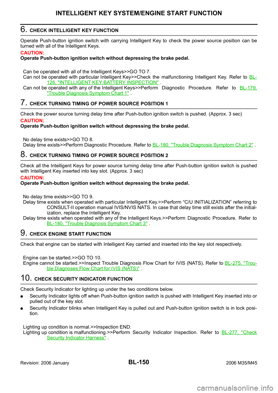
6. CHECK INTELLIGENT KEY FUNCTION
Operate Push-button ignition switch with carrying Intelligent Key to check the power source position can be
turned with all of the Intelligent Keys.
CAUTION:
Operate Push-button ignition switch without depressing the brake pedal.
Can be operated with all of the Intelligent Keys>>GO TO 7.
Can not be operated with particular Intelligent Key>>Check the malfunctioning Intelligent Key. Refer to BL-
126, "INTELLIGENT KEY BATTERY INSPECTION" .
Can not be operated with any of the Intelligent Keys>>Perform Diagnostic Procedure. Refer to BL-179,
"Trouble Diagnosis Symptom Chart 1" .
7. CHECK TURNING TIMING OF POWER SOURCE POSITION 1
Check the power source turning delay time after Push-button ignition switch is pushed. (Approx. 3 sec)
CAUTION:
Operate Push-button ignition switch without depressing the brake pedal.
No delay time exists>>GO TO 8.
Delay time exists>>Perform Diagnostic Procedure. Refer to BL-180, "
Trouble Diagnosis Symptom Chart 2" .
8. CHECK TURNING TIMING OF POWER SOURCE POSITION 2
Check all the Intelligent Keys for power source turning delay time after Push-button ignition switch is pushed
with Intelligent Key inserted into key slot. (Approx. 3 sec)
CAUTION:
Operate Push-button ignition switch without depressing the brake pedal.
No delay time exists>>GO TO 9.
Delay time exists when operated with particular Intelligent Key.>>Perform “C/U INITIALIZATION” referring to
CONSULT-II operation manual IVIS/NVIS NATS. In case that delay time still exists after the initial-
ization, replace the Intelligent Key.
Delay time exists when operated with any of the Intelligent Keys.>>Perform Diagnostic Procedure. Refer to
BL-180, "
Trouble Diagnosis Symptom Chart 3" .
9. CHECK ENGINE START FUNCTION
Check that engine can be started with Intelligent Key carried and inserted into the key slot respectively.
Engine can be started.>>GO TO 10.
Engine cannot be started.>>Inspect Trouble Diagnosis Flow Chart for IVIS (NATS). Refer to BL-275, "
Trou-
ble Diagnoses Flow Chart for IVIS (NATS)" .
10. CHECK SECURITY INDICATOR FUNCTION
Check Security Indicator for lighting up under the two conditions below.
Security Indicator lights off when Push-button ignition switch is pushed with Intelligent Key inserted into or
pulled out of the key slot.
Security Indicator blinks when Intelligent Key is pulled out and Push-button ignition switch is in lock posi-
tion.
Lighting up condition is normal.>>Inspection END.
Lighting up condition is malfunctioning.>>Perform Security Indicator Inspection. Refer to BL-277, "
Check
Security Indicator Harness" .
Page 1189 of 5621

BL-250
IVIS (INFINITI VEHICLE IMMOBILIZER SYSTEM-NATS)
Revision: 2006 January2006 M35/M45
System DescriptionNIS0020D
DESCRIPTION
The IVIS (NATS) is an anti-theft system by registering an Intelligent Key ID in to the vehicle and prevents
the engine being started by an unregistered Intelligent Key. It has a higher protection against auto thefts
that duplicates mechanical key.
It performs the ID verification when starting the engine in the same way as the Intelligent Key system. But,
it performs the IVIS (NATS) ID verification when inserting the Intelligent Key and performs the Intelligent
Key ID verification when carrying the Intelligent Key.
The Intelligent Key system of FUGA (Y50) is not the same as the conventional models. The mechanical
key integrated in the Intelligent Key cannot start the engine. When the Intelligent Key battery is dis-
charged, the IVIS (NATS) ID verification memorized to the transponder integrated with Intelligent Key is
performed by inserting the Intelligent Key into the key slot. If the verification results are OK, the engine
start operation can be performed by the push-button ignition switch operation.
Locate the security indicator and apply the anti-theft system equipment sticker, forewarn that the IVIS
(NATS) is onboard with the model.
The security indicator always blinks when the Intelligent Key is removed from the key slot and when the
power supply position is in LOCK position.
Intelligent Key can be registered up to 4 keys (Including the standard ignition key) on request from the
owner.
The specified registration is required when replacing ECM, BCM or Intelligent Key. The registrations pro-
cedure for IVIS (NATS) and registration procedure for Intelligent Key when installing the Intelligent Key
unit, refer to CONSULT-II Operation Manual NATS-IVIS/NVIS.
Possible symptom of IVIS (NATS) malfunction is “Engine cannot start”. In FUGA (Y50), the engine can be
started with the Intelligent Key system and IVIS (NATS). Identify the possible causes according to “Work
Flow”, Refer to BL-272, "
Work Flow" .
If ECM other than Genuine NISSAN is installed, the engine cannot be started. For ECM replacement pro-
cedure, refer to BL-252, "
ECM Re-Communicating Function" .
PRECAUTIONS FOR KEY REGISTRATION
The key registration is a procedure that erases the current IVIS (NATS) ID once, and then re register a
new ID operation. Therefore the registered Intelligent Key is necessary for this procedure. Before starting
the registration operation collect all registered Intelligent Key from the customer
When registering the Intelligent Key, 2 registration procedures [IVIS (NATS) ID registration and Intelligent
Key ID registration] should be performed. The IVIS (NATS) ID registration is the procedure that registers
the ID stored into the transponder (integrated into Intelligent Key) to the BCM. The Intelligent Key ID reg-
istration is the procedure that registers the ID to the Intelligent Key unit. Each registration procedure
should be done separated.
When performing the Intelligent Key system registration only, the engine cannot be started by inserting the
key into the key slot. When performing the IVIS (NATS) registration only, the engine cannot be started by
the operation when carrying the key. The registrations of both systems should be performed.
SECURITY INDICATOR
Warn the outside that the vehicle is the model with IVIS (NATS).
The security indicator always blinks when the Intelligent Key is removed from the key slot and when the
ignition switch is in LOCK position.
NOTE:
Because security indicator is highly efficient, the battery is barely affected.
Page 1213 of 5621
BL-274
IVIS (INFINITI VEHICLE IMMOBILIZER SYSTEM-NATS)
Revision: 2006 January2006 M35/M45
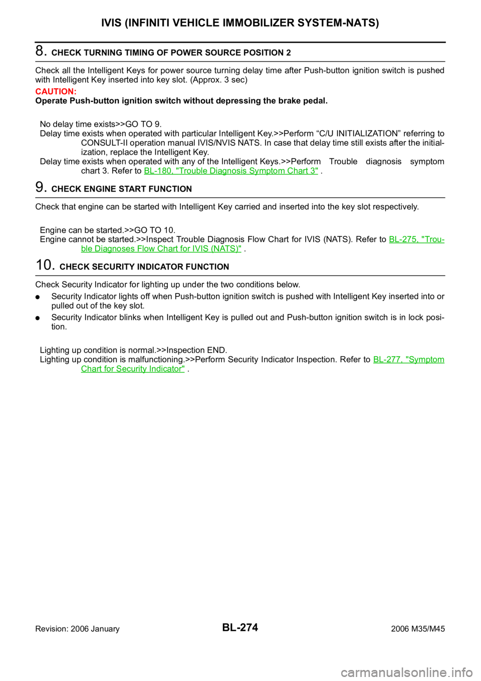
8. CHECK TURNING TIMING OF POWER SOURCE POSITION 2
Check all the Intelligent Keys for power source turning delay time after Push-button ignition switch is pushed
with Intelligent Key inserted into key slot. (Approx. 3 sec)
CAUTION:
Operate Push-button ignition switch without depressing the brake pedal.
No delay time exists>>GO TO 9.
Delay time exists when operated with particular Intelligent Key.>>Perform “C/U INITIALIZATION” referring to
CONSULT-II operation manual IVIS/NVIS NATS. In case that delay time still exists after the initial-
ization, replace the Intelligent Key.
Delay time exists when operated with any of the Intelligent Keys.>>Perform Trouble diagnosis symptom
chart 3. Refer to BL-180, "
Trouble Diagnosis Symptom Chart 3" .
9. CHECK ENGINE START FUNCTION
Check that engine can be started with Intelligent Key carried and inserted into the key slot respectively.
Engine can be started.>>GO TO 10.
Engine cannot be started.>>Inspect Trouble Diagnosis Flow Chart for IVIS (NATS). Refer to BL-275, "
Trou-
ble Diagnoses Flow Chart for IVIS (NATS)" .
10. CHECK SECURITY INDICATOR FUNCTION
Check Security Indicator for lighting up under the two conditions below.
Security Indicator lights off when Push-button ignition switch is pushed with Intelligent Key inserted into or
pulled out of the key slot.
Security Indicator blinks when Intelligent Key is pulled out and Push-button ignition switch is in lock posi-
tion.
Lighting up condition is normal.>>Inspection END.
Lighting up condition is malfunctioning.>>Perform Security Indicator Inspection. Refer to BL-277, "
Symptom
Chart for Security Indicator" .
Page 3466 of 5621

PRECAUTIONS
GI-3
C
D
E
F
G
H
I
J
K
L
MB
GI
Revision: 2006 January2006 M35/M45
PRECAUTIONSPFP:00001
DescriptionNAS00073
Observe the following precautions to ensure safe and proper servicing. These precautions are not
described in each individual section.
Precautions for Supplemental Restraint System (SRS) “AIR BAG” and “SEAT
BELT PRE-TENSIONER”
NAS00074
The Supplemental Restraint System such as “AIR BAG” and “SEAT BELT PRE-TENSIONER”, used along
with a front seat belt, helps to reduce the risk or severity of injury to the driver and front passenger for certain
types of collision. This system includes seat belt switch inputs and dual stage front air bag modules. The SRS
system uses the seat belt switches to determine the front air bag deployment, and may only deploy one front
air bag, depending on the severity of a collision and whether the front occupants are belted or unbelted.
Information necessary to service the system safely is included in the SRS and SB section of this Service Man-
ual.
WAR NING :
To avoid rendering the SRS inoperative, which could increase the risk of personal injury or death
in the event of a collision which would result in air bag inflation, all maintenance must be per-
formed by an authorized NISSAN/INFINITI dealer.
Improper maintenance, including incorrect removal and installation of the SRS, can lead to per-
sonal injury caused by unintentional activation of the system. For removal of Spiral Cable and Air
Bag Module, see the SRS section.
Do not use electrical test equipment on any circuit related to the SRS unless instructed to in this
Service Manual. SRS wiring harnesses can be identified by yellow and/or orange harnesses or
harness connectors.
Precautions for NVIS/IVIS (NISSAN/INFINITI VEHICLE IMMOBILIZER SYSTEM -
NATS) (If Equipped)
NAS00075
NVIS/IVIS (NATS) will immobilize the engine if someone tries to start it without the registered key of NVIS/IVIS
(NATS).
Both of the originally supplied ignition key IDs have been NVIS/IVIS (NATS) registered.
The security indicator is located on the instrument panel. The indicator blinks when the immobilizer system is
functioning.
Therefore, NVIS/IVIS (NATS) warns outsiders that the vehicle is equipped with the anti-theft system.
When NVIS/IVIS (NATS) detects trouble, the security indicator lamp lights up while ignition switch is in
"ON" position.
This lighting up indicates that the anti-theft is not functioning, so prompt service is required.
When servicing NVIS/IVIS (NATS) (trouble diagnoses, system initialization and additional registration of
other NVIS/IVIS (NATS) ignition key IDs), CONSULT-II hardware and CONSULT-II NVIS/IVIS (NATS)
software is necessary.
Regarding the procedures of NVIS/IVIS (NATS) initialization and NVIS/IVIS (NATS) ignition key ID regis-
tration, refer to CONSULT-II operation manual, NVIS/IVIS (NATS).
Therefore, CONSULT-II NVIS/IVIS (NATS) software (program card and operation manual) must be kept
strictly confidential to maintain the integrity of the anti-theft function.
When servicing NVIS/IVIS (NATS) (trouble diagnoses, system initialization and additional registration of
other NVIS/IVIS (NATS) ignition key IDs), it may be necessary to re-register original key identification.
Therefore, be sure to receive all keys from vehicle owner. A maximum of four or five key IDs can be regis-
tered into NVIS/IVIS (NATS).
When failing to start the engine first time using the key of NVIS/IVIS (NATS), start as follows.
1. Leave the ignition key in "ON" position for approximately 5 seconds.
2. Turn ignition key to "OFF" or "LOCK" position and wait approximately 5 seconds.
3. Repeat step 1 and 2 again.
4. Restart the engine while keeping the key separate from any others on key-chain.
Page 4956 of 5621

PRECAUTIONS
PS-3
C
D
E
F
H
I
J
K
L
MA
B
PS
Revision: 2006 January2006 M35/M45
PRECAUTIONSPFP:00001
Precautions for Supplemental Restraint System (SRS) “AIR BAG” and “SEAT
BELT PRE-TENSIONER”
NGS000CZ
The Supplemental Restraint System such as “AIR BAG” and “SEAT BELT PRE-TENSIONER”, used along
with a front seat belt, helps to reduce the risk or severity of injury to the driver and front passenger for certain
types of collision. This system includes seat belt switch inputs and dual stage front air bag modules. The SRS
system uses the seat belt switches to determine the front air bag deployment, and may only deploy one front
air bag, depending on the severity of a collision and whether the front occupants are belted or unbelted.
Information necessary to service the system safely is included in the SRS and SB section of this Service Man-
ual.
WAR NING :
To avoid rendering the SRS inoperative, which could increase the risk of personal injury or death
in the event of a collision which would result in air bag inflation, all maintenance must be per-
formed by an authorized NISSAN/INFINITI dealer.
Improper maintenance, including incorrect removal and installation of the SRS, can lead to per-
sonal injury caused by unintentional activation of the system. For removal of Spiral Cable and Air
Bag Module, see the SRS section.
Do not use electrical test equipment on any circuit related to the SRS unless instructed to in this
Service Manual. SRS wiring harnesses can be identified by yellow and/or orange harnesses or
harness connectors.
Precautions Necessary for Steering Wheel Rotation after Battery DisconnectNGS000D0
NOTE:
Before removing and installing any control units, first turn the push-button ignition switch to the LOCK
position, then disconnect both battery cables.
After finishing work, confirm that all control unit connectors are connected properly, then re-connect both
battery cables.
Always use CONSULT-II to perform self-diagnosis as a part of each function inspection after finishing
work. If a DTC is detected, perform trouble diagnosis according to self-diagnosis results.
This vehicle is equipped with a push-button ignition switch and a steering lock unit.
If the battery is disconnected or discharged, the steering wheel will lock and cannot be turned.
If turning the steering wheel is required with the battery disconnected or discharged, follow the procedure
below before starting the repair operation.
OPERATION PROCEDURE
1. Connect both battery cables.
NOTE:
Supply power using jumper cables if battery is discharged.
2. Carry the Intelligent Key or insert it to the key slot and turn the push-button ignition switch to ACC position.
(At this time, the steering lock will be released.)
3. Disconnect both battery cables. The steering lock will remain released with both battery cables discon-
nected and the steering wheel can be turned.
4. Perform the necessary repair operation.
5. When the repair work is completed, re-connect both battery cables. With the brake pedal released, turn
the push-button ignition switch from ACC position to ON position, then to LOCK position. (The steering
wheel will lock when the push-button ignition switch is turned to LOCK position.)
6. Perform self-diagnosis check of all control units using CONSULT-II.