Page 5324 of 5621

HEATED SEAT
SE-143
C
D
E
F
G
H
J
K
L
MA
B
SE
Revision: 2006 January2006 M35/M45
HEATED SEATPFP:87335
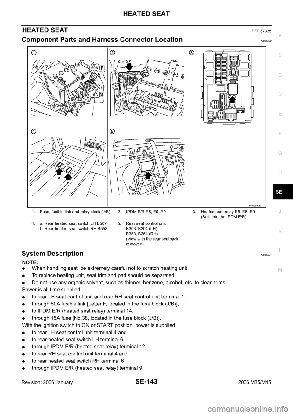
Component Parts and Harness Connector LocationNIS00280
System Description NIS00281
NOTE:
When handling seat, be extremely careful not to scratch heating unit
To replace heating unit, seat trim and pad should be separated.
Do not use any organic solvent, such as thinner, benzene, alcohol, etc. to clean trims.
Power is all time supplied
to rear LH seat control unit and rear RH seat control unit terminal 1.
through 50A fusible link [Letter F, located in the fuse block (J/B)],
to IPDM E/R (heated seat relay) terminal 14.
through 15A fuse [No.38, located in the fuse block (J/B)].
With the ignition switch to ON or START position, power is supplied
to rear LH seat control unit terminal 4 and
to rear heated seat switch LH terminal 6.
through IPDM E/R (heated seat relay) terminal 12
to rear RH seat control unit terminal 4 and
to rear heated seat switch RH terminal 6
through IPDM E/R (heated seat relay) terminal 9.
1. Fuse, fusible link and relay block (J/B) 2. IPDM E/R E5, E6, E93. Heated seat relay E5, E6, E9
(Built into the IPDM E/R)
4. a: Rear heated seat switch LH B507
b: Rear heated seat switch RH B5585. Rear seat control unit
B303, B304 (LH)
B353, B354 (RH)
(View with the rear seatback
removed)
PIIB5890E
Page 5333 of 5621

SE-152
HEATED SEAT
Revision: 2006 January2006 M35/M45
Rear Heated Seat Power Supply and Ground Circuit InspectionNIS00287
1. CHECK FUSIBLE LINK AND FUSE
Check 50A fusible link (letter F located in the fuse and fusible link box).
Check 15A fuse (No.38, located in fuse block).
Check circuit breaker.
NOTE:
Refer to SE-143, "
Component Parts and Harness Connector Location" .
OK or NG
OK >> GO TO 2.
NG >> If fuse or circuit breaker is blown, be sure to eliminate cause of malfunction before installing new
fuse or new circuit breaker, refer to PG-3, "
POWER SUPPLY ROUTING CIRCUIT" .
2. CHECK HEATED SEAT RELAY POWER SUPPLY CIRCUIT
1. Turn ignition switch OFF.
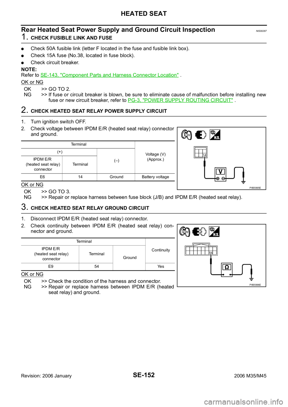
2. Check voltage between IPDM E/R (heated seat relay) connector
and ground.
OK or NG
OK >> GO TO 3.
NG >> Repair or replace harness between fuse block (J/B) and IPDM E/R (heated seat relay).
3. CHECK HEATED SEAT RELAY GROUND CIRCUIT
1. Disconnect IPDM E/R (heated seat relay) connector.
2. Check continuity between IPDM E/R (heated seat relay) con-
nector and ground.
OK or NG
OK >> Check the condition of the harness and connector.
NG >> Repair or replace harness between IPDM E/R (heated
seat relay) and ground.
Terminal
Voltage (V)
(Approx.) (+)
(–) IPDM E/R
(heated seat relay)
connectorTerminal
E6 14 Ground Battery voltage
PIIB5995E
Te r m i n a l
Continuity IPDM E/R
(heated seat relay)
connectorTerminal
Ground
E9 54 Yes
PIIB5996E
Page 5345 of 5621

SE-164
FRONT SEAT
Revision: 2006 January2006 M35/M45
1. Front leg cover 2. Rear leg cover 3. Headrest
4. Seatback board 5. Seat speaker grill 6. Headrest holder (free)
7. Headrest holder (locked) 8. Seatback upper finisher 9. Side air bag module
10. Reclining device cover 11. Seatback trim 12. Seatback pad
13. Seatback frame 14. Seat speaker 15. Seatback thermal electrical device
(TED) assembly
16. Seat cushion rear finisher
(Climate controlled seat model)17. Seat cushion front finisher 18. Seat slide switch knob
19. Seat reclining switch knob 20. Seat cushion outer finisher 21. Lumber support switch assembly
22. Seat cushion lower finisher 23. Seat cushion inner finisher 24.Seat cushion pad
25. Seat cushion trim 26. Seat cushion finisher B 27. Seat cushion frame
28. Seat cushion thermal electrical
device (TED) assembly29. Blower motor assembly 30. Climate controlled seat control unit
31. Seat control switch 32. Driver seat control unit 33. Seat cushion finisher C
34. Seat harness 35. Seat belt buckle 36. Seat adjuster assembly
Page 5347 of 5621
SE-166
FRONT SEAT
Revision: 2006 January2006 M35/M45
1. Front leg cover 2. Rear leg cover 3. Headrest
4. Seatback board 5. Seat speaker grill 6. Headrest holder (free)
7. Headrest holder (locked) 8. Seatback upper finisher 9. Side air bag module
10. Reclining device cover 11. Seatback trim 12. Seatback pad
13. Seatback frame 14. Seat speaker 15. Seatback thermal electrical device
(TED) assembly
16. Seat cushion rear finisher
(Climate controlled seat model)17. Seat cushion front finisher 18. Seat cushion slide switch
19. Seat reclining switch 20. Seat cushion outer finisher 21. Seat inner finisher
22. Seat cushion finisher B 23. Blower motor assembly 24. Seat cushion thermal electrical
device (TED) assembly
25. Climate controlled seat control unit 26. Seat cushion finisher C 27. Seat harness assembly
28. Seat belt buckle 29. Seat cushion assembly
Page 5354 of 5621
REAR SEAT
SE-173
C
D
E
F
G
H
J
K
L
MA
B
SE
Revision: 2006 January2006 M35/M45
1. Seat cushion trim 2. Seat cushion pad 3. Seatback pad
4. Seatback trim 5. Seat belt guide 6. Headrest holder (locked)
7. Headrest holder (free) 8. Headrest (left) 9. Headrest (center)
10. Headrest (right) 11. Armrest
Page 5356 of 5621
REAR SEAT
SE-175
C
D
E
F
G
H
J
K
L
MA
B
SE
Revision: 2006 January2006 M35/M45
1. Seat cushion side trim 2. Seat cushion center trim 3. Seat cushion side pad
4. Seat cushion center pad 5. Seatback trim 6. Seatback pad
7. Seatback center 8. Headrest (right) 9. Headrest (left)
10. Headrest (center) 11. Headrest holder (free) 12. Headrest holder (locked)
13. Seat belt guide 14. Rear seat frame 15. Rear seat control unit
16. Rear seat harness 17. Seatback hook 18. Seat cushion hook
Page 5357 of 5621

SE-176
REAR SEAT
Revision: 2006 January2006 M35/M45
Removal and InstallationNIS0028K
CAUTION:
When removing and installing, use shop cloths to protect parts from damage.
BENCH SEAT
Removal
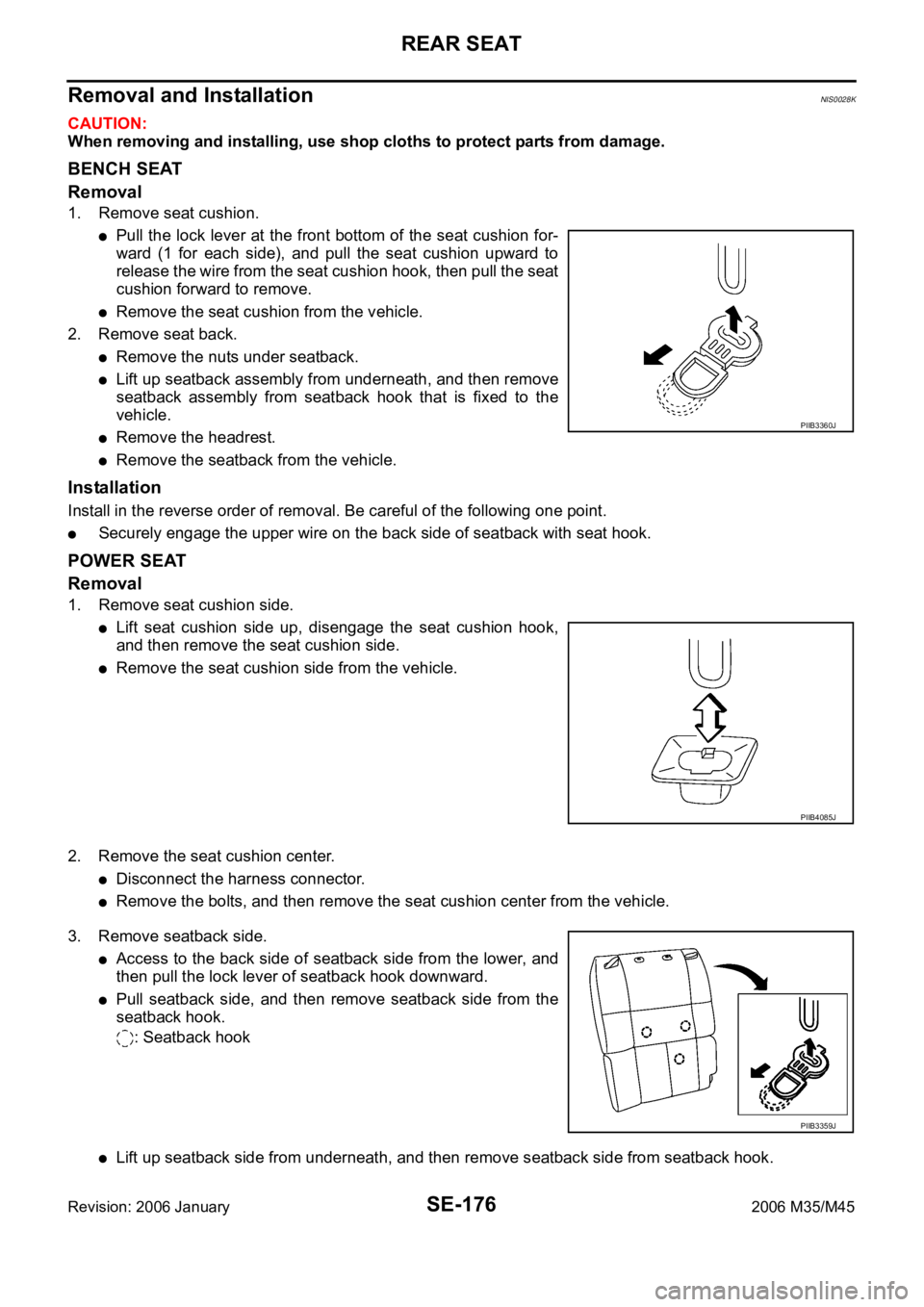
1. Remove seat cushion.
Pull the lock lever at the front bottom of the seat cushion for-
ward (1 for each side), and pull the seat cushion upward to
release the wire from the seat cushion hook, then pull the seat
cushion forward to remove.
Remove the seat cushion from the vehicle.
2. Remove seat back.
Remove the nuts under seatback.
Lift up seatback assembly from underneath, and then remove
seatback assembly from seatback hook that is fixed to the
vehicle.
Remove the headrest.
Remove the seatback from the vehicle.
Installation
Install in the reverse order of removal. Be careful of the following one point.
Securely engage the upper wire on the back side of seatback with seat hook.
POWER SEAT
Removal
1. Remove seat cushion side.
Lift seat cushion side up, disengage the seat cushion hook,
and then remove the seat cushion side.
Remove the seat cushion side from the vehicle.
2. Remove the seat cushion center.
Disconnect the harness connector.
Remove the bolts, and then remove the seat cushion center from the vehicle.
3. Remove seatback side.
Access to the back side of seatback side from the lower, and
then pull the lock lever of seatback hook downward.
Pull seatback side, and then remove seatback side from the
seatback hook.
: Seatback hook
Lift up seatback side from underneath, and then remove seatback side from seatback hook.
PIIB3360J
PIIB4085J
PIIB3359J
Page 5359 of 5621
SE-178
REAR SEAT
Revision: 2006 January2006 M35/M45
Install hog rings of seat cushion trim in position, and then
securely connect the trim or trim code with the pad side wire.
Disassembly of Armrest
1. Remove the armrest from seatback.
Remove the retainer from the side of armrest lid in the back.
Remove the armrest mounting nuts on the back of seatback.
2. Disassemble the armrest.
Remove the screws, and then remove armrest lid hinge.
Remove the armrest lid.
Remove screws, and then remove the armrest lock assembly from the armrest lid.
PIIB3356J
1. Armrest lid hinge 2. Armrest lid 3. Armrest lock assembly
4. Armrest assembly 5. Rear seat box
PIIB4685J