2006 INFINITI M35 lock
[x] Cancel search: lockPage 5077 of 5621

RFD-34
REAR FINAL DRIVE ASSEMBLY
Revision: 2006 January2006 M35/M45
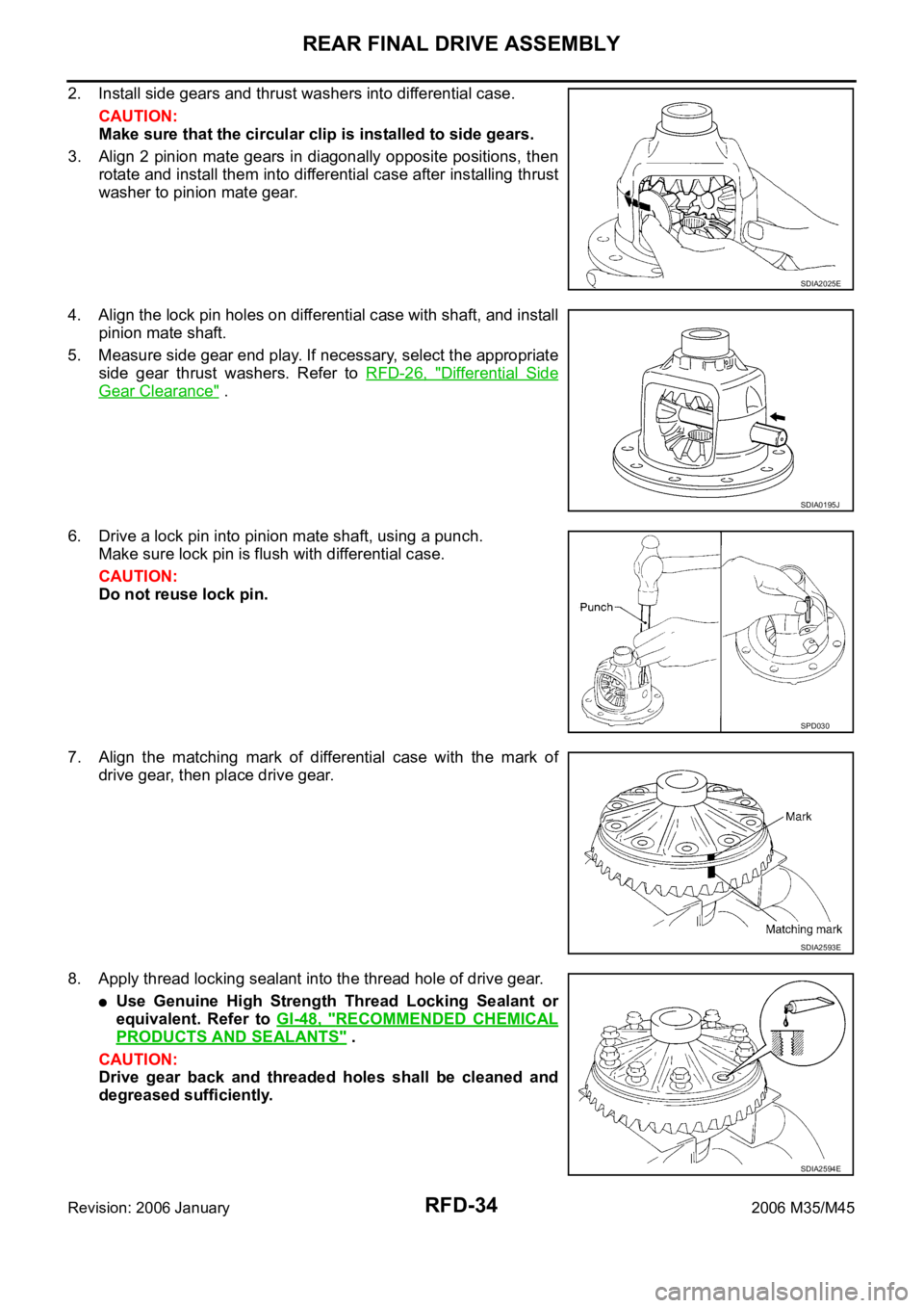
2. Install side gears and thrust washers into differential case.
CAUTION:
Make sure that the circular clip is installed to side gears.
3. Align 2 pinion mate gears in diagonally opposite positions, then
rotate and install them into differential case after installing thrust
washer to pinion mate gear.
4. Align the lock pin holes on differential case with shaft, and install
pinion mate shaft.
5. Measure side gear end play. If necessary, select the appropriate
side gear thrust washers. Refer to RFD-26, "
Differential Side
Gear Clearance" .
6. Drive a lock pin into pinion mate shaft, using a punch.
Make sure lock pin is flush with differential case.
CAUTION:
Do not reuse lock pin.
7. Align the matching mark of differential case with the mark of
drive gear, then place drive gear.
8. Apply thread locking sealant into the thread hole of drive gear.
Use Genuine High Strength Thread Locking Sealant or
equivalent. Refer to GI-48, "
RECOMMENDED CHEMICAL
PRODUCTS AND SEALANTS" .
CAUTION:
Drive gear back and threaded holes shall be cleaned and
degreased sufficiently.
SDIA2025E
SDIA0195J
SPD030
SDIA2593E
SDIA2594E
Page 5083 of 5621

RSU-2
PRECAUTIONS
Revision: 2006 January2006 M35/M45
PRECAUTIONSPFP:00001
PrecautionsNES000J2
When installing rubber bushings, final tightening must be carried out under unladen conditions with tires
on ground. Oil will shorten the life of rubber bushings. Be sure to wipe off any spilled oil.
–Unladen conditions mean that fuel, engine coolant and lubricant are full. Spare tire, jack, hand tools and
mats are in designated positions.
After servicing suspension parts, be sure to check wheel alignment.
Self-lock nuts are not reusable. Always use new ones when installing. Since new self-lock nuts are pre-
oiled, tighten as they are.
Page 5091 of 5621

RSU-10
SHOCK ABSORBER
Revision: 2006 January2006 M35/M45
SHOCK ABSORBERPFP:56210
Removal and InstallationNES000JA
REMOVAL
1. Remove tires from vehicle with a power tool.
2. Set a jack under rear lower link to relieve the coil spring tension.
3. Remove shock absorber lower end bolt with a power tool.
4. Gradually lower the jack to remove it from rear lower link.
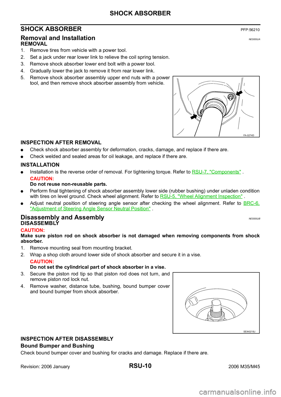
5. Remove shock absorber assembly upper end nuts with a power
tool, and then remove shock absorber assembly from vehicle.
INSPECTION AFTER REMOVAL
Check shock absorber assembly for deformation, cracks, damage, and replace if there are.
Check welded and sealed areas for oil leakage, and replace if there are.
INSTALLATION
Installation is the reverse order of removal. For tightening torque. Refer to RSU-7, "Components" .
CAUTION:
Do not reuse non-reusable parts.
Perform final tightening of shock absorber assembly lower side (rubber bushing) under unladen condition
with tires on level ground. Check wheel alignment. Refer to RSU-5, "
Wheel Alignment Inspection" .
Adjust neutral position of steering angle sensor after checking the wheel alignment. Refer to BRC-6,
"Adjustment of Steering Angle Sensor Neutral Position" .
Disassembly and AssemblyNES000JB
DISASSEMBLY
CAUTION:
Make sure piston rod on shock absorber is not damaged when removing components from shock
absorber.
1. Remove mounting seal from mounting bracket.
2. Wrap a shop cloth around lower side of shock absorber and secure it in a vise.
CAUTION:
Do not set the cylindrical part of shock absorber in a vise.
3. Secure the piston rod tip so that piston rod does not turn, and
remove piston rod lock nut.
4. Remove washer, distance tube, bushing, bound bumper cover
and bound bumper from shock absorber.
INSPECTION AFTER DISASSEMBLY
Bound Bumper and Bushing
Check bound bumper cover and bushing for cracks and damage. Replace if there are.
FA-0274D
SEIA0218J
Page 5102 of 5621

PRE-CRASH SEAT BELT
SB-3
C
D
E
F
G
I
J
K
L
MA
B
SB
Revision: 2006 January2006 M35/M45
PRE-CRASH SEAT BELTPFP:98845
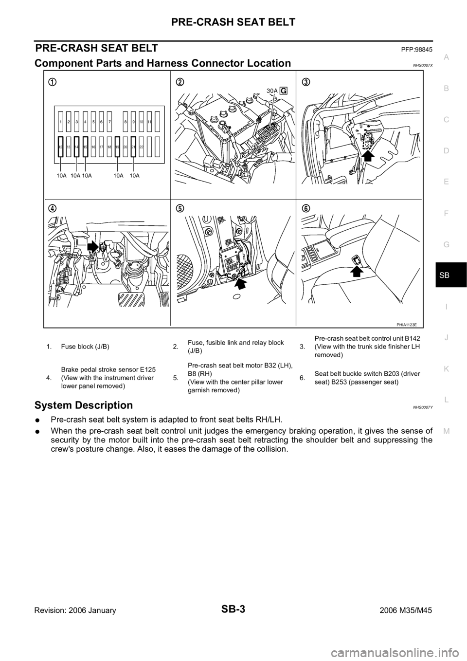
Component Parts and Harness Connector LocationNHS0007X
System DescriptionNHS0007Y
Pre-crash seat belt system is adapted to front seat belts RH/LH.
When the pre-crash seat belt control unit judges the emergency braking operation, it gives the sense of
security by the motor built into the pre-crash seat belt retracting the shoulder belt and suppressing the
crew's posture change. Also, it eases the damage of the collision.
PHIA1123E
1. Fuse block (J/B) 2.Fuse, fusible link and relay block
(J/B)3.Pre-crash seat belt control unit B142
(View with the trunk side finisher LH
removed)
4.Brake pedal stroke sensor E125
(View with the instrument driver
lower panel removed)5.Pre-crash seat belt motor B32 (LH),
B8 (RH)
(View with the center pillar lower
garnish removed)6.Seat belt buckle switch B203 (driver
seat) B253 (passenger seat)
Page 5116 of 5621
![INFINITI M35 2006 Factory Service Manual PRE-CRASH SEAT BELT
SB-17
C
D
E
F
G
I
J
K
L
MA
B
SB
Revision: 2006 January2006 M35/M45
Ignition Power Supply Circuit CheckNHS00089
1. CHECK FUSE
Check 10A fuse [No.15, located in fuse block (J/B)].
NO INFINITI M35 2006 Factory Service Manual PRE-CRASH SEAT BELT
SB-17
C
D
E
F
G
I
J
K
L
MA
B
SB
Revision: 2006 January2006 M35/M45
Ignition Power Supply Circuit CheckNHS00089
1. CHECK FUSE
Check 10A fuse [No.15, located in fuse block (J/B)].
NO](/manual-img/42/57023/w960_57023-5115.png)
PRE-CRASH SEAT BELT
SB-17
C
D
E
F
G
I
J
K
L
MA
B
SB
Revision: 2006 January2006 M35/M45
Ignition Power Supply Circuit CheckNHS00089
1. CHECK FUSE
Check 10A fuse [No.15, located in fuse block (J/B)].
NOTE:
Refer to SB-3, "
Component Parts and Harness Connector Location" .
OK or NG
OK >> GO TO 2.
NG >> If fuse is blown out, be sure to eliminate cause of malfunction before installing new fuse. Refer to
PG-3, "
POWER SUPPLY ROUTING CIRCUIT" .
2. CHECK IGNITION POWER SUPPLY CIRCUIT
1. Disconnect pre-crash seat belt control unit connector.
2. Turn ignition switch ON.
3. Check voltage between pre-crash seat belt control unit harness
connector and ground.
OK or NG
OK >> Ignition power supply circuit is OK.
NG >> Check pre-crash seat belt control unit ignition power supply circuit harness.
Motor Power Supply and Ground Circuit Check [B2454]NHS0008A
1. CHECK FUSE
Check 30A fusible link (letter G , located in the fuse and fusible link box).
NOTE:
Refer to SB-3, "
Component Parts and Harness Connector Location" .
OK or NG
OK >> GO TO 2.
NG >> If fuse is blown out, be sure to eliminate cause of malfunction before installing new fuse. Refer to
PG-3, "
POWER SUPPLY ROUTING CIRCUIT" .
Terminal
Voltage (V)
(Approx.) (+)
(–) Pre-crash seat
belt control unit
connectorTerminal
B142 13 Ground Battery voltage
PHIA1126E
Page 5130 of 5621

SEAT BELTS
SB-31
C
D
E
F
G
I
J
K
L
MA
B
SB
Revision: 2006 January2006 M35/M45
2. Remove the shoulder anchor.
Remove the center pillar lower and upper garnishes, refer to EI-37, "BODY SIDE TRIM" .
Remove the fixing anchor nut of the shoulder anchor.
3. Remove the seat bert assembly.
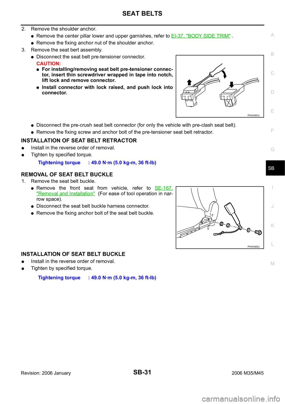
Disconnect the seat belt pre-tensioner connector.
CAUTION:
For installing/removing seat belt pre-tensioner connec-
tor, insert thin screwdriver wrapped in tape into notch,
lift lock and remove connector.
Install connector with lock raised, and push lock into
connector.
Disconnect the pre-crush seat belt connector (for only the vehicle with pre-clash seat belt).
Remove the fixing screw and anchor bolt of the pre-tensioner seat belt retractor.
INSTALLATION OF SEAT BELT RETRACTOR
Install in the reverse order of removal.
Tighten by specified torque.
REMOVAL OF SEAT BELT BUCKLE
1. Remove the seat belt buckle.
Remove the front seat from vehicle, refer to SE-167,
"Removal and Installation" (For ease of tool operation in nar-
row space).
Disconnect the seat belt buckle harness connector.
Remove the fixing anchor bolt of the seat belt buckle.
INSTALLATION OF SEAT BELT BUCKLE
Install in the reverse order of removal.
Tighten by specified torque.
PHIA0953J
Tightening torque : 49.0 Nꞏm (5.0 kg-m, 36 ft-lb)
PHIA0926J
Tightening torque : 49.0 Nꞏm (5.0 kg-m, 36 ft-lb)
Page 5133 of 5621

SB-34
SEAT BELTS
Revision: 2006 January2006 M35/M45
NOTE:
Apply the tape so that there is no looseness or wrinkling.
6. Remove the clip fixing the seat belt and check that the webbing returns smoothly.
6. Repeat steps above as necessary to check the other seat belts.
SEAT BELT RETRACTOR ON-VEHICLE CHECK
Emergency Locking Retractors (ELR) and Automatic Locking Retractors (ALR)
NOTE:
All seat belt retractors are of the Emergency Locking Retractors (ELR) type. In an emergency (sudden stop)
the retractor will lock and prevent the webbing from extending any further. All 3-point type seat belt retractors
except the driver's seat belt also have an Automatic Locking Retractors (ALR) mode. The ALR mode (also
called child restraint mode) is used when installing child seats. The ALR mode is activated when the seat belt
is fully extended. When the webbing is then retracted partially, the ALR mode automatically locks the seat belt
in a specific position so the webbing cannot be extended any further. To cancel the ALR mode, allow the seat
belt to fully wind back into the retractor.
Check the seat belt retractors using the following test(s) to determine if a retractor assembly is operating prop-
erly.
ELR Function Stationary Check
Grasp the shoulder webbing and pull forward quickly. The retractor should lock and prevent the belt from
extending further.
ALR Function Stationary Check
1. Pull out entire length of seat belt from retractor until a click is heard.
2. Retract the webbing partially. A clicking noise should be heard as the webbing retracts indicating that the
retractor is in the Automatic Locking Retractors (ALR) mode.
3. Grasp the seat belt and try to pull out the retractor. The webbing must lock and not extend any further. If
NG, replace the retractor assembly.
4. Allow the entire length of the webbing to retract to cancel the automatic locking mode.
ELR Function Moving Check
WAR NING :
Perform the following test in a safe, open area clear of other vehicles and obstructions (for example, a
large, empty parking lot). Road surface must be paved and dry. DO NOT perform the following test on
wet or gravel roads or on public streets and highways. This could result in an accident and serious
personal injury. The driver and passenger must be prepared to brace themselves in the event the
retractor does not lock.
1. Fasten driver's seat belt. Buckle a passenger into the seat for the belt that is to be tested.
2. Proceed to the designated safe area.
3. Drive the vehicle at approximately 16 km/h (10 MPH). Notify any passengers of a pending sudden stop
and the driver and passenger must be prepared to brace themselves in the event the retractor does not
lock, apply brakes firmly and make a very hard stop.
During stop, seat belts should lock and not be extended. If the seat belt retractor assembly does not lock, per-
form the retractor off-vehicle check.
Page 5147 of 5621

SC-10
STARTING SYSTEM
Revision: 2006 January2006 M35/M45
STARTING SYSTEM PFP:00011
System Description NKS003NI
Power is supplied at all times
through 15A fuse (No. 78, located in the IPDM E/R)
to CPU of IPDM E/R,
through 15A fuse (No. 71, located in the IPDM E/R)
to CPU of IPDM E/R.
Ground is supplied
to IPDM E/R terminals 38 and 51
from grounds E22 and E43.
When the selector lever in the P or N position, power is supplied
from TCM, and through A/T assembly terminal 9
to IPDM E/R terminal 53.
And then provided that IPDM E/R receives a starter relay ON signal with CAN communication, starter relay is
energized.
With the ignition switch in the START position, power is supplied
through IPDM E/R terminal 3
to starter motor terminal 1.
The starter motor plunger closes and provides a closed circuit between the battery and starter motor. The
starter motor is grounded to the engine block. With power and ground supplied, cranking occurs and the
engine starts.