Page 5224 of 5621
AUTOMATIC DRIVE POSITIONER
SE-43
C
D
E
F
G
H
J
K
L
MA
B
SE
Revision: 2006 January2006 M35/M45
2. CHECK GROUND CIRCUIT
1. Turn ignition switch OFF.
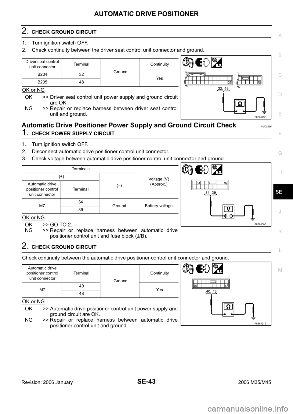
2. Check continuity between the driver seat control unit connector and ground.
OK or NG
OK >> Driver seat control unit power supply and ground circuit
are OK.
NG >> Repair or replace harness between driver seat control
unit and ground.
Automatic Drive Positioner Power Supply and Ground Circuit CheckNIS00266
1. CHECK POWER SUPPLY CIRCUIT
1. Turn ignition switch OFF.
2. Disconnect automatic drive positioner control unit connector.
3. Check voltage between automatic drive positioner control unit connector and ground.
OK or NG
OK >> GO TO 2.
NG >> Repair or replace harness between automatic drive
positioner control unit and fuse block (J/B).
2. CHECK GROUND CIRCUIT
Check continuity between the automatic drive positioner control unit connector and ground.
OK or NG
OK >> Automatic drive positioner control unit power supply and
ground circuit are OK.
NG >> Repair or replace harness between automatic drive
positioner control unit and ground.
Driver seat control
unit connectorTerminal
GroundContinuity
B204 32
Ye s
B205 48
PIIB6129E
Terminals
Voltage (V)
(Approx.) (+)
(–) Automatic drive
positioner control
unit connectorTerminal
M734
Ground Battery voltage
39
PIIB6130E
Automatic drive
positioner control
unit connectorTerminal
GroundContinuity
M740
Ye s
48
PIIB6131E
Page 5263 of 5621
SE-82
AUTOMATIC DRIVE POSITIONER
Revision: 2006 January2006 M35/M45
2. CHECK SEAT MEMORY INDICATOR LAMP POWER SYUPPLY CIRCUIT
1. Turn ignition switch OFF.
2. Disconnect seat memory switch connector.
3. Check voltage between seat memory switch connector and
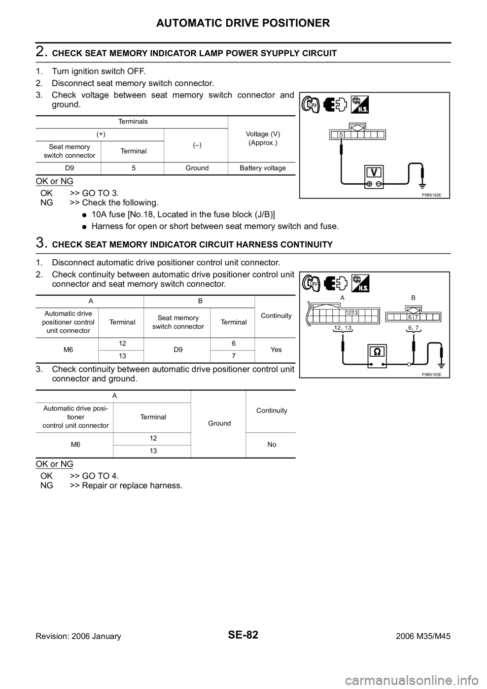
ground.
OK or NG
OK >> GO TO 3.
NG >> Check the following.
10A fuse [No.18, Located in the fuse block (J/B)]
Harness for open or short between seat memory switch and fuse.
3. CHECK SEAT MEMORY INDICATOR CIRCUIT HARNESS CONTINUITY
1. Disconnect automatic drive positioner control unit connector.
2. Check continuity between automatic drive positioner control unit
connector and seat memory switch connector.
3. Check continuity between automatic drive positioner control unit
connector and ground.
OK or NG
OK >> GO TO 4.
NG >> Repair or replace harness.
Terminals
Voltage (V)
(Approx.) (+)
(–)
Seat memory
switch connectorTerminal
D9 5 Ground Battery voltage
PIIB6192E
AB
Continuity Automatic drive
positioner control
unit connectorTe r m i n a lSeat memory
switch connectorTerminal
M612
D96
Ye s
13 7
A
GroundContinuity Automatic drive posi-
tioner
control unit connectorTerminal
M612
No
13
PIIB6193E
Page 5270 of 5621
AUTOMATIC DRIVE POSITIONER
SE-89
C
D
E
F
G
H
J
K
L
MA
B
SE
Revision: 2006 January2006 M35/M45
OK or NG
OK >> Replace driver seat control unit.
NG >> Replace automatic drive positioner control unit.
Lumber Support Circuit CheckNIS0026Y
1. CHECK LUMBER SUPPORT SWITCH
1. Turn ignition switch OFF.
2. Disconnect lumber support switch connector.
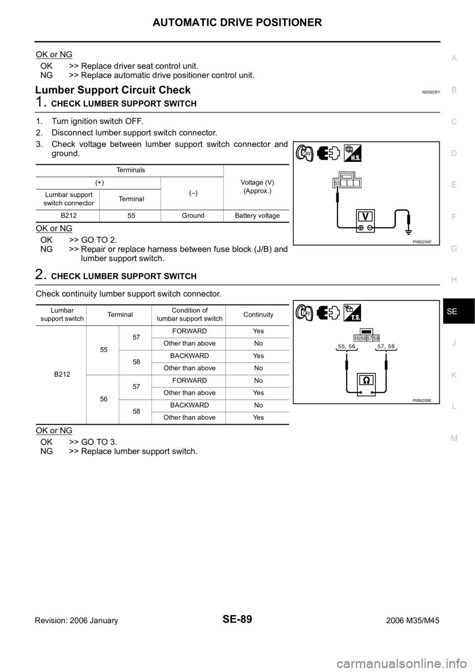
3. Check voltage between lumber support switch connector and
ground.
OK or NG
OK >> GO TO 2.
NG >> Repair or replace harness between fuse block (J/B) and
lumber support switch.
2. CHECK LUMBER SUPPORT SWITCH
Check continuity lumber support switch connector.
OK or NG
OK >> GO TO 3.
NG >> Replace lumber support switch.
Terminals
Voltage (V)
(Approx.) (+)
(–)
Lumbar support
switch connectorTerminal
B212 55 Ground Battery voltage
PIIB6204E
Lumbar
support switchTerminalCondition of
lumbar support switchContinuity
B2125557FORWARD Yes
Other than above No
58BACKWARD Yes
Other than above No
5657FORWARD No
Other than above Yes
58BACKWARD No
Other than above Yes
PIIB6205E
Page 5272 of 5621
POWER SEAT(PASSENGER SIDE)
SE-91
C
D
E
F
G
H
J
K
L
MA
B
SE
Revision: 2006 January2006 M35/M45
POWER SEAT(PASSENGER SIDE)PFP:87050
Component Parts and Harness Connector LocationNIS0026Z
PIIB5888E
1. Fuse block (J/B) 2.Fuse, fusible link and relay block (J/
B)3.BCM M2
(View with the glove box cover
removed)
4.Power seat switch B255
a: Reclining switch
b: Sliding and lifting switch5.a: Sliding motor M264
b: Lifting motor M2666. Reclining motor M263
Page 5276 of 5621
POWER SEAT(REAR)
SE-95
C
D
E
F
G
H
J
K
L
MA
B
SE
Revision: 2006 January2006 M35/M45
POWER SEAT(REAR)PFP:88010
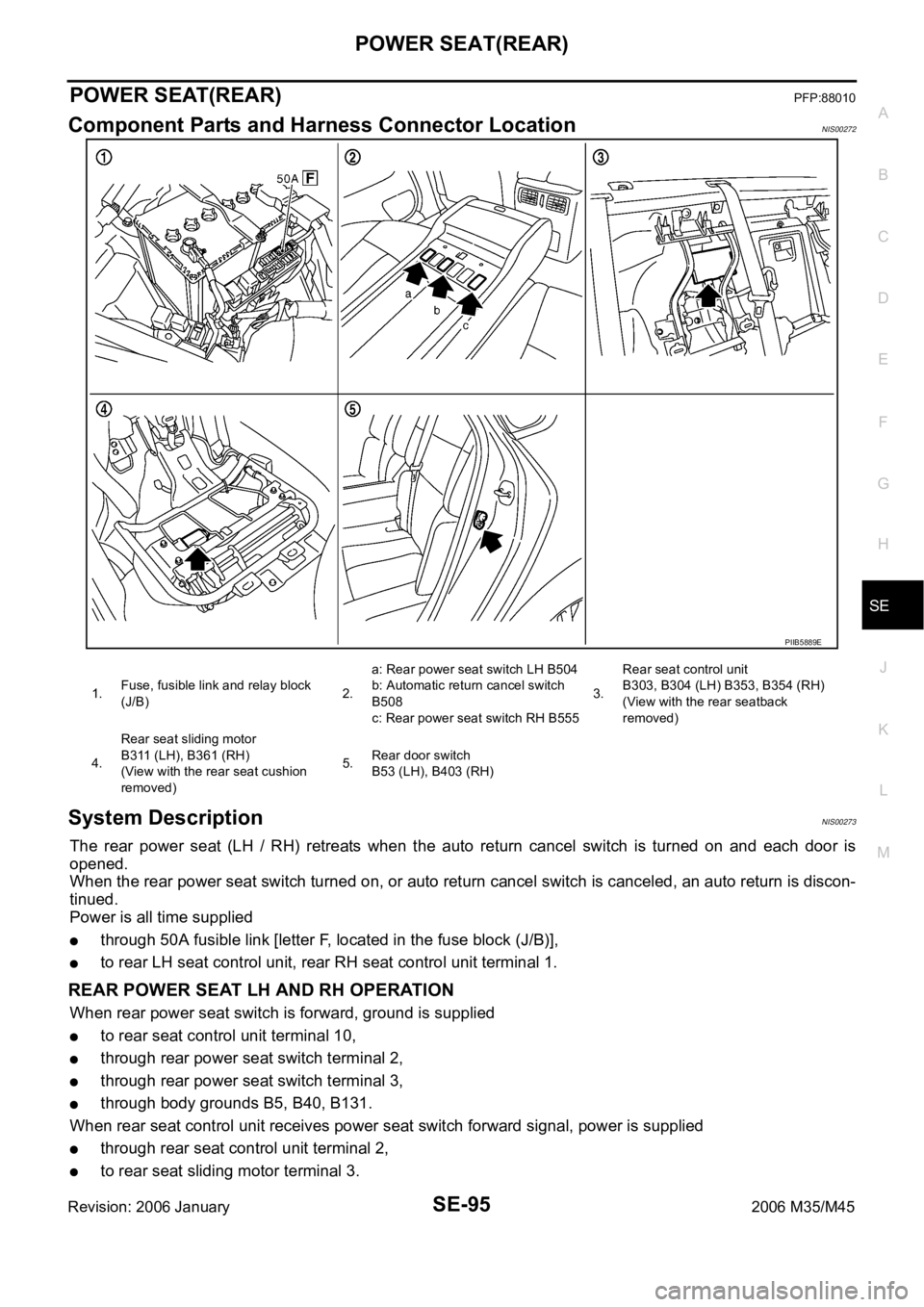
Component Parts and Harness Connector LocationNIS00272
System DescriptionNIS00273
The rear power seat (LH / RH) retreats when the auto return cancel switch is turned on and each door is
opened.
When the rear power seat switch turned on, or auto return cancel switch is canceled, an auto return is discon-
tinued.
Power is all time supplied
through 50A fusible link [letter F, located in the fuse block (J/B)],
to rear LH seat control unit, rear RH seat control unit terminal 1.
REAR POWER SEAT LH AND RH OPERATION
When rear power seat switch is forward, ground is supplied
to rear seat control unit terminal 10,
through rear power seat switch terminal 2,
through rear power seat switch terminal 3,
through body grounds B5, B40, B131.
When rear seat control unit receives power seat switch forward signal, power is supplied
through rear seat control unit terminal 2,
to rear seat sliding motor terminal 3.
PIIB5889E
1.Fuse, fusible link and relay block
(J/B)2.a: Rear power seat switch LH B504
b: Automatic return cancel switch
B508
c: Rear power seat switch RH B5553.Rear seat control unit
B303, B304 (LH) B353, B354 (RH)
(View with the rear seatback
removed)
4.Rear seat sliding motor
B311 (LH), B361 (RH)
(View with the rear seat cushion
removed)5.Rear door switch
B53 (LH), B403 (RH)
Page 5294 of 5621
CLIMATE CONTROLLED SEAT
SE-113
C
D
E
F
G
H
J
K
L
MA
B
SE
Revision: 2006 January2006 M35/M45
CLIMATE CONTROLLED SEATPFP:870U6
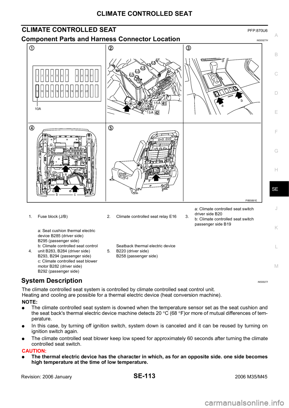
Component Parts and Harness Connector LocationNIS0027H
System DescriptionNIS0027I
The climate controlled seat system is controlled by climate controlled seat control unit.
Heating and cooling are possible for a thermal electric device (heat conversion machine).
NOTE:
The climate controlled seat system is downed when the temperature sensor set as the seat cushion and
the seat back's thermal electric device machine detects 20
C (68 F)or more of mutual differences of tem-
perature.
In this case, by turning off ignition switch, system down is canceled and it can be reused by turning on
ignition switch again.
The climate controlled seat blower keep low speed for approximately 60 seconds after turning the climate
controlled seat switch.
CAUTION:
The thermal electric device has the character in which, as for an opposite side. one side becomes
high temperature at the time of low temperature.
PIIB5891E
1. Fuse block (J/B) 2. Climate controlled seat relay E16 3.a: Climate controlled seat switch
driver side B20
b: Climate controlled seat switch
passenger side B19
4.a: Seat cushion thermal electric
device B285 (driver side)
B295 (passenger side)
b: Climate controlled seat control
unit B283, B284 (driver side)
B293, B294 (passenger side)
c: Climate controlled seat blower
motor B282 (driver side)
B292 (passenger side)5.Seatback thermal electric device
B220 (driver side)
B258 (passenger side)
Page 5295 of 5621

SE-114
CLIMATE CONTROLLED SEAT
Revision: 2006 January2006 M35/M45
At the time of work, please turn OFF a switch, and carry it out after checking that the thermal elec-
tric device has got cold.
Power is at all times supplied
through 15A fuse [No. 41 located in the fuse fusible link and relay unit]
to climate controlled seat relay terminals 5.
through 15A fuse [No. 42 located in the fuse fusible link and relay unit]
to climate controlled seat relay terminals 7.
When the ignition switch turned to ON or START position,
Power is supplied
through 10A fuse [No. 12, located in the fuse block (J/B)]
to climate controlled seat relay terminal 2.
Then ground is supplied
to climate controlled seat relay terminal 1,
through body grounds E22 and E43.
Then climate controlled seat relay is energized.
When climate controlled seat relay is turned to ON,
Power is supplied,
through climate controlled seat relay terminal 3,
to climate controlled seat control unit (passenger side) terminal 2 and 4.
through climate controlled seat relay terminal 6,
to climate controlled seat control unit (driver side) terminal 2 and 4.
When climate controlled switch select HEAT, ground is supplied
through climate controlled seat switch terminal 1 and 3,
to climate controlled seat control unit terminal 10.
Then, the climate controlled seat control unit receives climate controlled seat switch HEAT signal.
When climate controlled seat switch select COOL, ground is supplied
through climate controlled seat switch terminal 1 and 2,
to climate controlled seat control unit terminal 20,
Then, the climate controlled seat control unit receives climate controlled switch COOL signal.
When blower motor rotates, signal is transmitted
to climate controlled seat control unit terminal 18,
through climate controlled seat blower motor terminal 1.
This is climate controlled seat blower motor tachometer signal.
When climate controlled seat control unit receives climate controlled seat switch signal and tachometer signal,
Power is supplied
to climate controlled seat blower motor terminal 4,
through climate controlled seat control unit terminal 17.
This is blower motor revolution control signal.
When blower motor receivers blower motor revolution control signal,
Power is supplied
through climate controlled seat control unit terminal 14,
to climate controlled seat blower motor terminal 2.
When number of rotations correspond signal,
Ground is supplied
to climate controlled seat blower motor terminal 3,
through climate controlled seat control unit terminal 7,
through climate controlled seat control unit terminal 3,
through body grounds B5, B40 and B131.
Then motor revolution is controlled.
When the ignition switch turned to ON or START position,
Power is supplied
Page 5307 of 5621
SE-126
CLIMATE CONTROLLED SEAT
Revision: 2006 January2006 M35/M45
Climate Controlled Seat Control Unit Power Supply Circuit CheckNIS0027P
1. CHECK FUSE
Check 10A fuse [No. 12, located in fuse block (J/B)]
NOTE:
Refer to SE-113, "
Component Parts and Harness Connector Location" .
OK or NG
OK >> GO TO 2.
NG >> If fuse is blown, be sure to eliminate cause of malfunction before installing new fuse, refer to PG-
3, "POWER SUPPLY ROUTING CIRCUIT" .
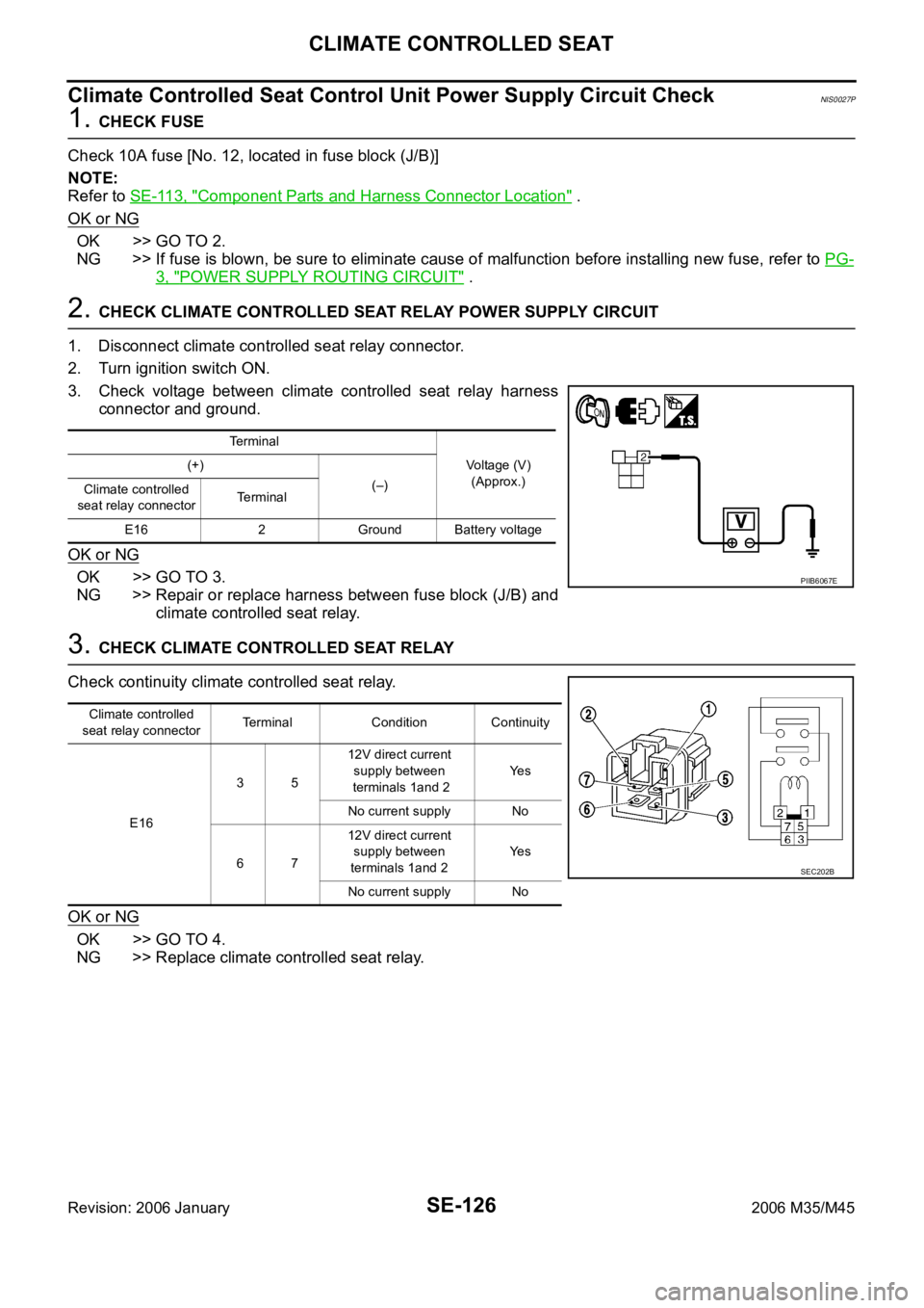
2. CHECK CLIMATE CONTROLLED SEAT RELAY POWER SUPPLY CIRCUIT
1. Disconnect climate controlled seat relay connector.
2. Turn ignition switch ON.
3. Check voltage between climate controlled seat relay harness
connector and ground.
OK or NG
OK >> GO TO 3.
NG >> Repair or replace harness between fuse block (J/B) and
climate controlled seat relay.
3. CHECK CLIMATE CONTROLLED SEAT RELAY
Check continuity climate controlled seat relay.
OK or NG
OK >> GO TO 4.
NG >> Replace climate controlled seat relay.
Terminal
Voltage (V)
(Approx.) (+)
(–)
Climate controlled
seat relay connectorTerminal
E16 2 Ground Battery voltage
PIIB6067E
Climate controlled
seat relay connectorTerminal Condition Continuity
E163512V direct current
supply between
terminals 1and 2Ye s
No current supply No
6712V direct current
supply between
terminals 1and 2Ye s
No current supply No
SEC202B