Page 5243 of 5621
SE-62
AUTOMATIC DRIVE POSITIONER
Revision: 2006 January2006 M35/M45
Tilt Sensor Circuit CheckNIS0026I
1. CHECK TILT SENSOR
With CONSULT-II
With “TILT SEN” on the DATA MONITOR, operate the tilt switch to make sure voltage changes.
Without CONSULT-II
1. Turn ignition switch OFF.
2. Check voltage between automatic drive positioner control unit connector and ground.
OK or NG
OK >> Tilt sensor circuit is OK.
NG >> GO TO 2.
Monitor item
[OPERATION or UNIT]Contents
TILT SEN “V”The tilt position (voltage) judged from the tilt sensor sig-
nal is displayed.
PIIA0295E
Automatic
drive posi-
tioner con-
trol unit
connectorTerminals
ConditionVoltage (V)
(Approx.)
(+) (–)
M6 7 GroundTilt top position 1
Tilt bottom position 3.8
PIIB6161E
Page 5245 of 5621
SE-64
AUTOMATIC DRIVE POSITIONER
Revision: 2006 January2006 M35/M45
2. CHECK DOOR MIRROR LH SENSOR
With CONSULT–II
Check that “VOLTAGE” is displayed on “MIR/SE LH R–L, MIR/SE LH U–D" in the DATA MONITOR.
Without CONSULT–II
1. Turn ignition switch to ACC.
2. Check voltage between automatic drive positioner control unit connector and ground.
OK or NG
OK >> Mirror sensor LH circuit is OK.
NG >> GO TO 3.
Monitor item [OPERATION or
UNIT]Contents
MIR/
SEN LH R–L“V”Voltage output from door mirror LH sensor (LH/
RH) is displayed.
MIR/
SEN LH U–D“V”Voltage output from door mirror LH sensor (UP/
DOWN) is displayed.
PIIB6495E
Automatic
drive posi-
tioner con-
trol unit
connectorTerminals
ConditionVoltage (V)
(Approx.)
(+) (–)
M622
GroundMirror motor is
operated LEFT or
RIGHTChanges between
3.5 (close to right edge) –
0.5 (close to left edge)
6Mirror motor is
operated UP or
DOWN Changes between
4.2 (close to peak) –
0.5 (close to valley)
PIIB6163E
Page 5247 of 5621

SE-66
AUTOMATIC DRIVE POSITIONER
Revision: 2006 January2006 M35/M45
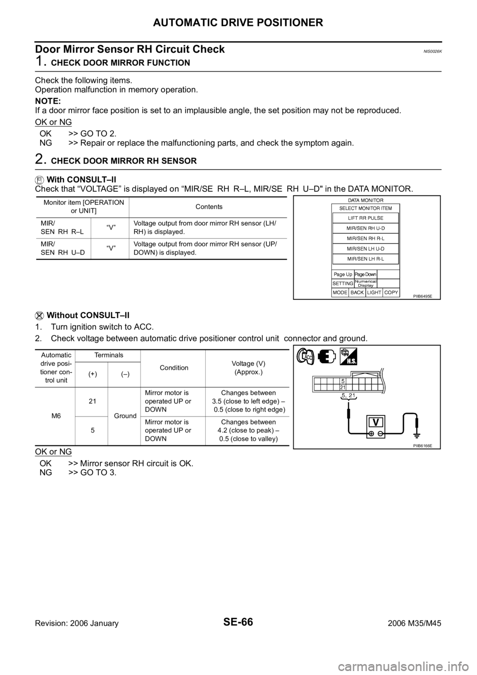
Door Mirror Sensor RH Circuit Check NIS0026K
1. CHECK DOOR MIRROR FUNCTION
Check the following items.
Operation malfunction in memory operation.
NOTE:
If a door mirror face position is set to an implausible angle, the set position may not be reproduced.
OK or NG
OK >> GO TO 2.
NG >> Repair or replace the malfunctioning parts, and check the symptom again.
2. CHECK DOOR MIRROR RH SENSOR
With CONSULT–II
Check that “VOLTAGE” is displayed on “MIR/SE RH R–L, MIR/SE RH U–D" in the DATA MONITOR.
Without CONSULT–II
1. Turn ignition switch to ACC.
2. Check voltage between automatic drive positioner control unit connector and ground.
OK or NG
OK >> Mirror sensor RH circuit is OK.
NG >> GO TO 3.
Monitor item [OPERATION
or UNIT]Contents
MIR/
SEN RH R–L“V”Voltage output from door mirror RH sensor (LH/
RH) is displayed.
MIR/
SEN RH U–D“V”Voltage output from door mirror RH sensor (UP/
DOWN) is displayed.
PIIB6495E
Automatic
drive posi-
tioner con-
trol unitTerminals
ConditionVoltage (V)
(Approx.)
(+) (–)
M621
GroundMirror motor is
operated UP or
DOWNChanges between
3.5 (close to left edge) –
0.5 (close to right edge)
5Mirror motor is
operated UP or
DOWN Changes between
4.2 (close to peak) –
0.5 (close to valley)
PIIB6166E
Page 5249 of 5621
SE-68
AUTOMATIC DRIVE POSITIONER
Revision: 2006 January2006 M35/M45
Sliding Switch Circuit CheckNIS0026L
1. CHECK FUNCTION
With CONSULT-II
With “SLIDE SW-FR, SLIDE SW-RR” on the DATA MONITOR, oper-
ate the sliding switch to check ON/OFF operation.
Without CONSULT-II
1. Turn ignition switch OFF.
2. Check voltage between driver seat control unit connector and
ground.
OK or NG
OK >> Sliding switch circuit is OK.
NG >> GO TO 2.
Monitor item [OPER-
ATION or UNIT]Contents
SLIDE SW–
FR"ON/
OFF"ON / OFF status judged from the sliding switch (FR) sig-
nal is displayed.
SLIDE SW–
RR"ON/
OFF"ON / OFF status judged from the sliding switch (RR) sig-
nal is displayed.
PIIA0313E
Driver seat
control unit
connectorTerminal
ConditionVoltage (V)
(Approx.)
(+) (–)
B20411
GroundSliding switch ON
(BACKWARD oper-
ation)0
Other than above Battery voltage
26Sliding switch ON
(FORWARD opera-
tion)0
Other than above Battery voltage
PIIB6168E
Page 5251 of 5621
SE-70
AUTOMATIC DRIVE POSITIONER
Revision: 2006 January2006 M35/M45
Reclining Switch Circuit CheckNIS0026M
1. CHECK FUNCTION
With CONSULT-II
With “RECLN SW-FR, RECLN SW-RR” on the DATA MONITOR,
operate the reclining switch to check ON/OFF operation.
Without CONSULT-II
1. Turn ignition switch OFF.
2. Check voltage between driver seat control unit connector and
ground.
OK or NG
OK >> Reclining switch circuit is OK.
NG >> GO TO 2.
Monitor item [OPERA-
TION or UNIT]Contents
RECLN SW
–FR“ON/
OFF”ON/OFF status judged from the reclining switch (FR)
signal is displayed.
RECLIN S
W–RR“ON/
OFF”ON/OFF status judged from the reclining switch (RR)
signal is displayed.
PIIA0313E
Driver seat
control unitTe r m i n a l s
ConditionVoltage (V)
(Approx.)
(+) (–)
B20412
GroundReclining switch ON
(BACKWARD oper-
ation)0
Other than above Battery voltage
27Reclining switch ON
(FORWARD opera-
tion)0
Other than above Battery voltage
PIIB6171E
Page 5253 of 5621
SE-72
AUTOMATIC DRIVE POSITIONER
Revision: 2006 January2006 M35/M45
Lifting Switch (Front) Circuit CheckNIS0026N
1. CHECK FUNCTION
With CONSULT-II
With “LIFT FR SW-UP, LIFT FR SW-DN” on the DATA MONITOR,
operate the lifting switch (front) to check ON/OFF operation.
Without CONSULT-II
1. Turn ignition switch OFF.
2. Check voltage between driver seat control unit connector and
ground.
OK or NG
OK >> Lifting switch (front) circuit is OK.
NG >> GO TO 2.
Monitor item [OPERA-
TION or UNIT]Contents
LIFT FR SW–
DN"ON/
OFF"ON / OFF status judged from the FR lifter switch
(DOWN) signal is displayed.
LIFT FR SW–
UP"ON/
OFF"ON / OFF status judged from the FR lifter switch (UP)
signal is displayed.
PIIA0323E
Driver seat
control unit
connectorTerminals
ConditionVoltage (V)
(Approx.)
(+) (–)
B20413
GroundLifting switch (front) ON
(DOWN operation)0
Other than above Battery voltage
28Lifting switch (front) ON
(UP operation)0
Other than above Battery voltage
PIIB6174E
Page 5255 of 5621

SE-74
AUTOMATIC DRIVE POSITIONER
Revision: 2006 January2006 M35/M45
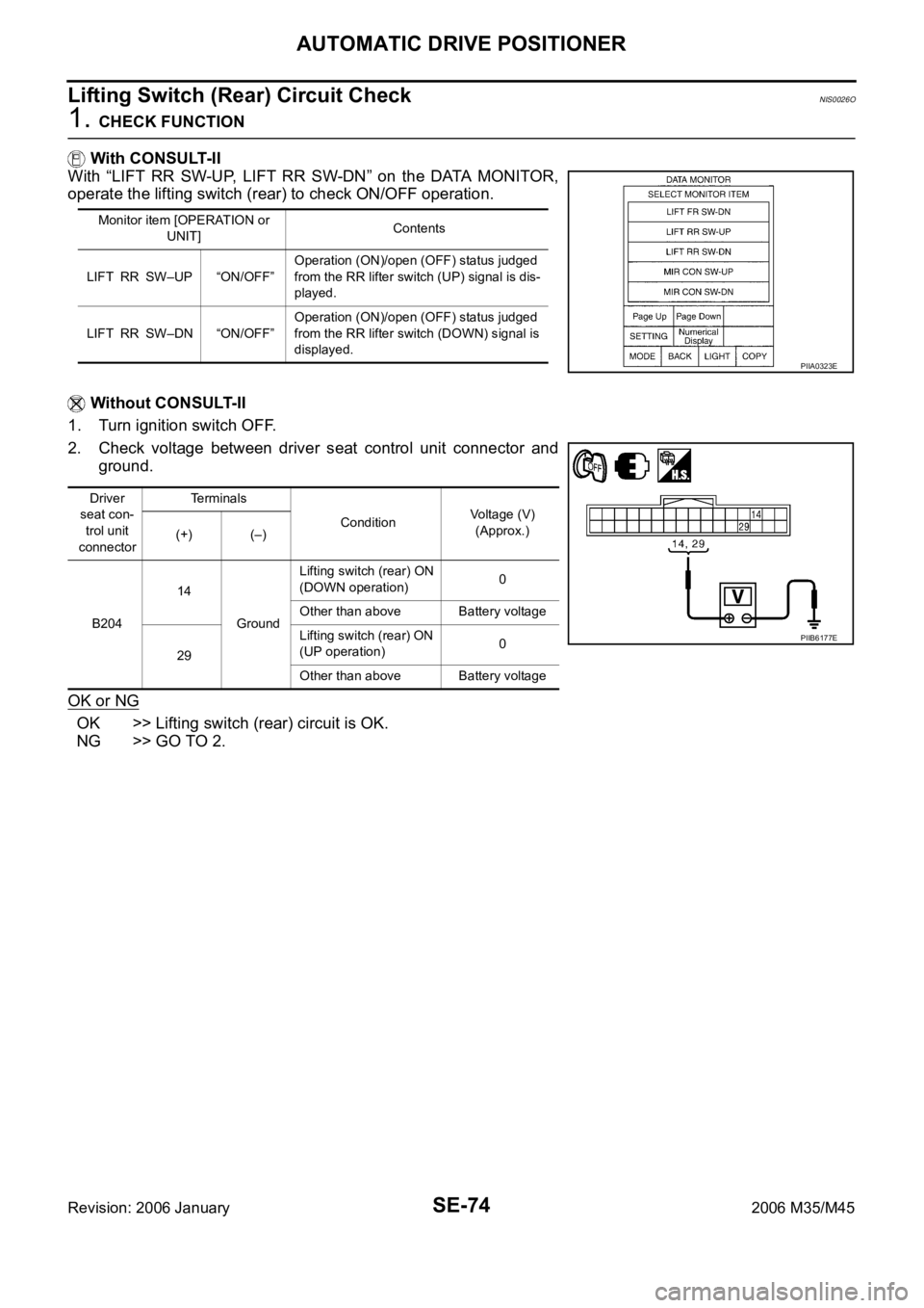
Lifting Switch (Rear) Circuit CheckNIS0026O
1. CHECK FUNCTION
With CONSULT-II
With “LIFT RR SW-UP, LIFT RR SW-DN” on the DATA MONITOR,
operate the lifting switch (rear) to check ON/OFF operation.
Without CONSULT-II
1. Turn ignition switch OFF.
2. Check voltage between driver seat control unit connector and
ground.
OK or NG
OK >> Lifting switch (rear) circuit is OK.
NG >> GO TO 2.
Monitor item [OPERATION or
UNIT]Contents
LIFT RR SW–UP “ON/OFF”Operation (ON)/open (OFF) status judged
from the RR lifter switch (UP) signal is dis-
played.
LIFT RR SW–DN “ON/OFF”Operation (ON)/open (OFF) status judged
from the RR lifter switch (DOWN) signal is
displayed.
PIIA0323E
Driver
seat con-
trol unit
connectorTerminals
ConditionVoltage (V)
(Approx.)
(+) (–)
B20414
GroundLifting switch (rear) ON
(DOWN operation)0
Other than above Battery voltage
29Lifting switch (rear) ON
(UP operation)0
Other than above Battery voltage
PIIB6177E
Page 5257 of 5621
SE-76
AUTOMATIC DRIVE POSITIONER
Revision: 2006 January2006 M35/M45
Telescopic Switch Circuit CheckNIS0026Q
1. CHECK FUNCTION
With CONSULT-II
With “TELESCO SW-FR, TELESCO SW-RR” on the DATA MONITOR, operate the ADP steering switch to
check ON/OFF operation.
Without CONSULT-II
1. Turn ignition switch OFF.
2. Check voltage between automatic drive positioner control unit connector and ground.
OK or NG
OK >> Telescopic switch circuit is OK.
NG >> GO TO 2.
Monitor item
[OPERATION or UNIT]Contents
TELESCO SW-FR “ON/OFF”(ON/OFF) status judged from the telescoping
switch (FR) signal is displayed.
TELESCO SW-RR “ON/OFF” (ON/OFF) status judged from the telescoping
switch (RR) signal is displayed.
PIIA0315E
Automatic
drive posi-
tioner con-
trol unit
connectorTerminals
Telescopic switch conditionVoltage (V)
(Approx.)
(+) (–)
M611
GroundFORWARD 0
Other than above 5
27BACKWARD 0
Other than above 5
PIIB6181E