2006 INFINITI M35 display
[x] Cancel search: displayPage 5388 of 5621

TROUBLE DIAGNOSIS
SRS-27
C
D
E
F
G
I
J
K
L
MA
B
SRS
Revision: 2006 January2006 M35/M45
DIAGNOSTIC PROCEDURE 4 (CONTINUED FROM DIAGNOSTIC PROCEDURE 2)
Inspecting SRS malfunctioning record
1. CONSIDER POSSIBILITY OF NOT ERASING SELF-DIAGNOSTIC RESULT AFTER REPAIRING
Is it the first time for maintenance of SRS?
YES or NO
YES >> Go to SRS-21, "DIAGNOSTIC PROCEDURE 2" .
NO >> Self-diagnostic result “SELF-DIAG [PAST]” (previously stored in the memory) might not be erased
after repair. Go to SRS-25, "
DIAGNOSTIC PROCEDURE 3" .
DIAGNOSTIC PROCEDURE 5
Inspecting SRS intermittent malfunction by using CONSULT-II — Diagnosis mode
CAUTION:
If CONSULT-II is used with no connection of CONSULT-II CONVERTER, malfunctions might be
detected in self-diagnosis depending on control unit which carry out CAN communication.
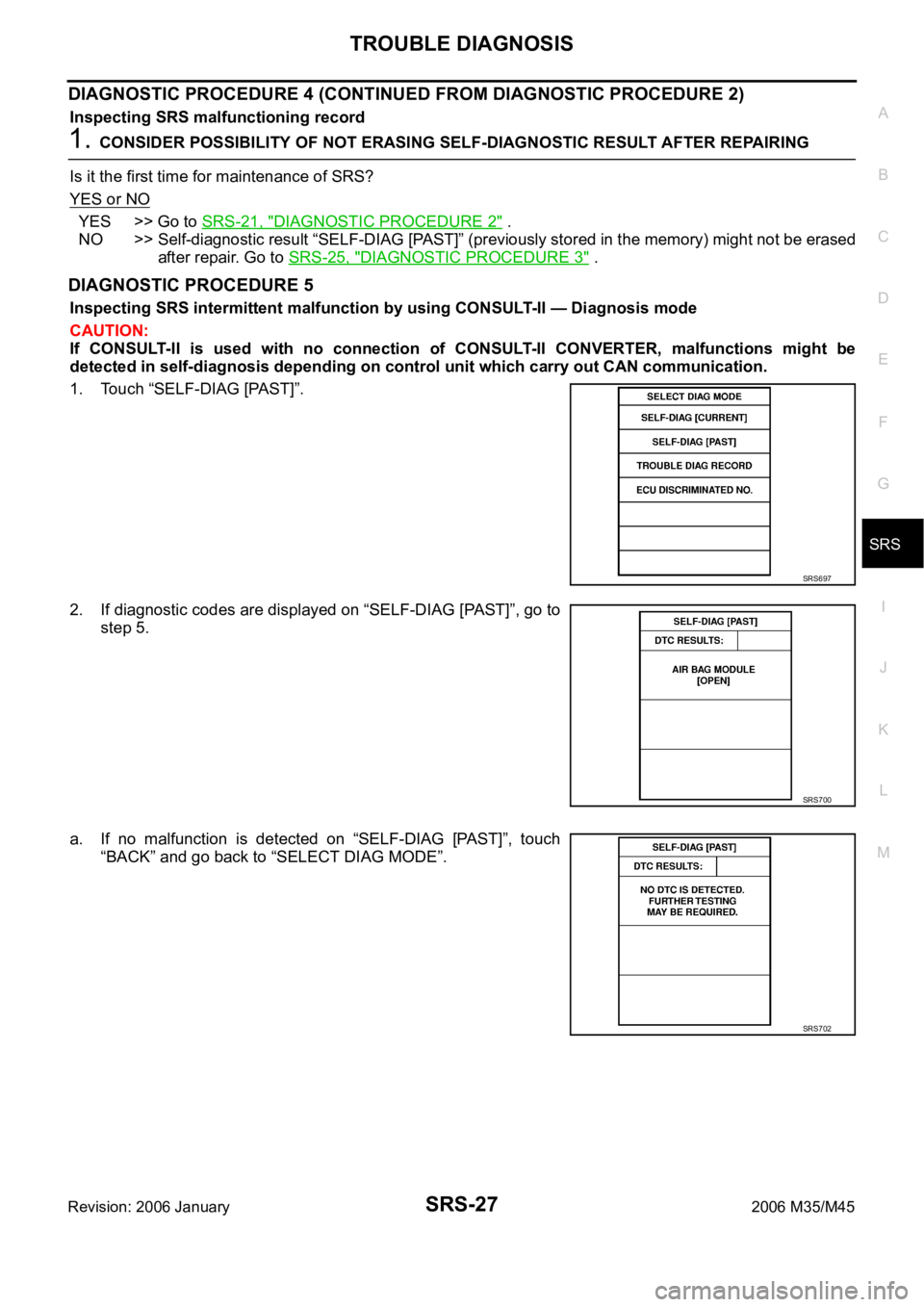
1. Touch “SELF-DIAG [PAST]”.
2. If diagnostic codes are displayed on “SELF-DIAG [PAST]”, go to
step 5.
a. If no malfunction is detected on “SELF-DIAG [PAST]”, touch
“BACK” and go back to “SELECT DIAG MODE”.
SRS697
SRS700
SRS702
Page 5389 of 5621

SRS-28
TROUBLE DIAGNOSIS
Revision: 2006 January2006 M35/M45
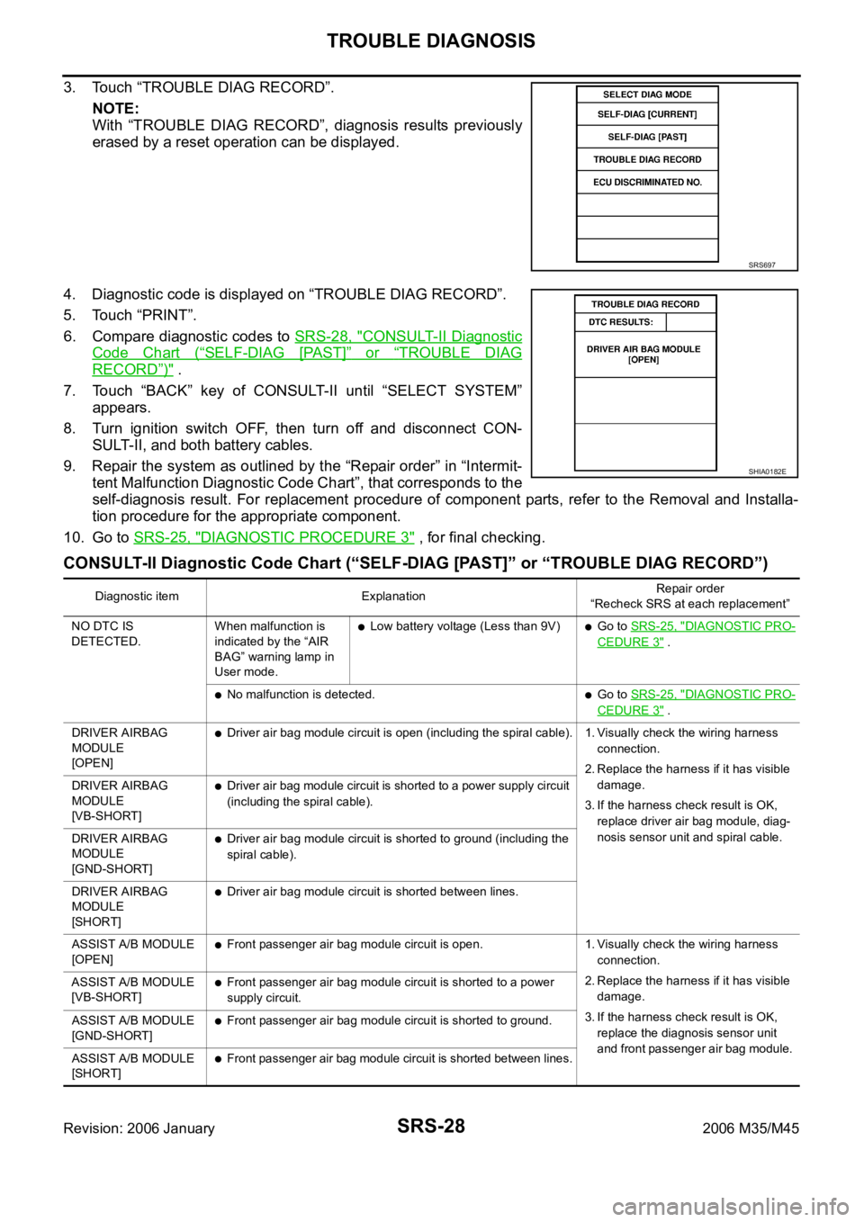
3. Touch “TROUBLE DIAG RECORD”.
NOTE:
With “TROUBLE DIAG RECORD”, diagnosis results previously
erased by a reset operation can be displayed.
4. Diagnostic code is displayed on “TROUBLE DIAG RECORD”.
5. Touch “PRINT”.
6. Compare diagnostic codes to SRS-28, "
CONSULT-II Diagnostic
Code Chart (“SELF-DIAG [PAST]” or “TROUBLE DIAG
RECORD”)" .
7. Touch “BACK” key of CONSULT-II until “SELECT SYSTEM”
appears.
8. Turn ignition switch OFF, then turn off and disconnect CON-
SULT-II, and both battery cables.
9. Repair the system as outlined by the “Repair order” in “Intermit-
tent Malfunction Diagnostic Code Chart”, that corresponds to the
self-diagnosis result. For replacement procedure of component parts, refer to the Removal and Installa-
tion procedure for the appropriate component.
10. Go to SRS-25, "
DIAGNOSTIC PROCEDURE 3" , for final checking.
CONSULT-II Diagnostic Code Chart (“SELF-DIAG [PAST]” or “TROUBLE DIAG RECORD”)
SRS697
SHIA0182E
Diagnostic item ExplanationRepair order
“Recheck SRS at each replacement”
NO DTC IS
DETECTED.When malfunction is
indicated by the “AIR
BAG” warning lamp in
User mode.
Low battery voltage (Less than 9V)Go to SRS-25, "DIAGNOSTIC PRO-
CEDURE 3" .
No malfunction is detected.Go to SRS-25, "DIAGNOSTIC PRO-
CEDURE 3" .
DRIVER AIRBAG
MODULE
[OPEN]
Driver air bag module circuit is open (including the spiral cable). 1. Visually check the wiring harness
connection.
2. Replace the harness if it has visible
damage.
3. If the harness check result is OK,
replace driver air bag module, diag-
nosis sensor unit and spiral cable. DRIVER AIRBAG
MODULE
[VB-SHORT]
Driver air bag module circuit is shorted to a power supply circuit
(including the spiral cable).
DRIVER AIRBAG
MODULE
[GND-SHORT]
Driver air bag module circuit is shorted to ground (including the
spiral cable).
DRIVER AIRBAG
MODULE
[SHORT]
Driver air bag module circuit is shorted between lines.
ASSIST A/B MODULE
[OPEN]
Front passenger air bag module circuit is open. 1. Visually check the wiring harness
connection.
2. Replace the harness if it has visible
damage.
3. If the harness check result is OK,
replace the diagnosis sensor unit
and front passenger air bag module. ASSIST A/B MODULE
[VB-SHORT]
Front passenger air bag module circuit is shorted to a power
supply circuit.
ASSIST A/B MODULE
[GND-SHORT]
Front passenger air bag module circuit is shorted to ground.
ASSIST A/B MODULE
[SHORT]
Front passenger air bag module circuit is shorted between lines.
Page 5397 of 5621

SRS-36
TROUBLE DIAGNOSIS
Revision: 2006 January2006 M35/M45
Trouble Diagnosis: “AIR BAG” Warning Lamp Does Not Turn OFFNHS00099
DIAGNOSTIC PROCEDURE 7
1. CHECK THE DEPLOYMENT OF AIR BAG MODULE
Is air bag module deployed?
YES or NO
YES >> Refer to SRS-50, "COLLISION DIAGNOSIS" .
NO >> GO TO 2.
2. CHECK THE AIR BAG FUSE
Check 10A fuse [No.13, located in fuse block (J/B)].
Refer to PG-3, "
POWER SUPPLY ROUTING CIRCUIT" .
OK or NG
OK >> GO TO 4.
NG >> GO TO 3.
3. CHECK AIR BAG FUSE AGAIN
Replace “AIR BAG” fuse and turn ignition switch ON.
Does the
“AIR BAG” fuse blow again?
YES >> Repair or replace main harness.
NO >>INSPECTION END
4. CHECK DIAGNOSIS SENSOR UNIT
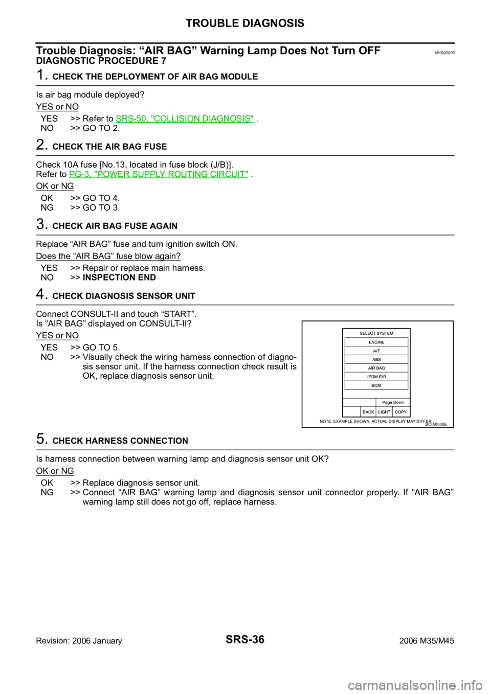
Connect CONSULT-II and touch “START”.
Is “AIR BAG” displayed on CONSULT-II?
YES or NO
YES >> GO TO 5.
NO >> Visually check the wiring harness connection of diagno-
sis sensor unit. If the harness connection check result is
OK, replace diagnosis sensor unit.
5. CHECK HARNESS CONNECTION
Is harness connection between warning lamp and diagnosis sensor unit OK?
OK or NG
OK >> Replace diagnosis sensor unit.
NG >> Connect “AIR BAG” warning lamp and diagnosis sensor unit connector properly. If “AIR BAG”
warning lamp still does not go off, replace harness.
BCIA0030E
Page 5416 of 5621

STC-1
STEERING CONTROL SYSTEM
G STEERING
CONTENTS
C
D
E
F
H
I
J
K
L
M
SECTION STC
A
B
STC
Revision: 2006 January2006 M35/M45
STEERING CONTROL SYSTEM
EPS
SYSTEM DESCRIPTION ............................................ 3
Components ............................................................. 3
Components (Models with Rear Active Steer) ......... 3
Electronically Controlled Power Steering System
Function ................................................................... 3
Fail-Safe Function .................................................... 4
FAIL-SAFE INPUT/CANCEL CONDITIONS ......... 4
TROUBLE DIAGNOSIS .............................................. 5
How to Perform Trouble Diagnosis .......................... 5
BASIC CONCEPT ................................................. 5
Component Parts Location ....................................... 5
Wiring Diagram — EPS — ....................................... 6
Control Unit Input/Output Signal Standard ............... 8
STANDARD BY CIRCUIT TESTER AND OSCIL-
LOSCOPE ........................................................
..... 8
For Fast and Accurate Trouble Diagnosis ................ 9
Basic Inspection ....................................................... 9
POWER SUPPLY CIRCUIT TERMINAL LOOSE-
NESS AND BATTERY .......................................... 9
Inspection: Power Steering Control Unit Power Sup-
ply Circuit and Ground ............................................. 9
Symptom: The Steering Force Does Not Change
Smoothly According to the Vehicle Speed ............. 10
RAS
REAR ACTIVE STEER ............................................. 13
Removal and Installation ........................................ 13
COMPONENTS .................................................. 13
REMOVAL ........................................................
... 13
INSTALLATION ................................................... 13
Disassembly and Assembly ................................... 14
COMPONENTS .................................................. 14
DISASSEMBLY ................................................... 14
INSPECTION AFTER DISASSEMBLY ............... 14
ASSEMBLY ......................................................... 14
Neutral Position Adjustment ................................... 14
SYSTEM DESCRIPTION .......................................... 16
Components ........................................................... 16RAS (Rear Active Steer) Function .......................... 16
Fail-Safe Function .................................................. 17
TROUBLE DIAGNOSIS ............................................ 18
How to Perform Trouble Diagnosis ......................... 18
BASIC CONCEPT ............................................... 18
Component Parts Location ..................................... 19
Schematic ............................................................... 20
Wiring Diagram — RAS — ..................................... 21
Control Unit Input/Output Signal Standard ............. 26
CIRCUIT TESTER REFERENCE VALUE ........... 26
STANDARD BY CONSULT-II .............................. 27
CONSULT-II Function (RAS) .................................. 28
FUNCTION .......................................................
... 28
CONSULT-II SETTING PROCEDURE ................ 28
SELF-DIAG RESULT MODE ............................... 28
DATA MONITOR MODE ...................................... 30
ACTIVE TEST MODE ......................................... 30
RAS CONTROL UNIT PART NUMBER .............. 30
Diagnosis Procedure with Self-Diagnosis Function
(Without CONSULT-II) ............................................ 31
DESCRIPTION .................................................... 31
SELF-DIAGNOSIS PROCEDURE ...................... 31
SELF-DIAGNOSIS DISPLAY .............................. 31
SELF-DIAGNOSIS DISPLAY ITEMS .................. 31
HOW TO ERASE SELF-DIAGNOSIS ................. 31
CAN Communication .............................................. 31
SYSTEM DESCRIPTION .................................... 31
For Fast and Accurate Trouble Diagnosis .............. 32
Basic Inspection ..................................................... 32
BASIC INSPECTION 1: POWER SUPPLY CIR-
CUIT TERMINAL LOOSENESS AND BATTERY ... 32
BASIC INSPECTION 2: RAS WARNING LAMP
INSPECTION ...................................................... 32
BASIC INSPECTION 3: RAS CONTROL UNIT
POWER SUPPLY CIRCUIT AND GROUND CIR-
CUIT INSPECTION ............................................. 32
Trouble Diagnosis Chart ......................................... 33
SELF-DIAGNOSIS .............................................. 33
DIAGNOSIS CHART BY SYMPTOM .................. 34
Inspection 1: RAS Control Unit Malfunction ........... 35
Page 5430 of 5621
![INFINITI M35 2006 Factory Service Manual REAR ACTIVE STEER
STC-15
[RAS]
C
D
E
F
H
I
J
K
L
MA
B
STC
Revision: 2006 January2006 M35/M45
4. Supply 6 V voltage by connecting the four 1.5 V batteries in a
series. Connect them to the RAS motor con INFINITI M35 2006 Factory Service Manual REAR ACTIVE STEER
STC-15
[RAS]
C
D
E
F
H
I
J
K
L
MA
B
STC
Revision: 2006 January2006 M35/M45
4. Supply 6 V voltage by connecting the four 1.5 V batteries in a
series. Connect them to the RAS motor con](/manual-img/42/57023/w960_57023-5429.png)
REAR ACTIVE STEER
STC-15
[RAS]
C
D
E
F
H
I
J
K
L
MA
B
STC
Revision: 2006 January2006 M35/M45
4. Supply 6 V voltage by connecting the four 1.5 V batteries in a
series. Connect them to the RAS motor connector (motor side),
and then operate the motor and adjust the rack in the neutral
position (A).
CAUTION:
Do not supply 12 V voltage (battery, etc) to the RAS motor.
NOTE:
For right stroke, connect positive probe to the RAS motor con-
nector terminal 1. For left stroke, connect it to the terminal 2.
5. Install rear wheel steering angle sensor with O-ring to the RAS
actuator assembly. Temporarily tighten the mounting bolts in the specified torque that the sensor can be
moved by hand.
6. Turn and adjust the rear wheel steering angle sensor so as to make each sensor signal of “DATA MONI-
TOR” mode to the following standard with CONSULT-II.
CAUTION:
During DATA MONITOR mode, “MONITORING ERROR” is displayed. But there is not malfunction
in this procedure.
7. Tighten rear wheel steering angle sensor mounting bolts.
8. Perform “ERASE” with CONSULT-II, and then erase the error memory of rear wheel steering angle sen-
sor. Refer to STC-29, "
How to Erase Self-Diagnostic Results" .
9. Perform CONSULT-II “SELF-DIAG RESULTS” again, and then make sure that there is no malfunction.
Refer to STC-28, "
SELF-DIAG RESULT MODE" . Full stroke (B) : 6.8 - 7.2 mm (0.268 - 0.283 in)
STEERING ANG () L - 0, R - 0, N - 0
RR ST ANG-MAI (V) Approx. 2.4
RR ST ANG-SUB (V) Approx. 2.4
RR ST ANG-VOL (V) Approx. 5.0
SGIA1240E
Page 5442 of 5621
![INFINITI M35 2006 Factory Service Manual TROUBLE DIAGNOSIS
STC-27
[RAS]
C
D
E
F
H
I
J
K
L
MA
B
STC
Revision: 2006 January2006 M35/M45
STANDARD BY CONSULT-II
CAUTION:
The output signal indicates the RAS control unit calculation data. The norm INFINITI M35 2006 Factory Service Manual TROUBLE DIAGNOSIS
STC-27
[RAS]
C
D
E
F
H
I
J
K
L
MA
B
STC
Revision: 2006 January2006 M35/M45
STANDARD BY CONSULT-II
CAUTION:
The output signal indicates the RAS control unit calculation data. The norm](/manual-img/42/57023/w960_57023-5441.png)
TROUBLE DIAGNOSIS
STC-27
[RAS]
C
D
E
F
H
I
J
K
L
MA
B
STC
Revision: 2006 January2006 M35/M45
STANDARD BY CONSULT-II
CAUTION:
The output signal indicates the RAS control unit calculation data. The normal values will be displayed
even in the event that the output circuit (harness) is open.
Monitor itemDATA MONITOR
Malfunction inspection
checklist
Condition Reference values
VHCL SPEED SE (km/h)Ignition switch ON or engine
running Almost in accordance with the speed-
ometer display. It is not a malfunction,
through it might not be corresponding
just after ignition switch is turned ON.STC-38, "
Inspection 4:
Vehicle Speed Signal"
STEERING ANG ()Turning steering wheel clock-
wise or counterclockwise.Displays the angle when the steering
wheel turns from the neutral positionSTC-38, "
Inspection 5:
Steering Angle Signal
Malfunction"
ENGINE SPEED (rpm) Engine runningAlmost in accordance with tachometer
displaySTC-43, "
Inspection 8:
Engine Speed Signal
Malfunction"
POWER STR SOL (A)Accelerate the vehicle from 0
to 100 km/h (0 to 62 MPH)0 km/h (0 MPH): Approx. 1.10 A
100 km/h (62 MPH): Approx. 0.54 ASTC-46, "Diagnosis
Chart by Symptom 2"
RR ST ANG-MAI (V)
Perform the ACTIVE TEST
and stroke the actuator (with
tires off the ground)Neutral: Approx. 2.4 V
Turn steering wheel to right for full
stroke: Approx. 4.4 V
Turn steering wheel to left for full
stroke: Approx. 0.4 VSTC-40, "Inspection 6:
Rear Main Signal and
Rear Sub Signal Mal-
function"RR ST ANG- SUB (V)
RR ST ANG-VOL (V)
Ignition switch ON or engine
runningApprox. 5 VSTC-40, "
Inspection 6:
Rear Main Signal and
Rear Sub Signal Mal-
function"
C/U VOLTAGE (V) Battery voltage (Approx. 12 V)STC-35, "
Inspection 1:
RAS Control Unit Mal-
function"
MOTOR VOLTAGE (V) Battery voltage (Approx. 12V)STC-35, "
Inspection 2:
Motor Power Supply
System"
MOTOR CURRENT (A)Perform the ACTIVE TEST
and stroke the actuator.It is normal when there is the current
output at strokeSTC-35, "
Inspection 2:
Motor Power Supply
System"
MTR CRNT OPE (A)Turning steering wheel clock-
wise or counterclockwise
while ignition switch is ON or
running the engineNeutral (Steering force is zero and
straight-ahead position): Approx. 0 A
The value is changed according to
steering left or right STC-37, "
Inspection 3:
RAS Motor Output
Malfunction"
STOP LAMP SWDepressing or releasing brake
pedalBrake pedal depressed: ONSTC-44, "
Inspection
10: Stop Lamp Switch
Harness"Brake pedal not depressed: OFF
RAS RELAY
Ignition switch ON or engine
runningIgnition switch ON: ONSTC-35, "
Inspection 2:
Motor Power Supply
System"
FAIL SAFE Not activatedSelf-diagnosis and
suspect system
inspection on DATA
MONITOR
WARNING LAMP (ON/OFF)RAS warning lamp ON: ON
RAS warning lamp OFF: OFFWarning lamp circuit
inspection
Page 5443 of 5621
![INFINITI M35 2006 Factory Service Manual STC-28
[RAS]
TROUBLE DIAGNOSIS
Revision: 2006 January2006 M35/M45
CONSULT-II Function (RAS)NGS000EG
FUNCTION
CONSULT-II can display each self-diagnostic item using the diagnostic test modes shown foll INFINITI M35 2006 Factory Service Manual STC-28
[RAS]
TROUBLE DIAGNOSIS
Revision: 2006 January2006 M35/M45
CONSULT-II Function (RAS)NGS000EG
FUNCTION
CONSULT-II can display each self-diagnostic item using the diagnostic test modes shown foll](/manual-img/42/57023/w960_57023-5442.png)
STC-28
[RAS]
TROUBLE DIAGNOSIS
Revision: 2006 January2006 M35/M45
CONSULT-II Function (RAS)NGS000EG
FUNCTION
CONSULT-II can display each self-diagnostic item using the diagnostic test modes shown following.
CONSULT-II SETTING PROCEDURE
Refer to GI-39, "CONSULT-II Start Procedure" .
SELF-DIAG RESULT MODE
Operation Procedure
1. Perform “CONSULT-II Start Procedure”. Refer to GI-39, "CONSULT-II Start Procedure" .
2. Touch “PRINT” to print out the self-diagnostic results if necessary. Check RAS warning lamp if “NO FAIL-
URE” is displayed.
3. Perform the appropriate inspection from the display item list, and repair or replace the malfunctioning
component. Refer to STC-28, "
Display Item List" .
Display Item List
CAUTION:
When malfunctions are detected in several systems, including the “CAN COMM [U1000]” and
“CONTROL_UNIT (CAN) [U1010]”, inspect the CAN communication system.
Mode Function Reference
SELF-DIAG RESULTSReceives self-diagnosis results from RAS control unit and
indicates DTCs.STC-28, "
SELF-DIAG RESULT
MODE"
DATA MONITORReceives input/output signals from RAS control unit and
indicates and stores them to facilitate locating cause of
malfunctions.STC-30, "DATA MONITOR MODE"
CAN DIAG SUPPORT MNTRMonitors transmitting/receiving status of CAN communi-
cation.STC-31, "CAN Communication"
ACTIVE TESTSends command to RAS actuator to change output sig-
nals and check operation of output system.STC-30, "ACTIVE TEST MODE"
ECU PART NUMBER Displays RAS control unit part number.STC-30, "RAS CONTROL UNIT
PART NUMBER"
DTC code Diagnostic item Diagnostic item is detected when... Check items
C1923 STEERING_ANGLE_SEN [NO_CHANGE] (ꞏ a)While driving at 60 km/h (37 MPH)
or more, steering angle does not
change for a while.STC-38
C1924 STEERING_ANGLE_SEN [NO_NEUT_STATE] (ꞏ b)When driving some distance, no
neutral signal (ON signal) is input.STC-38
C1915 RR_ST_ANGLE_SENSOR [MAIN_SIGNAL] (ꞏ a)The main sensor input signal is
malfunctioning for some time
against the sensor power supply
value.STC-40
C1916 RR_ST_ANGLE_SENSOR [SUB_SIGNAL] (ꞏ b)When the main sensor input signal
is 2.4 - 2.6 V, the sub sensor input
signal is malfunctioning for some
time compared to the sensor power
supply value.STC-40
C1917, C1918 RR_ST_ANGLE_SENSOR [OFFSET_SIG1,2] (ꞏ c)An excessive difference has
occurred in the input values of main
sensor and sub sensor.STC-40
C1914 RR_ST_ANGLE_SENSOR [ABNORMAL_VOL] (ꞏ d)Higher or lower value compared to
the standard voltage.STC-40
C1921 MOTOR_OUTPUTNo engine speed is input for a cer-
tain time.STC-43
C1911 MOTOR_VOLTAGE [LOW_VOLTAGE] (ꞏ a)The motor power supply voltage is
lower than ignition power supply
voltage with RAS motor relay ON.STC-35
Page 5445 of 5621
![INFINITI M35 2006 Factory Service Manual STC-30
[RAS]
TROUBLE DIAGNOSIS
Revision: 2006 January2006 M35/M45
DATA MONITOR MODE
Operation Procedure
1. Perform “CONSULT-II Start Procedure”. Refer to GI-39, "CONSULT-II Start Procedure" INFINITI M35 2006 Factory Service Manual STC-30
[RAS]
TROUBLE DIAGNOSIS
Revision: 2006 January2006 M35/M45
DATA MONITOR MODE
Operation Procedure
1. Perform “CONSULT-II Start Procedure”. Refer to GI-39, "CONSULT-II Start Procedure"](/manual-img/42/57023/w960_57023-5444.png)
STC-30
[RAS]
TROUBLE DIAGNOSIS
Revision: 2006 January2006 M35/M45
DATA MONITOR MODE
Operation Procedure
1. Perform “CONSULT-II Start Procedure”. Refer to GI-39, "CONSULT-II Start Procedure" .
2. Touch “DATA MONITOR”.
3. Select from “SELECT MONITOR ITEM”, screen of data monitor is displayed.
NOTE:
When malfunction is detected, CONSULT-II performs REAL-TIME DIAGNOSIS. Also, any malfunction
detected while in this mode will be displayed in real time.
Display Item List
ACTIVE TEST MODE
Operation Procedure
1. Perform “CONSULT-II Start Procedure”. Refer to GI-39, "CONSULT-II Start Procedure" .
2. When turning the steering wheel right or left, the rear wheel turns in the same direction. If the steering
wheel is not turned, the rear wheel turns left and right 5 times.
RAS CONTROL UNIT PART NUMBER
1. Perform “CONSULT-II Start Procedure”. Refer to GI-39, "CONSULT-II Start Procedure" .
2. The part number described on RAS control unit sticker is displayed.
Item (Display or Unit) Remarks
VHCL SPEED SE (km/h) Vehicle speed received via CAN communication is displayed.
STEERING ANG (
) Steering angle received via CAN communication is displayed.
ENGINE SPEED (rpm) Engine speed received via CAN communication is displayed.
POWER STR SOL (A)Power steering solenoid controlling current that RAS control unit outputs is dis-
played.
RR ST ANG_MAI (V) Rear wheel steering angle main sensor output voltage is displayed.
RR ST ANG_SUB (V) Rear wheel angle sub sensor output voltage is displayed.
RR ST ANG_ VOL (V)Voltage supplied from RAS control unit to rear wheel steering angle sensor is
displayed.
C/U VOLTAGE (V) Voltage supplied to RAS control unit is displayed.
MOTOR VOLTAGE (V) Voltage supplied from RAS control unit to RAS motor is displayed.
MOTOR CURRENT (A) RAS motor relay controlling current that RAS control unit outputs is displayed.
MOTOR CRNT OPE (A) Current commanded value to RAS motor is displayed.
RR ANG OPE (
) Angle commanded value to rear wheel steering angle sensor is displayed.
STOP LAMP SW (ON/OFF) Condition of stop lamp switch ON/OFF is displayed.
HICAS RELAY (ON/OFF) RAS motor relay ON/OFF condition is displayed.
FAILSAFE (ON/OFF) Fail-safe ON/OFF condition is displayed.
WARNING LAMP (ON/OFF) RAS warning lamp operating condition is displayed.
STEERING ANG RR ST ANG_MAI RR ST ANG_SUB MOTOR CURRENT
0
(Neutral) 2.4 V 2.4 V No output (Approx. 0 A)
R 90
Approx. 4.4 V Approx. 4.4 V
Output (change)
L 90
Approx. 0.4 V Approx. 0.4 V