2006 INFINITI M35 mirror
[x] Cancel search: mirrorPage 3644 of 5621
IDX-3
A
C
D
E
F
G
H
I
J
K
L B
IDX
ALPHABETICAL INDEX
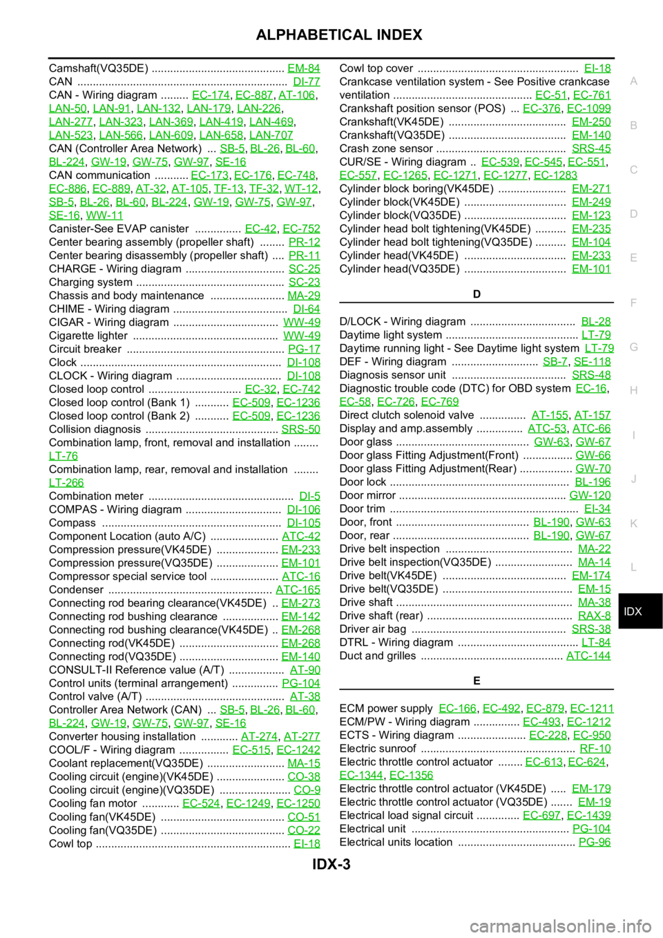
Camshaft(VQ35DE) ........................................... EM-84
CAN .................................................................... DI-77
CAN - Wiring diagram ......... EC-174, EC-887, AT-106,
LAN-50
, LAN-91, LAN-132, LAN-179, LAN-226,
LAN-277
, LAN-323, LAN-369, LAN-419, LAN-469,
LAN-523
, LAN-566, LAN-609, LAN-658, LAN-707
CAN (Controller Area Network) ... SB-5, BL-26, BL-60,
BL-224
, GW-19, GW-75, GW-97, SE-16
CAN communication ........... EC-173, EC-176, EC-748,
EC-886
, EC-889, AT-32, AT-105, TF-13, TF-32, WT-12,
SB-5
, BL-26, BL-60, BL-224, GW-19, GW-75, GW-97,
SE-16
, WW-11
Canister-See EVAP canister ............... EC-42, EC-752
Center bearing assembly (propeller shaft) ........ PR-12
Center bearing disassembly (propeller shaft) .... PR-11
CHARGE - Wiring diagram ................................ SC-25
Charging system ................................................ SC-23
Chassis and body maintenance ........................ MA-29
CHIME - Wiring diagram ..................................... DI-64
CIGAR - Wiring diagram .................................. WW-49
Cigarette lighter ............................................... WW-49
Circuit breaker ................................................... PG-17
Clock ................................................................. DI-108
CLOCK - Wiring diagram .................................. DI-108
Closed loop control .............................. EC-32, EC-742
Closed loop control (Bank 1) ........... EC-509, EC-1236
Closed loop control (Bank 2) ........... EC-509, EC-1236
Collision diagnosis ........................................... SRS-50
Combination lamp, front, removal and installation ........
LT-76
Combination lamp, rear, removal and installation ........
LT-266
Combination meter ............................................... DI-5
COMPAS - Wiring diagram ............................... DI-106
Compass .......................................................... DI-105
Component Location (auto A/C) ...................... ATC-42
Compression pressure(VK45DE) .................... EM-233
Compression pressure(VQ35DE) .................... EM-101
Compressor special service tool ...................... ATC-16
Condenser ..................................................... ATC-165
Connecting rod bearing clearance(VK45DE) .. EM-273
Connecting rod bushing clearance .................. EM-142
Connecting rod bushing clearance(VK45DE) .. EM-268
Connecting rod(VK45DE) ................................ EM-268
Connecting rod(VQ35DE) ................................ EM-140
CONSULT-II Reference value (A/T) .................. AT-90
Control units (terminal arrangement) ............... PG-104
Control valve (A/T) ............................................. AT-38
Controller Area Network (CAN) ... SB-5, BL-26, BL-60,
BL-224
, GW-19, GW-75, GW-97, SE-16
Converter housing installation ............ AT-274, AT-277
COOL/F - Wiring diagram ................ EC-515, EC-1242
Coolant replacement(VQ35DE) ......................... MA-15
Cooling circuit (engine)(VK45DE) ...................... CO-38
Cooling circuit (engine)(VQ35DE) ....................... CO-9
Cooling fan motor ............ EC-524, EC-1249, EC-1250
Cooling fan(VK45DE) ........................................ CO-51
Cooling fan(VQ35DE) ........................................ CO-22
Cowl top ............................................................... EI-18
Cowl top cover .................................................... EI-18
Crankcase ventilation system - See Positive crankcase
ventilation ............................................. EC-51
, EC-761
Crankshaft position sensor (POS) ... EC-376, EC-1099
Crankshaft(VK45DE) ...................................... EM-250
Crankshaft(VQ35DE) ...................................... EM-140
Crash zone sensor .......................................... SRS-45
CUR/SE - Wiring diagram .. EC-539, EC-545, EC-551,
EC-557
, EC-1265, EC-1271, EC-1277, EC-1283
Cylinder block boring(VK45DE) ...................... EM-271
Cylinder block(VK45DE) ................................. EM-249
Cylinder block(VQ35DE) ................................. EM-123
Cylinder head bolt tightening(VK45DE) .......... EM-235
Cylinder head bolt tightening(VQ35DE) .......... EM-104
Cylinder head(VK45DE) ................................. EM-233
Cylinder head(VQ35DE) ................................. EM-101
D
D/LOCK - Wiring diagram .................................. BL-28
Daytime light system ........................................... LT-79
Daytime running light - See Daytime light system LT-79
DEF - Wiring diagram ............................ SB-7, SE-118
Diagnosis sensor unit ..................................... SRS-48
Diagnostic trouble code (DTC) for OBD system EC-16,
EC-58
, EC-726, EC-769
Direct clutch solenoid valve ............... AT-155, AT-157
Display and amp.assembly ............... ATC-53, ATC-66
Door glass ........................................... GW-63, GW-67
Door glass Fitting Adjustment(Front) ................ GW-66
Door glass Fitting Adjustment(Rear) ................. GW-70
Door lock .......................................................... BL-196
Door mirror ...................................................... GW-120
Door trim ............................................................. EI-34
Door, front ........................................... BL-190, GW-63
Door, rear ............................................ BL-190, GW-67
Drive belt inspection ......................................... MA-22
Drive belt inspection(VQ35DE) ......................... MA-14
Drive belt(VK45DE) ........................................ EM-174
Drive belt(VQ35DE) .......................................... EM-15
Drive shaft ......................................................... MA-38
Drive shaft (rear) ............................................... RAX-8
Driver air bag .................................................. SRS-38
DTRL - Wiring diagram ....................................... LT-84
Duct and grilles .............................................. ATC-144
E
ECM power supply EC-166
, EC-492, EC-879, EC-1211
ECM/PW - Wiring diagram ............... EC-493, EC-1212
ECTS - Wiring diagram ...................... EC-228, EC-950
Electric sunroof .................................................. RF-10
Electric throttle control actuator ........ EC-613, EC-624,
EC-1344
, EC-1356
Electric throttle control actuator (VK45DE) ..... EM-179
Electric throttle control actuator (VQ35DE) ....... EM-19
Electrical load signal circuit .............. EC-697, EC-1439
Electrical unit ................................................... PG-104
Electrical units location ...................................... PG-96
Page 3647 of 5621
IDX-6
ALPHABETICAL INDEX
Meter ..................................................................... DI-5
METER - Wiring diagram .................................... DI-13
MIL data link connectors circuit ....... EC-722, EC-1459
MIL/DL - Wiring diagram .................. EC-722, EC-1459
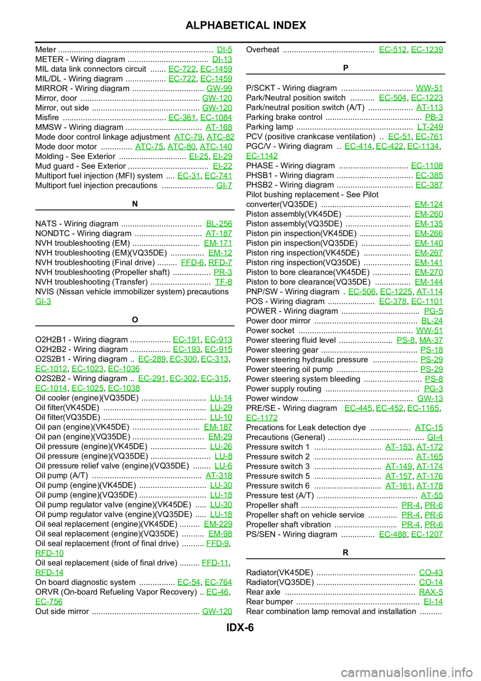
MIRROR - Wiring diagram ................................ GW-99
Mirror, door ..................................................... GW-120
Mirror, out side ................................................ GW-120
Misfire .............................................. EC-361, EC-1084
MMSW - Wiring diagram .................................. AT-168
Mode door control linkage adjustment ATC-79, ATC-82
Mode door motor .............. ATC-75, ATC-80, ATC-140
Molding - See Exterior .............................. EI-25, EI-29
Mud guard - See Exterior .................................... EI-22
Multiport fuel injection (MFI) system .... EC-31, EC-741
Multiport fuel injection precautions ....................... GI-7
N
NATS - Wiring diagram .................................... BL-256
NONDTC - Wiring diagram .............................. AT-187
NVH troubleshooting (EM) .............................. EM-171
NVH troubleshooting (EM)(VQ35DE) ............... EM-12
NVH troubleshooting (Final drive) ......... FFD-6, RFD-7
NVH troubleshooting (Propeller shaft) ................. PR-3
NVH troubleshooting (Transfer) ........................... TF-8
NVIS (Nissan vehicle immobilizer system) precautions
GI-3
O
O2H2B1 - Wiring diagram .................. EC-191
, EC-913
O2H2B2 - Wiring diagram .................. EC-193, EC-915
O2S2B1 - Wiring diagram .. EC-289, EC-300, EC-313,
EC-1012
, EC-1023, EC-1036
O2S2B2 - Wiring diagram .. EC-291, EC-302, EC-315,
EC-1014
, EC-1025, EC-1038
Oil cooler (engine)(VQ35DE) ............................. LU-14
Oil filter(VK45DE) .............................................. LU-29
Oil filter(VQ35DE) .............................................. LU-10
Oil pan (engine)(VK45DE) .............................. EM-187
Oil pan (engine)(VQ35DE) ................................ EM-29
Oil pressure (engine)(VK45DE) ......................... LU-26
Oil pressure (engine)(VQ35DE) ........................... LU-8
Oil pressure relief valve (engine)(VQ35DE) ........ LU-6
Oil pump (A/T) ................................................. AT-318
Oil pump (engine)(VK45DE) .............................. LU-30
Oil pump (engine)(VQ35DE) .............................. LU-18
Oil pump regulator valve (engine)(VK45DE) ..... LU-30
Oil pump regulator valve (engine)(VQ35DE) ..... LU-18
Oil seal replacement (engine)(VK45DE) ......... EM-229
Oil seal replacement (engine)(VQ35DE) .......... EM-98
Oil seal replacement (front of final drive) .......... FFD-9,
RFD-10
Oil seal replacement (side of final drive) ......... FFD-11,
RFD-14
On board diagnostic system ................ EC-54, EC-764
ORVR (On-board Refueling Vapor Recovery) .. EC-46,
EC-756
Out side mirror ................................................ GW-120
Overheat ......................................... EC-512, EC-1239
P
P/SCKT - Wiring diagram ................................ WW-51
Park/Neutral position switch ........... EC-504, EC-1223
Park/neutral position switch (A/T) .................... AT-113
Parking brake control ........................................... PB-3
Parking lamp .................................................... LT-249
PCV (positive crankcase ventilation) .. EC-51, EC-761
PGC/V - Wiring diagram .. EC-414, EC-422, EC-1134,
EC-1142
PHASE - Wiring diagram ............................... EC-1108
PHSB1 - Wiring diagram .................................. EC-385
PHSB2 - Wiring diagram .................................. EC-387
Pilot bushing replacement - See Pilot
converter(VQ35DE) ........................................ EM-124
Piston assembly(VK45DE) ............................. EM-260
Piston assembly(VQ35DE) ............................. EM-135
Piston pin inspection(VK45DE) ....................... EM-266
Piston pin inspection(VQ35DE) ...................... EM-140
Piston ring inspection(VK45DE) ..................... EM-267
Piston ring inspection(VQ35DE) ..................... EM-141
Piston to bore clearance(VK45DE) ................. EM-270
Piston to bore clearance(VQ35DE) ................ EM-144
PNP/SW - Wiring diagram . EC-506, EC-1225, AT-114
POS - Wiring diagram ..................... EC-378, EC-1101
POWER - Wiring diagram ................................... PG-5
Power door mirror .............................................. BL-24
Power socket ................................................... WW-51
Power steering fluid level ........................ PS-8, MA-37
Power steering gear ........................................... PS-18
Power steering hydraulic pressure .................... PS-29
Power steering oil pump .................................... PS-29
Power steering system bleeding .......................... PS-8
Power supply routing .......................................... PG-3
Power window .................................................. GW-13
PRE/SE - Wiring diagram EC-445, EC-452, EC-1165,
EC-1172
Precations for Leak detection dye .................. ATC-15
Precautions (General) ........................................... GI-4
Pressure switch 1 .............................. AT-153, AT-172
Pressure switch 2 ............................................ AT-165
Pressure switch 3 .............................. AT-149, AT-174
Pressure switch 5 .............................. AT-157, AT-176
Pressure switch 6 .............................. AT-161, AT-178
Pressure test (A/T) ............................................. AT-55
Propeller shaft ........................................... PR-4, PR-6
Propeller shaft on vehicle service ............. PR-4, PR-6
Propeller shaft vibration ............................ PR-4, PR-6
PS/SEN - Wiring diagram ............... EC-488, EC-1207
R
Radiator(VK45DE) ............................................ CO-43
Radiator(VQ35DE) ............................................ CO-14
Rear axle .......................................................... RAX-5
Rear bumper ....................................................... EI-14
Rear combination lamp removal and installation ..........
Page 3648 of 5621
IDX-7
A
C
D
E
F
G
H
I
J
K
L B
IDX
ALPHABETICAL INDEX
LT-266
Rear disc brake ................................................. BR-29
Rear door ............................................ BL-190, GW-67
Rear parcel shelf finisher ..................................... EI-42
Rear seat ......................................................... SE-172
Rear seat belt .................................................... SB-32
Rear suspension ............................................... RSU-5
Rear window ..................................................... GW-61
Rear window defogger ...................................... GW-73
Refrigerant connection precaution ..................... ATC-7
Refrigerant discharging evacuating charging ATC-151
Refrigerant general precaution .......................... ATC-7
Refrigerant lines ............................................ ATC-151
Refrigerant pressure sensor ........... EC-692, EC-1434,
ATC-98
, ATC-167
Refrigeration cycle ........................................... ATC-20
Removal and installation (A/T) ........... AT-271, AT-275
Removal and installation (Transfer) .................... TF-44
Reverse interlock door mirror ........................... GW-96
Revolution sensor (A/T) ...................... AT-119, AT-261
Rocker cover(VK45DE) ................................... EM-199
Rocker cover(VQ35DE) ..................................... EM-51
Room lamp - See Interior lamp ......................... LT-267
ROOM/L - Wiring diagram ................................ LT-274
RP/SEN - Wiring diagram ................ EC-693, EC-1435
S
SAE J1979 - Service $01 - 09 ............. EC-54
, EC-764
SEAT - Wiring diagram ...................................... SE-98
Seat belt inspection ........................................... SB-33
Seat belt, front ................................................... SB-30
Seat belt, rear .................................................... SB-32
Seat, rear ......................................................... SE-172
Self-diagnosis (Transfer) .................................... TF-22
SEN/PW - Wiring diagram ............... EC-500, EC-1219
SHIFT - Wiring diagram ................................... AT-230
Shift lock system .............................................. AT-229
Shock absorber (rear) ..................................... RSU-10
Side air bag (satellite) sensor .......................... SRS-46
Side curtain air bag .......................................... SRS-43
Side trim .............................................................. EI-37
SMJ (super multiple junction) .......................... PG-106
Spark plug replacement ..................................... MA-27
Spark plug replacement(VQ35DE) .................... MA-20
Spark plug(VK45DE) ....................................... EM-191
Spark plug(VQ35DE) ......................................... EM-43
Specification value ............................. EC-155, EC-868
Speedometer ........................................................ DI-5
Spiral cable ...................................................... SRS-40
SROOF - Wiring diagram .................................. RF-13
SRS - See Supplemental Restraint System ...... SRS-5
SRS - Wiring diagram ...................................... SRS-12
SRS Trouble diagnoses ..................................... SRS-8
Stabilizer bar (rear) ......................................... RSU-17
Stall test (A/T) .................................................... AT-53
Standardized relay ........................................... PG-109
START - Wiring diagram ................................... SC-11
Starter ................................................................ SC-10
Starting system .................................................. SC-10
Steering gear and linkage inspection ................ MA-36
Steering linkage ................................................. PS-18
Steering wheel and column ................... PS-10, PS-13
Steering wheel turning force .............................. PS-10
Stop lamp .......................................................... LT-243
Stop lamp switch .............................. EC-598, EC-1329
STSIG - Wiring diagram ................................... AT-109
Sun roof, electric ................................................ RF-10
Sunload sensor ............................. ATC-119, ATC-128
Sunroof .................................................. RF-25, RF-28
Sunshade ............................................................ EI-44
Supplemental Restraint System ....................... SRS-5
Supplemental restraint system - Wiring diagram ..........
SRS-12
Suspension ....................................................... MA-37
Symbols and abbreviations ...................... GI-11, GI-24
System readiness test (SRT) code ...... EC-60, EC-770
T
Tachometer ........................................................... DI-5
Tail lamp ........................................................... LT-249
TCM circuit diagram ........................................... AT-52
TCM inspection table ......................................... AT-89
Thermostat(VK45DE) ....................................... CO-55
Thermostat(VQ35DE) ....................................... CO-29
Three way catalyst function (Bank 1) EC-392, EC-1113
Three way catalyst function (Bank 2) EC-392, EC-1113
Three way catalyst precautions ............................ GI-6
Three way catalyst(VK45DE) .......................... EM-183
Throttle control motor ....................... EC-619, EC-1351
Throttle control motor relay .............. EC-607, EC-1338
Throttle position sensor (TPS) .......... EC-231, EC-354,
EC-533
, EC-535, EC-640, EC-954, EC-1077, EC-1259,
EC-1261
, EC-1372
Throttle valve closed position learning . EC-95, EC-806
Tie-rod ............................................................... PS-18
Timing chain(VK45DE) ................................... EM-203
Timing chain(VQ35DE) ..................................... EM-64
Tire rotation ....................................................... MA-35
TLID - Wiring diagram ...................................... BL-211
Top tether strap child restraint ........................... SB-37
Torque converter installation ............. AT-274, AT-277
Torque convertor clutch solenoid valve AT-126, AT-128
TPS1 - Wiring diagram .................... EC-356, EC-1079
TPS2 - Wiring diagram ...................... EC-233, EC-956
TPS3 - Wiring diagram .................... EC-642, EC-1374
Transfer control unit inspection table ................. TF-20
TRNSCV - Wiring diagram ............................... BL-281
Trouble diagnoses .............................................. GI-12
Trunk lid ........................................................... BL-203
Trunk lid opener - See Trunk lid ...................... BL-209
TURN - Wiring diagram .................................... LT-215
Turn signal lamp ............................................... LT-211
Two trip detection logic ........................ EC-54, EC-764
Tyre pressure monitoring system - trouble diagnoses ..
WT-13
Page 4431 of 5621

LT-4Revision: 2006 January2006 M35/M45 HAZARD SWITCH ..................................................231
Removal and Installation ......................................231
REMOVAL ........................................................
.231
COMBINATION SWITCH ........................................232
Wiring Diagram — COMBSW — ..........................232
Combination Switch Reading Function .................233
Terminals and Reference Values for BCM ............233
CONSULT-II Functions (BCM) ..............................238
CONSULT-II BASIC OPERATION .....................238
DATA MONITOR ................................................239
Combination Switch Inspection ............................240
Removal and Installation ......................................242
STOP LAMP ............................................................243
Wiring Diagram — STOP LAMP — ......................243
High-Mounted Stop Lamp .....................................245
BULB REPLACEMENT, REMOVAL AND
INSTALLATION ..................................................245
Stop Lamp ............................................................245
BULB REPLACEMENT .....................................245
BULB REPLACEMENT .....................................245
BACK-UP LAMP .....................................................246
Wiring Diagram — B/LAMP — .............................246
Bulb Replacement ...............................................
.247
Removal and Installation ......................................248
REMOVAL ........................................................
.248
INSTALLATION ..................................................248
PARKING, LICENSE PLATE AND TAIL LAMPS ....249
Component Parts and Harness Connector Location .249
System Description ...............................................249
OUTLINE ...........................................................249
OPERATION BY LIGHTING SWITCH ...............250
COMBINATION SWITCH READING FUNCTION .250
EXTERIOR LAMP BATTERY SAVER CONTROL .250
CAN Communication System Description ............250
CAN Communication Unit .....................................250
Schematic .............................................................251
Wiring Diagram — TAIL/L — ................................252
Terminals and Reference Values for BCM ............257
Terminals and Reference Values for IPDM E/R ....258
How to Perform Trouble Diagnoses ......................258
Preliminary Check ................................................258
CHECK POWER SUPPLY AND GROUND CIR-
CUIT ..................................................................258
CONSULT-II Functions (BCM) ..............................259
CONSULT-II Functions (IPDM E/R) ......................259
Parking, License Plate and Tail Lamps Do Not Illu-
minate ...................................................................260
Parking, License Plate and Tail Lamps Do Not Turn
OFF (After Approx. 10 Minutes) ...........................264
License Plate Lamp ..............................................265
BULB REPLACEMENT .....................................265
Removal and Installation ......................................265
REMOVAL ........................................................
.265
INSTALLATION ..................................................265
Front Parking (Clearance) Lamp ..........................265
BULB REPLACEMENT .....................................265
REMOVAL AND INSTALLATION .......................265
REAR COMBINATION LAMP .................................266
Bulb Replacement ...............................................
.266REAR TURN SIGNAL LAMP BULB, STOP/TAIL
LAMP BULB ...................................................... .266
Removal and Installation .......................................266
REMOVAL ..........................................................266
INSTALLATION ..................................................266
INTERIOR ROOM LAMP ........................................267
Component Parts and Harness Connector Location .267
System Description ...............................................267
ROOM LAMP TIMER BASIC OPERATION .......267
POWER SUPPLY AND GROUND .....................268
SWITCH OPERATION .......................................269
ROOM LAMP TIMER OPERATION ...................270
CONDITIONS FOR CANCELING TIMER ..........271
ROOM LAMP TIMER INAPPLICABLE LAMPS
OPERATION ......................................................271
INTERIOR ROOM LAMP BATTERY SAVER
FUNCTION .......................................................
.271
Schematic .............................................................272
Wiring Diagram — ROOM/L — .............................274
Terminals and Reference Values for BCM ............281
How to Perform Trouble Diagnoses ......................282
Preliminary Check .................................................283
CHECK POWER SUPPLY AND GROUND CIR-
CUIT ...................................................................283
CONSULT-II Functions (BCM) ..............................284
CONSULT-II BASIC OPERATION .....................284
WORK SUPPORT (INT LAMP) .........................285
DATA MONITOR (INT LAMP) ............................286
ACTIVE TEST (INT LAMP) ................................287
WORK SUPPORT (BATTERY SAVER) .............287
DATA MONITOR (BATTERY SAVER) ...............287
ACTIVE TEST (BATTERY SAVER) ...................288
Interior Room Lamp Control Does Not Operate ....289
Map Lamp .............................................................291
BULB REPLACEMENT ......................................291
REMOVAL AND INSTALLATION .......................291
Personal Lamp ......................................................291
BULB REPLACEMENT ......................................291
REMOVAL AND INSTALLATION .......................291
Foot Lamp (Driver Side) .......................................
.292
BULB REPLACEMENT ......................................292
REMOVAL AND INSTALLATION .......................292
Foot Lamp (Passenger Side) ................................293
BULB REPLACEMENT ......................................293
REMOVAL AND INSTALLATION .......................293
Vanity Mirror Lamp ................................................293
BULB REPLACEMENT ......................................293
Step Lamp .............................................................294
BULB REPLACEMENT ......................................294
REMOVAL AND INSTALLATION .......................294
Kicking Plate Illumination .....................................
.294
BULB REPLACEMENT ......................................294
REMOVAL AND INSTALLATION .......................294
Trunk Room Lamp (Upper/Lower) ........................294
BULB REPLACEMENT ......................................294
REMOVAL AND INSTALLATION .......................294
ILLUMINATION ........................................................295
System Description ...............................................295
OUTLINE ...........................................................295
Page 4696 of 5621
INTERIOR ROOM LAMP
LT-269
C
D
E
F
G
H
I
J
L
MA
B
LT
Revision: 2006 January2006 M35/M45
through front door lock assembly (driver side) (key cylinder switch) terminals 5 and 4
through grounds M16 and M70.
When a signal, or combination of door open signals is received by BCM, ground is supplied
to foot lamp driver side and passenger side terminals 2
to personal lamp LH and RH terminals 1
to map lamp terminal 2 and 5
through BCM terminal 48,
to step lamp (driver side, passenger side, rear LH and RH) terminals 2
to kicking plate illumination (driver side and passenger side) terminals 2
through BCM terminal 47.
With power and ground supplied, the interior lamps illuminate.
SWITCH OPERATION
When any front door switch is ON (door is opened), ground is supplied
to step lamp (driver side, passenger side, rear LH and RH) terminals 2
to kicking plate illumination (driver side and passenger side) terminals 2
through BCM terminal 47.
And power is supplied
through BCM terminal 41
to step lamp (driver side, passenger side, rear LH and RH) terminals 1
to kicking plate illumination (driver side and passenger side) terminals 1.
When any door switch is ON (door is opened) and personal lamp and map lamp is DOOR position, ground is
supplied
to personal lamp LH and RH terminal 1
to map lamp terminals 2 and 5
through BCM terminal 48.
And power is supplied
through BCM terminal 41
to personal lamp LH and RH terminals 3
to map lamp terminal 3.
When map lamp switch is ON, ground is supplied
to map lamp terminal 1
through grounds M16 and M70.
And power is supplied
through BCM terminal 41
to map lamp terminal 3.
When personal lamp LH and RH switch is ON, ground is supplied
to personal lamp LH and RH terminals 2
through grounds M16 and M70.
And power is supplied
through BCM terminal 41
to personal lamp LH and RH terminals 3.
When trunk lid lock assembly (trunk room lamp switch) is ON, ground is supplied
to trunk room lamp (upper and lower) terminals 2
through trunk lid lock assembly (trunk room lamp switch) terminals 1 and 2
through grounds B5, B40 and B131.
And power is supplied
through BCM terminal 41
to trunk room lamp (upper and lower) terminals 1.
When vanity mirror lamp LH and RH switch is ON, ground is supplied
Page 4697 of 5621
LT-270
INTERIOR ROOM LAMP
Revision: 2006 January2006 M35/M45
to vanity mirror lamp LH and RH terminals 2
through grounds M16 and M70.
And power is supplied
through BCM terminal 41
to vanity mirror lamp (LH and RH) terminals 1.
ROOM LAMP TIMER OPERATION
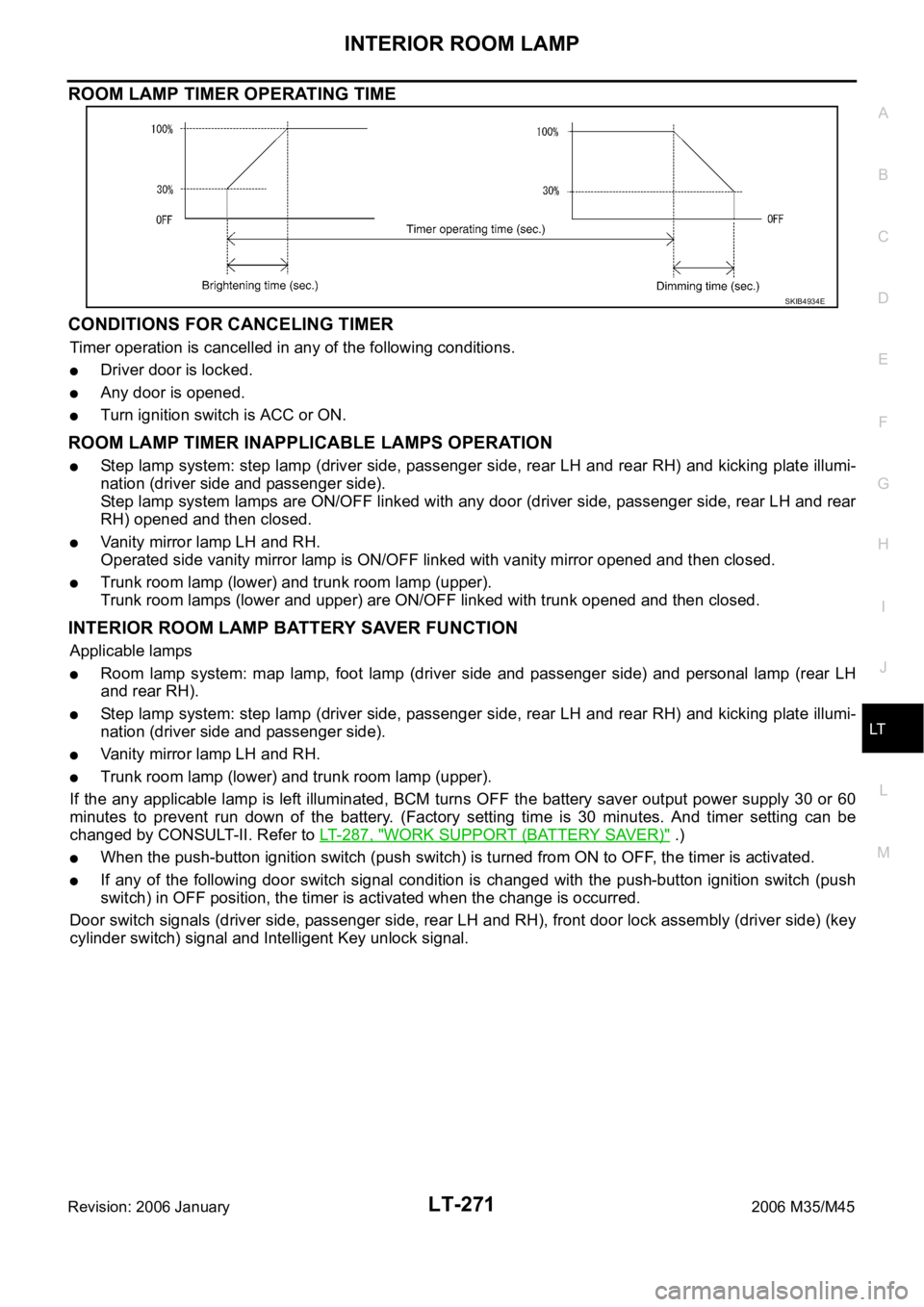
BCM controls applicable lamps to illuminate for 15 seconds (can be set maximum 30 seconds) by timer oper-
ation under following conditions. BCM also controls applicable lamps to brighten for 1 second (can be set max-
imum 5 seconds) when turned ON, or to dim for 3 seconds (can be set maximum 5 seconds) when turned
OFF. (Timer operating time and dimming/brightening time can be changed with CONSULT-II. Refer to LT- 2 8 5 ,
"WORK SUPPORT (INT LAMP)" .) This control operates as follows.
Applicable lamps
Room lamp system: map lamp, foot lamp (driver side and passenger side) and personal lamp (rear LH
and rear RH).
BCM controls room lamp timer operation under following condition.
Condition 1: Door lock state changes.*
BCM judges as the door lock is unlocked under either case below.
–The Intelligent Key unit sends door lock/unlock trunk open request signal (driver side unlock or passenger
side unlock) to BCM through CAN communication line by unlock operation of intelligent key, outside key
antenna and front door request switch (driver side) or outside key antenna and front door request switch
(passenger side).
–Key cylinder switch state (unlock) signal is sent to BCM through power window serial link when front door
lock assembly (driver side) (key cylinder switch) is unlocked (ON) by power window main switch unlock
operation.
And fulfills all the conditions below.
–The engine switch (push switch) is OFF.
–All the doors are closed.
*: This setting can be changed by CONSULT-II. Refer to LT-285, "
WORK SUPPORT (INT LAMP)" .
Condition 2: Any door switch state changes.*
The BCM terminal value of operated door switch is changed when any door is opened and then closed.
From that BCM judges as the door is opened and then closed.
And fulfills all the conditions below.
–The engine switch (push switch) is OFF.
–All the doors are closed.
*: This setting can be changed by CONSULT-II. Refer to LT-285, "
WORK SUPPORT (INT LAMP)" .
Condition 3: Engine switch (push switch) state changes.*
The Intelligent Key unit judges as the engine switch (push switch) is OFF and sends push-button ignition
switch (push switch) signal to PDU (power distribution unit) when push-button ignition switch (push
switch) turned OFF. Then PDU (power distribution unit) turns OFF, IGN power supply and ACC power
supply.
And fulfills the conditions below.
–All the doors are closed.
*:This setting can be changed by CONSULT-II. Refer to LT- 2 8 5 , "
WORK SUPPORT (INT LAMP)" .
NOTE:
When timer operation signal is input during former timer operation, BCM goes for latter timer operation.
Page 4698 of 5621
INTERIOR ROOM LAMP
LT-271
C
D
E
F
G
H
I
J
L
MA
B
LT
Revision: 2006 January2006 M35/M45
ROOM LAMP TIMER OPERATING TIME
CONDITIONS FOR CANCELING TIMER
Timer operation is cancelled in any of the following conditions.
Driver door is locked.
Any door is opened.
Turn ignition switch is ACC or ON.
ROOM LAMP TIMER INAPPLICABLE LAMPS OPERATION
Step lamp system: step lamp (driver side, passenger side, rear LH and rear RH) and kicking plate illumi-
nation (driver side and passenger side).
Step lamp system lamps are ON/OFF linked with any door (driver side, passenger side, rear LH and rear
RH) opened and then closed.
Vanity mirror lamp LH and RH.
Operated side vanity mirror lamp is ON/OFF linked with vanity mirror opened and then closed.
Trunk room lamp (lower) and trunk room lamp (upper).
Trunk room lamps (lower and upper) are ON/OFF linked with trunk opened and then closed.
INTERIOR ROOM LAMP BATTERY SAVER FUNCTION
Applicable lamps
Room lamp system: map lamp, foot lamp (driver side and passenger side) and personal lamp (rear LH
and rear RH).
Step lamp system: step lamp (driver side, passenger side, rear LH and rear RH) and kicking plate illumi-
nation (driver side and passenger side).
Vanity mirror lamp LH and RH.
Trunk room lamp (lower) and trunk room lamp (upper).
If the any applicable lamp is left illuminated, BCM turns OFF the battery saver output power supply 30 or 60
minutes to prevent run down of the battery. (Factory setting time is 30 minutes. And timer setting can be
changed by CONSULT-II. Refer to LT-287, "
WORK SUPPORT (BATTERY SAVER)" .)
When the push-button ignition switch (push switch) is turned from ON to OFF, the timer is activated.
If any of the following door switch signal condition is changed with the push-button ignition switch (push
switch) in OFF position, the timer is activated when the change is occurred.
Door switch signals (driver side, passenger side, rear LH and RH), front door lock assembly (driver side) (key
cylinder switch) signal and Intelligent Key unlock signal.
SKIB4934E
Page 4720 of 5621
INTERIOR ROOM LAMP
LT-293
C
D
E
F
G
H
I
J
L
MA
B
LT
Revision: 2006 January2006 M35/M45
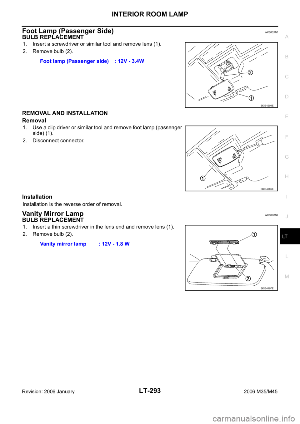
Foot Lamp (Passenger Side)NKS003TC
BULB REPLACEMENT
1. Insert a screwdriver or similar tool and remove lens (1).
2. Remove bulb (2).
REMOVAL AND INSTALLATION
Removal
1. Use a clip driver or similar tool and remove foot lamp (passenger
side) (1).
2. Disconnect connector.
Installation
Installation is the reverse order of removal.
Vanity Mirror LampNKS003TD
BULB REPLACEMENT
1. Insert a thin screwdriver in the lens end and remove lens (1).
2. Remove bulb (2).Foot lamp (Passenger side) : 12V - 3.4W
SKIB4204E
SKIB4205E
Vanity mirror lamp : 12V - 1.8 W
SKIB4197E