2006 INFINITI M35 mirror
[x] Cancel search: mirrorPage 4723 of 5621

LT-296
ILLUMINATION
Revision: 2006 January2006 M35/M45
ILLUMINATION OPERATION BY LIGHTING SWITCH
With the lighting switch in the 1ST or 2ND position (or if the auto light system is activated), the BCM receives
input signal requesting the illumination lamps to illuminate. This input signal is communicated to the IPDM E/R
across the CAN communication lines. The CPU located in the IPDM E/R controls the tail lamp relay coil,
which, when energized, directs power
through IPDM E/R terminal 21
to combination meter terminal 13
to LDW switch (illumination) terminal 5 (with lane departure warning)
to VDC off switch (illumination) terminal 3
to trunk lid opener switch (illumination) terminal 3
to combination switch (spiral cable) terminal 24
to door mirror remote control switch (illumination) terminal 16
to AFS switch (illumination) terminal 5 (with AFS)
to rear sunshade front switch (illumination) terminal 5 (with rear control switch)
to A/T illumination terminal 1
to snow mode switch (illumination) terminal 5 (AWD models)
to rear control cancel switch (illumination) terminal 4 (with rear control switch)
to clock terminal 3
to multifunction switch terminal 3
to audio unit terminal 9
to DVD player terminal 18 (with DVD player)
to NAVI control unit terminal 61 (with navigation system)
to AV control unit terminal 61 (without navigation system)
to climate controlled seat switch driver side (illumination) terminal 7 (with climate controlled seat)
to climate controlled seat switch passenger side (illumination) terminal 7 (with climate controlled seat)
to ashtray illumination (rear LH) terminal 1
to ashtray illumination (rear RH) terminal 1
to illumination control switch terminal 1
to cigarette lighter socket (illumination) terminal 2
to map lamp (illumination) terminal 8
to power window main switch illumination terminal 1
to glove box lamp terminal 1
to rear control switch terminal 2
to rear power seat switch RH (illumination) terminal 4 (with rear control switch)
to rear heated seat switch RH (illumination) terminal 7 (with rear control switch)
to rear sunshade cancel relay terminal 6 (with rear control switch)
to automatic return cancel switch (illumination) terminal 4 (with rear control switch)
to rear power seat switch LH (illumination) terminal 4 (with rear control switch) and
to rear heated seat switch LH (illumination) terminal 7 (with rear control switch),
through Intelligent Key unit terminal 12
to push button ignition switch (illumination) terminal 3.
Ground is supplied
to combination meter terminal 14
to combination meter terminal 9, 10 and 11
to push button ignition switch (illumination) terminal 2
to LDW switch (illumination) terminal 4 (with lane departure warning)
to VDC off switch (illumination) terminal 4
to trunk lid opener switch (illumination) terminal 4
to combination switch (spiral cable) terminal 25
Page 4724 of 5621

ILLUMINATION
LT-297
C
D
E
F
G
H
I
J
L
MA
B
LT
Revision: 2006 January2006 M35/M45
to door mirror remote control switch (illumination) terminal 15
to AFS switch (illumination) terminal 6 (with AFS)
to rear sunshade front switch (illumination) terminal 6 (with rear control switch)
to A/T illumination terminal 2
to snow mode switch (illumination) terminal 6 (ADW models)
to rear control cancel switch (illumination) terminal 5 (with rear control switch)
to clock terminal 4
to multifunction switch terminal 4
to audio unit terminal 8
to DVD player terminal 17 (With DVD player)
to climate controlled seat switch driver side (illumination) terminal 8 (with climate controlled seat) and
to climate controlled seat switch passenger side (illumination) terminal 8 (with climate controlled seat)
through illumination control switch terminal 2
to illumination control switch terminal 3
through grounds M16 and M70,
to cigarette lighter socket (illumination) terminal 1
to map lamp (illumination) terminal 4
to power window main switch illumination terminal 2 and
to glove box lamp terminal 2
through grounds M16 and M70,
to ashtray illumination (rear LH) terminal 2
to ashtray illumination (rear RH) terminal 2
to automatic return cancel switch (illumination) terminal 2 (With rear control switch)
to rear power seat switch LH (illumination) terminal 3 (With rear control switch)
to rear heated seat switch LH (illumination) terminal 8 (With rear control switch)
through grounds B5, B40 and B131,
through rear sunshade cancel relay terminal 7(With rear control switch)
to rear sunshade rear switch (illumination) terminal 7 (With rear control switch)
through grounds B5, B40, B131 and B559.
to rear control switch terminal 4
to rear power seat switch RH (illumination) terminal 3 (With rear control switch)
to rear heated seat switch RH (illumination) terminal 8 (With rear control switch)
through grounds B5, B40, B131 and B559.
With power and ground supplied, illumination lamps illuminate.
EXTERIOR LAMP BATTERY SAVER CONTROL
BCM activates the exterior lamp battery saver control function and turns off the exterior lamps to prevent bat-
tery from over discharge when the combination switch (lighting switch) is in 1ST or 2ND position and/or the
front fog lamp switch ON and the door lock operation is performed by keyless entry system.
CAN Communication System DescriptionNKS003TI
CAN (Controller Area Network) is a serial communication line for real time application. It is an on-vehicle mul-
tiplex communication line with high data communication speed and excellent error detection ability. Many elec-
tronic control units are equipped onto a vehicle, and each control unit shares information and links with other
control units during operation (not independent). In CAN communication, control units are connected with 2
communication lines (CAN H line, CAN L line) allowing a high rate of information transmission with less wiring.
Each control unit transmits/receives data but selectively reads required data only.
CAN Communication UnitNKS003TJ
Refer to LAN-34, "CAN Communication Unit" .
Page 4742 of 5621

BULB SPECIFICATIONS
LT-315
C
D
E
F
G
H
I
J
L
MA
B
LT
Revision: 2006 January2006 M35/M45
BULB SPECIFICATIONSPFP:26297
HeadlampNKS003TQ
Exterior LampNKS003TR
Interior Lamp/IlluminationNKS003TS
NOTE:
This lamp is used as both front ashtray and front cigarette lighter. Item Wattage (W)
Low (Halogen type)55 (H1)
Low (Xenon type)35 (D2S)
High60 (HB3)
Item Wattage (W)
Front combination lampFront turn signal lamp 21
Parking lamp (Clearance lamp) 5
Front side marker lamp 5
Rear combination lampStop/Tail lamp LED
Rear turn signal lamp 21 (amber)
Rear side marker lamp LED
Back-up lamp18
Side turn signal lamp5
Front fog lamp55 (H11)
License plate lamp5
High-mounted stop lampLED
Item Wattage (W)
Map lamp8
Personal lamp8
Trunk room lampUpper
5
Lower
Front ashtray and front cigarette lighter illumination
NOTE1.4
Rear ashtray illumination1.4
Ste p lamp5
Vanity mirror lamp1.8
Center console indirect illuminationLED
Glove box lamp1.4
Foot lampDriver side
3.4
Passenger side
Kicking plateDriver side
LED
Passenger side
Power window indirect illuminationLED
Page 4921 of 5621

PG-94
HARNESS
Revision: 2006 January2006 M35/M45
ETC3 EC Electric Throttle Control Motor
F/FOG LT Front Fog Lamp
F/PUMP EC Fuel Pump
FPCM EC Fuel Pump Control Module
FTS AT A/T Fluid Temperature Sensor Circuit
FTTS EC Fuel Tank Temperature Sensor
FUELB1 EC Fuel Injection System Function (Bank 1)
FUELB2 EC Fuel Injection System Function (Bank 2)
H/LAMP LT Headlamp
HORN WW Horn
HSEAT SE Heated Seat
I/KEY BL Intelligent Key System
I/MIRR GW Inside Mirror (Auto Anti-Dazzling Mirror)
IATS EC Intake Air Temperature Sensor
ICC ACS Intelligent Cruise Control System
ICC/BS EC ICC Brake Switch
ICC/SW EC ICC Steering Switch
ICCBOF EC ICC Brake Switch
IGNSYS EC Ignition System
ILL LT Illumination
INJECT EC Injector
IVCB1 EC Intake Valve Timing Control Solenoid Valve Bank 1
IVCB2 EC Intake Valve Timing Control Solenoid Valve Bank 2
IVCSB1 EC Intake Valve Timing Control Position Sensor Bank 1
IVCSB2 EC Intake Valve Timing Control Position Sensor Bank 2
IVTB1 EC Intake Valve Timing Control System (Bank 1)
IVTB2 EC Intake Valve Timing Control System (Bank 2)
KS EC Knock Sensor
LDW DI Lane Departure Warning System
MAFS EC Mass Air Flow Sensor
MAIN AT Main Power Supply and Ground Circuit
MAIN EC Main Power Supply and Ground Circuit
METER DI Speedometer, Tachometer, Temp., Oil and Fuel Gauges
MIL/DL EC MIL & Data Link Connector
MIRROR GW Door Mirror
MMSW AT Manual Mode Switch
NATS BL Nissan Anti-Theft System
NONDTC AT Non-Detective Items
O2H2B1 EC Heated Oxygen Sensor 2 Heater Bank 1
O2H2B2 EC Heated Oxygen Sensor 2 Heater Bank 2
O2S2B1 EC Heated Oxygen Sensor 2 Bank 1
O2S2B2 EC Heated Oxygen Sensor 2 Bank 2
P/SCKT WW Power Socket
PDU PG Power Distribution Unit Code Section Wiring Diagram Name
Page 5182 of 5621

SE-1
SEAT
I BODY
CONTENTS
C
D
E
F
G
H
J
K
L
M
SECTION SE
A
B
SE
Revision: 2006 January2006 M35/M45
SEAT
PRECAUTIONS .......................................................... 3
Precautions for Supplemental Restraint System
(SRS) “AIR BAG” and “SEAT BELT PRE-TEN-
SIONER” .................................................................. 3
Service Notice .......................................................... 3
Precautions for Work ...........................................
..... 3
PREPARATION ........................................................... 4
Special Service Tools ............................................... 4
Commercial Service Tools ........................................ 4
SQUEAK AND RATTLE TROUBLE DIAGNOSES ..... 5
Work Flow ................................................................ 5
CUSTOMER INTERVIEW ..................................... 5
DUPLICATE THE NOISE AND TEST DRIVE ....... 6
CHECK RELATED SERVICE BULLETINS ........... 6
LOCATE THE NOISE AND IDENTIFY THE
ROOT CAUSE ...................................................... 6
REPAIR THE CAUSE ........................................... 6
CONFIRM THE REPAIR ....................................... 7
Generic Squeak and Rattle Troubleshooting ........... 7
INSTRUMENT PANEL .......................................... 7
CENTER CONSOLE ............................................. 7
DOORS ................................................................. 7
TRUNK .................................................................. 8
SUNROOF/HEADLINING ..................................... 8
SEATS ................................................................... 8
UNDERHOOD ....................................................... 8
Diagnostic Worksheet .............................................. 9
AUTOMATIC DRIVE POSITIONER ...........................11
Component Parts And Harness Connector Location
.... 11
System Description ................................................ 12
MANUAL OPERATION ....................................... 12
MEMORY OPERATION ...................................... 12
EXITING OPERATION ........................................ 14
ENTRY OPERATION .......................................... 14
INTELLIGENT KEY INTERLOCK OPERATION ... 15
FAIL-SAFE MODE .............................................. 15
INITIALIZATION PROCEDURE .......................... 16
SETTING CHANGE FUNCTION ......................... 16
CAN Communication System Description .............. 16CAN Communication Unit ....................................... 16
Schematic ............................................................... 17
Wiring Diagram—AUT/DP— .................................. 19
Terminals and Reference Values for BCM .............. 30
Terminals and Reference Value for Intelligent Key
Unit ......................................................................... 30
Terminals and Reference Values for Driver Seat
Control Unit ............................................................. 31
Terminals and Reference Values for Automatic
Drive Positioner Control Unit .................................. 33
CONSULT-II Function (AUTO DRIVE POS.) .......... 35
CONSULT-II INSPECTION PROCEDURE .......... 35
SELF-DIAGNOSIS RESULTS ............................. 36
DATA MONITOR ................................................. 37
ACTIVE TEST ..................................................... 38
WORK SUPPORT ............................................... 38
Work Flow ............................................................... 39
Symptom Chart ....................................................... 39
CAN Communication Inspection Using CONSULT-
II (Self-Diagnosis) ................................................... 41
BCM Power Supply and Ground Circuit Check ...... 41
Driver Seat Control Unit Power Supply and Ground
Circuit Check .......................................................... 42
Automatic Drive Positioner Power Supply and
Ground Circuit Check ............................................. 43
Sliding Motor Circuit Check .................................... 44
Reclining Motor LH Circuit Check ........................... 45
Front Lifting Motor Circuit Check ............................ 46
Rear Lifting Motor Circuit Check ............................. 48
Telescopic Motor Circuit Check .............................. 49
Tilt Motor Circuit Check .......................................
... 50
Sliding Sensor Circuit Check .................................. 52
Reclining Sensor Circuit Check .............................. 54
Front Lifting Sensor Circuit Check .......................... 56
Rear Lifting Sensor Circuit Check .......................... 58
Telescopic Sensor Circuit Check ............................ 60
Tilt Sensor Circuit Check ........................................ 62
Door Mirror Sensor LH Circuit Check ..................... 63
Door Mirror Sensor RH Circuit Check .................... 66
Sliding Switch Circuit Check ................................... 68
Page 5183 of 5621

SE-2Revision: 2006 January2006 M35/M45 Reclining Switch Circuit Check ............................... 70
Lifting Switch (Front) Circuit Check ........................ 72
Lifting Switch (Rear) Circuit Check ......................... 74
Power Seat Switch Ground Circuit Check .............. 75
Telescopic Switch Circuit Check ............................. 76
Tilt Switch Circuit Check ......................................
... 78
Seat Memory and Set Switch Circuit Check ........... 80
Seat Memory Indicator Lamp Circuit Check ........... 81
Door Mirror Sensor Power Supply and Ground Cir-
cuit Check ............................................................... 83
A/T Device (Detention Switch) Circuit Check ......... 85
Front Door Switch (Driver Side) Circuit Check ....... 86
UART Communication Line Circuit Check .............. 87
Lumber Support Circuit Check ............................... 89
POWER SEAT(PASSENGER SIDE) ......................... 91
Component Parts and Harness Connector Location ... 91
Wiring Diagram—SEAT—/Passenger Side ............ 92
Terminals and Reference Values for BCM .............. 94
POWER SEAT(REAR) .............................................. 95
Component Parts and Harness Connector Location ... 95
System Description ................................................. 95
REAR POWER SEAT LH AND RH OPERATION ... 95
REAR SEAT RETREAT FUNCTION ................... 96
Schematic ............................................................... 97
Wiring Diagram—R/SEAT— ................................... 98
Terminals and Reference Values for Rear Seat Con-
trol Unit .................................................................102
Work Flow .............................................................103
Trouble Diagnoses Symptom Chart ......................103
Rear Power Seat Power Supply Circuit Inspection .103
Rear Seat Control Unit Power Supply and Ground
Circuit Inspection ..................................................104
Rear Seat Sliding Motor Circuit Inspection ...........105
Rear Power Seat Switch Circuit Inspection ..........106
Automatic Return Cancel Switch Circuit Inspection .108
Automatic Return Cancel Switch Inspection .........109
Rear Door Switch Circuit Inspection .....................110
Rear Seat Sliding Sensor Circuit Inspection ..........111
CLIMATE CONTROLLED SEAT .............................113
Component Parts and Harness Connector Location .113
System Description ...............................................113
Schematic .............................................................117
Wiring Diagram—C/SEAT— .................................118
Terminal and Reference Value for Climate Con-
trolled Seat Control Unit ......................................
.123
Work Flow .............................................................124
Preliminary Check ................................................124
Trouble Diagnoses Symptom Chart .....................
.125
Climate Controlled Seat Control Unit Power Supply
Circuit Check ........................................................126
Climate Controlled Seat Control Unit Power Supply
and Ground Circuit Inspection ..............................127
Climate Controlled Seat Switch Power Supply Cir-cuit Inspection .......................................................130
Climate Controlled Seat Switch Circuit Inspection .131
Climate Controlled Seat Switch Indicator Circuit
Inspection ..............................................................133
Seat Cushion Thermal Electric Device Circuit
Inspection ..............................................................135
Seatback Thermal Electric Device Circuit Inspec-
tion ........................................................................136
Seat Cushion Thermal Electric Device Sensor Cir-
cuit Inspection .......................................................137
Seatback Thermal Electric Device Sensor Circuit
Inspection ..............................................................139
Climate Controlled Seat Blower Motor Circuit
Inspection ..............................................................140
Climate Controlled Seat Control Unit Inspection ...142
HEATED SEAT ........................................................143
Component Parts and Harness Connector Location .143
System Description ...............................................143
Schematic .............................................................145
Wiring Diagram —HSEAT— .................................146
Terminals and Reference Values for Rear Seat Con-
trol Unit ..................................................................151
Work Flow .............................................................151
Trouble Diagnoses Symptom Chart ......................151
Rear Heated Seat Power Supply and Ground Circuit
Inspection ..............................................................152
Rear Seat Control Unit Power Supply and Ground
Circuit Inspection ..................................................153
Rear Heated Seat Switch Circuit Inspection .........155
Rear Heated Seat Indicator Power Supply Circuit
Inspection ..............................................................157
Rear Heated Seat Indicator Circuit Inspection ......158
Rear Heated Seat Circuit Inspection .....................160
Rear Seatback Heater Circuit Inspection ..............161
FRONT SEAT ..........................................................163
Driver's Seat Components ....................................163
Passenger's Seat Components .............................165
Removal and Installation .......................................167
REMOVAL ..........................................................167
INSTALLATION ..................................................167
Disassembly and Assembly ..................................168
SEATBACK ........................................................168
SEAT CUSHION ................................................169
CLIMATE CONTROLLED SEAT ........................171
REAR SEAT .............................................................172
Bench Seat Components ......................................172
Power Seat (Split Type) Components ...................174Removal and Installation .......................................176
BENCH SEAT ....................................................176
POWER SEAT ...................................................176
Disassembly and Assembly ..................................177
BENCH SEAT ....................................................177
POWER SEAT ...................................................179
Page 5192 of 5621

AUTOMATIC DRIVE POSITIONER
SE-11
C
D
E
F
G
H
J
K
L
MA
B
SE
Revision: 2006 January2006 M35/M45
AUTOMATIC DRIVE POSITIONERPFP:28491
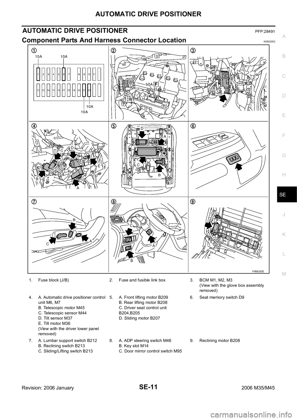
Component Parts And Harness Connector LocationNIS0025Q
PIIB6292E
1. Fuse block (J/B) 2. Fuse and fusible link box 3. BCM M1, M2, M3
(View with the glove box assembly
removed)
4. A. Automatic drive positioner control
unit M6, M7
B. Telescopic motor M45
C. Telescopic sensor M44
D. Tilt sensor M37
E. Tilt motor M36
(View with the driver lower panel
removed)5. A. Front lifting motor B209
B. Rear lifting motor B208
C. Driver seat control unit
B204,B205
D. Sliding motor B2076. Seat memory switch D9
7. A. Lumbar support switch B212
B. Reclining switch B213
C. Sliding/Lifting switch B2138. A. ADP steering switch M46
B. Key slot M14
C. Door mirror control switch M959. Reclining motor B208
Page 5193 of 5621

SE-12
AUTOMATIC DRIVE POSITIONER
Revision: 2006 January2006 M35/M45
System DescriptionNIS0025R
The system automatically moves the driver seat, steering and door mirror position by the driver seat con-
trol unit and the automatic drive positioner control unit. The driver seat control unit corresponds with the
automatic drive positioner control unit via UART communication. The driver seat control unit can store the
optimum driving positions (driver seat, steering and door mirror position) for 2 people. If the driver
changes, one-touch operation allows changing to the other driving position.
The driver seat, steering and door mirror position are adjusted automatically to the proper positions for the
driver in different ways: MEMORY OPERATION, EXITING OPERATION, ENTRY OPERATION and
INTELLIGENT KEY INTERLOCK OPERATION.
MANUAL OPERATION
The driving position (seat, steering and door mirror position) can be adjusted with the power seat switch, ADP
steering switch and door mirror control switch.
NOTE:
The door mirrors can be manually operated with the ignition switch in either ACC or ON.
MEMORY OPERATION
The driver seat control unit can store the optimum driving positions (seat, steering and door mirror position) for
2 people. If the front seat position is changed, one-touch (pressing desired memory switch for more than 0.5
second) operation allows changing to the other driving position.
Operation procedure
1. Turn ignition switch ON.
2. Press desired memory switch for 0.5 second. (Indicator LED illuminates.)
3. Driver seat, steering and door mirror will move to the memorized position.
(Indicator LED blinks during adjustment, then illuminates for 5 seconds.)
Operation Condition
If the following conditions are not satisfied, memory switch operation is not performed.
Ignition switch is in ON position.
Driver side power seat switch, ADP steering switch and door mirror control switch are not operated.
Seat memory switch and set switch are not operated.
Output malfunction is not detected.
CAN and UART communications are normal.
A/T selector lever position is in P position.
Detention switch malfunction is not detected.
[Detention switch malfunction is sensed when detention switch remains OFF, vehicle speed is higher than
7 km/H. (4 MPH).]
Input voltage from tilt sensor and telescopic sensor are normal.
NOTE:
The memory operation operates following order.
Function Description
Manual operationThe driving position (seat, steering and door mirror position) can be adjusted with
the power seat switch ADP steering switch or door mirror control switch.
Auto-
matic
operationMemory operation The seat, steering and door mirror move to the stored driving position by pushing
seat memory switch (1 or 2).
Entry/
Exiting
functionExiting operation At exit, the seat moves backward and the steering wheel moves upward.
Entry operationAt entry, the seat and steering wheel returns from exiting position to the previous
driving position before the exiting operation.
Intelligent Key interlock operationPerform memory operation, exiting operation and entry operation by pressing Intel-
ligent Key unlock button.